AMERICAN CHOPPER.
TITLE: DESIGN, ASSEMBLY AND RENDERING OF AMERICAN CHOPPER.
OBJECTIVES:
- To ideate, design, assemble and render the American chopper bike.
- To learn the SOLIDWORKS software as a design tool in industrial manner.
- To be industry ready for the role of Mechanical Design Engineer.
INTRODUCTION:
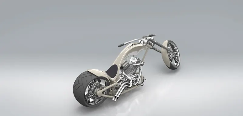
In this project I had built an American chopper. The designing started with ideation process followed by part modelling one by one for each part. After that parts are assembled in assembly environment and then rendered using SOLIDWORKS visualize.
DESIGN METHODOLOGY:
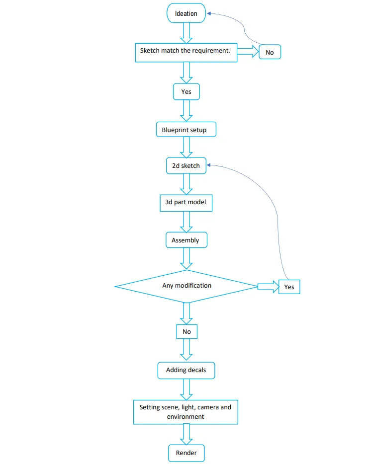
While designing anything in the industry it has to be pass from certain steps. It first started with ideation. In ideation the designer tries to portray the sketch on paper which is already created in his mind by doing some brainstorming. After several trial and error one sketch is finalised. After that 3d modelling of various part started. Once the modelling of all parts done they are assembled in assembly environment and then rendered using various rendering tools like photo view 360, SOLIDWORKS visualise.
Following flow chart represent the whole process of designing American chopper from beginning to end.
DESCRIPTION:
IDEATION:
Ideation process started with creating the mood board. Mood board is nothing but key things or experience that we want from the final product. After finishing mood board sketches are in photoshop, we can use pen and paper as well. After several trial and error final sketch Is obtained, which is then taken as base/blueprint for modelling various parts.
DESIGN AND 3D MODELLING:
Once ideation is completed the blueprints were imported to the SOLIDWORKS part modelling environment and modelling of various part as per blueprint was completed one by one.
Some of the most widely used feature in this project and the most important are described below.
- Extrude: This is main feature for converting 2d sketch into 3d model. While extrusion material is added to sketch.
- Extruded cut: Extruded cut is a similar feature to extrude but instead of adding material it removes material from body
- Revolve: Revolve feather used for creating circular bodies about central axis
- Revolved cut: Revolved cut feature is similar to the revolve feature but instead of adding material it removes material from the body in circular way.
- Linear pattern: Linear pattern is used when we have to perform same function linearly many times. So, it gave us access to create same function no. of times linearly. It saves lots of time.
- Circular pattern: Circular pattern is used when we have to perform same function many times on a body in circular direction.
- Mirror: Mirror is the feature used for creating similar body or edges with respect to some face/ plane.
- Shell: Shell feature used to convert solid bodies into hollow. Without shell feature we have to go with surface modelling which is very time consuming.
- Project curve: Project curve feature convert two different Sketches from two different plane into single 3d curve. Project curve feature is very helpful for creating complex geometry.
- Combine: Combine is the feature which is used to combine two different bodies or to remove intersection between two bodies.
- Rollback: Rollback is a powerful feature which gave us access to edit parent feature without disturbing the child feature (most of the time). rollback is widely used to remove errors from parent feature or add sum more functions to parent feature.
PART DESIGN:
- CHASSIS:
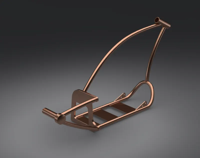
While designing any automobile we have to first focus on the chassis. Because it is the most integral part of the automobile that bears all the load of the automobile. While designing chassis for my American chopper I mainly used feathers like sweep, dome, boss extrude and fillet.
I firstly started with sketches and after that by using projected curve I managed to merge these sketches together and did sweep on that like blueprint. While creating a geometry which cannot be sketched in one plane projected curve feather helps a lot for creating such geometry. I mainly designed the chassis in tubular form because it provides good strength. Lastly for appearance I painted the chassis with Siena colour.
- ENGINE:
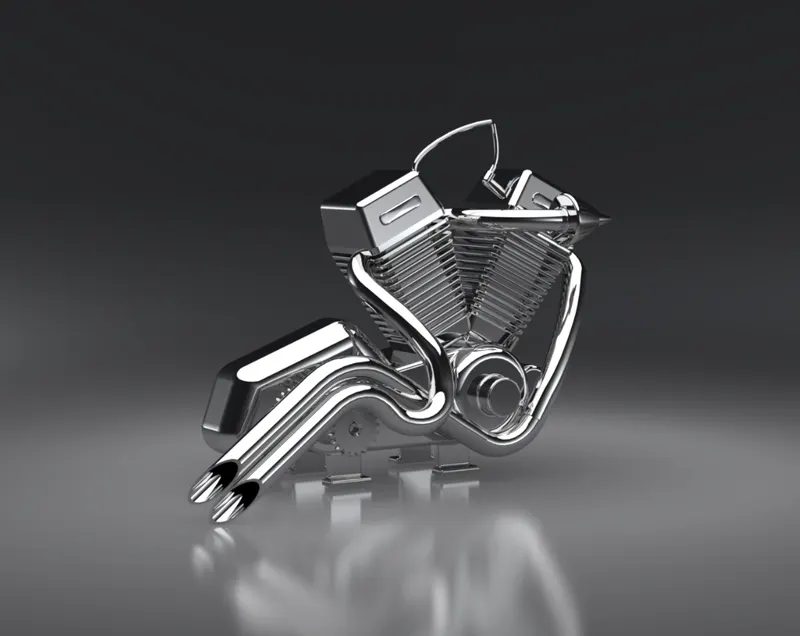
For me engine was the part that consume max time while designing the American chopper. As engine as whole is very complex part because it contains many individuals part of American chopper like starting motor, inlet manifold with filter, exhaust, chain sprocket and etc. Firstly, I started with boss extrude for cylinder block and then another extrude for cylinder head after that I modelled the fins with the help of linear pattern. For the base of the engine and starting motor I used boss extrude and fillet with proper dimensions and reference which from blueprint. While designing the inlet exhaust, I mainly used projected curve feather for merging two sketches into together and creating appropriate path for the sweep. Which later leads to create the inlet and exhaust. I also used spilt feature at the end of exhaust for crating the appearance like real exhaust. While designing the sprocket and filter for the inlet of the engine I used circular pattern which helped me a lot to save my time. At last for appearance I used chromium plate metal.
- FRONT FORK:
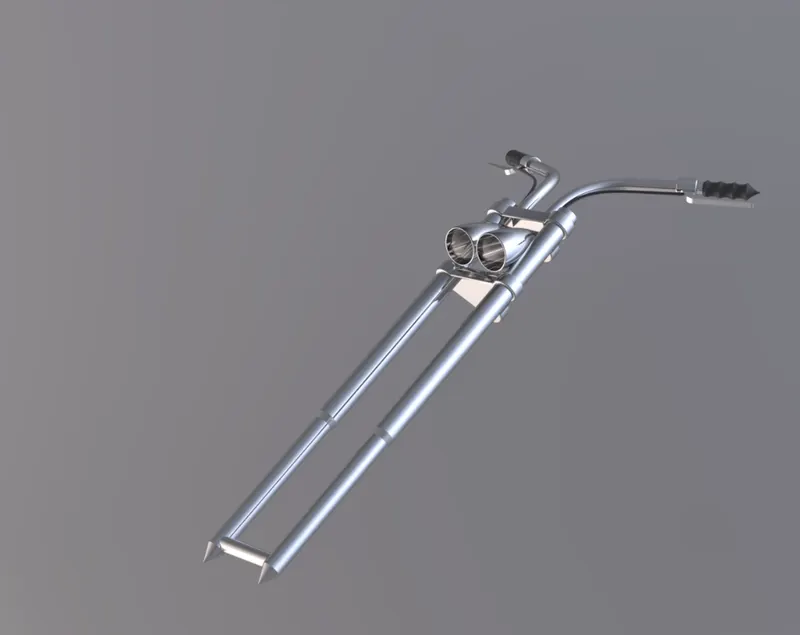
Front fork is the part which make the American chopper different from other bike because of its two long forks which keep front tyre away from the whole bike and give it a different look.
I started with designing the fork first by using revolve feather. I also used revolve feather for designing the headlight. For designing the handle, I had firstly created appropriate projected curve as per the ideation sketches and then with the help of sweep I modelled the handle. In similar manner I created the cables of front brake and clutch. For grips I used linear pattern. Then I mirrored the fork, headlight, handle, grip, cable, lever about the appropriate face which results in developing the full model of front fork. Mirror is the feather which I loved most during the designing of this part because it literally shreds my work into half.
For good appearance I applied chromium plate metal to forks, headlights and handle. For grips and cable, I preferred glossy rubber as appearance. Also, for realness I applied clear glass to the front of headlight.
- FRONT WHEEL:
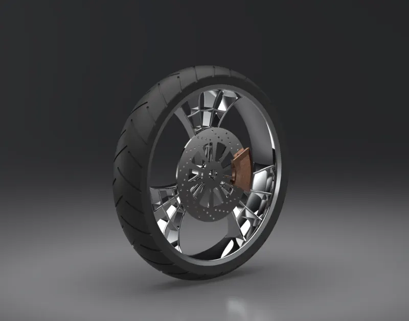
The front wheel is much thinner than rear wheel of American chopper. It is an multi body part which consists of rim, rotor, calliper and tyre. The design started with revolve feature for base of tyre and ended by creating the holes on rotor by the help of circular pattern. In between boss extrude, cut extrude, cut revolve, fillet and circular pattern are the other main feathers which were used for modelling the front wheel. At last calliper provided with Siena, rotor with chromium plate metal, rim with carbon steel metal and tyre with matte rubber appearance.
- REAR WHEEL:
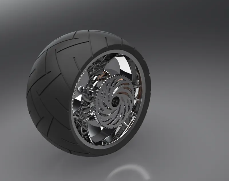
Rear wheel of an American chopper is multi body part consisting of rim, rotor, calliper, sprocket and tyre. Mostly used features for rear wheel were boss extrude, cut extrude, cut revolve, circular pattern. The appearance provided was also same as the front wheel other than the sprocket which was provided with chromium plate metal.
- FUEL TANK:
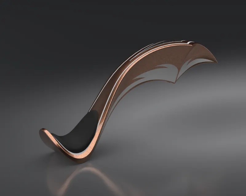
The fuel tank of American chopper is not similar to the other traditional bike fuel tank. It is a long curvy fuel tank which give it a different look. The fuel tank is designed as per the ideation, the main feathers used while designing were the surface loft, fill surface, boundary surface, etc. The fuel tank was made hollow by using shell feather for storing fuel. A trademark low seat was also designed along with this. After applying the Siena appearance i applied few decals for improving austenitic of bike. The seat was given cloth appearance.
- OIL TANK:
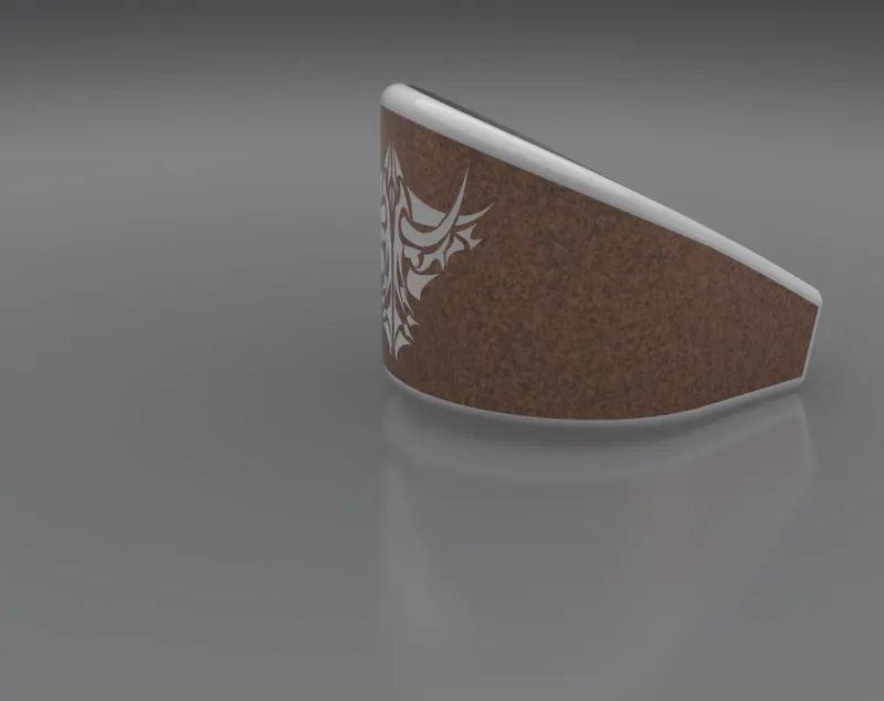
Oil tank was created as per the ideation sketches and placed above the engine block. It was also made hollow. Boss extrude, shell were the major feathers used for designing the oil tank. Siena with white border was applied as the appearance.
- FRONT FENDER:
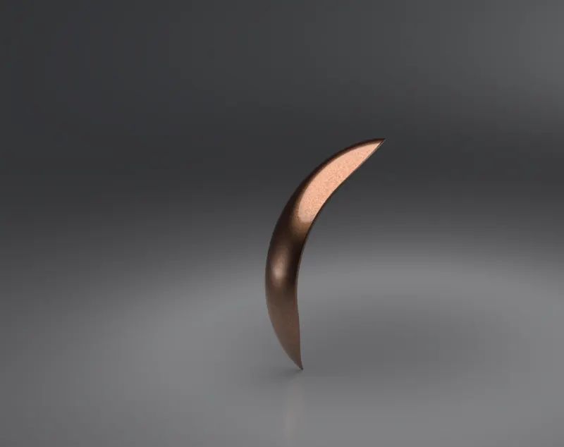
Front fender was created by using revolve feather and then used split feature for making its ends pointed. Siena was applied as appearance to this part.
- REAR FENDER:
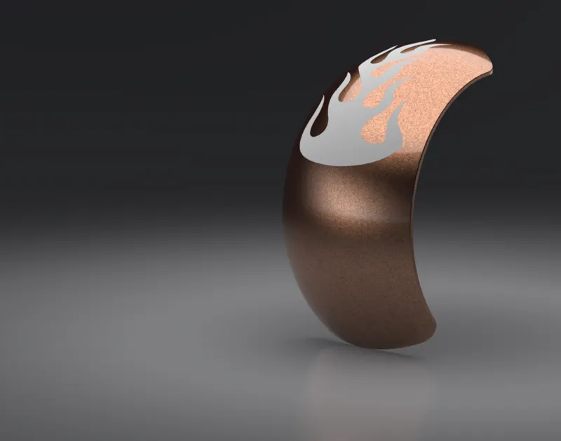
Rear fender is same as front fender having small length. It doesn’t have pointed ends as like front fender. Revolve and spilt were the major features for designing the rear fender. Siena was applied as the appearance for this part.
- CHAIN:
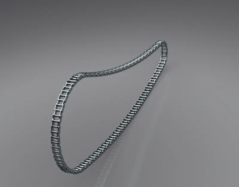
Chain is used for transmitting the power from engine to the rear wheel. While designing chain I first started with the crating sketches for two chain links and then converted them into two different blocks. Creating block made my work easier because I don't need to draw them again and again whenever I need then I can simply insert the blocks. After that I extruded the chain links. Due to the curvy nature of chain I had to extrude then 4 times for making the whole chain. Then I applied mirror to the chain links and completed the chain. While designing the chain i noticed that I had given more emphasis to the relation in this particular part than in any other part of the American chopper. Lastly, I applied chromium plate metal appearance to the whole chain.
- TRANSMISSION BELT:
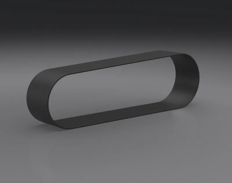
Transmission belt transfer the motion from the front pulley to rear pulley. It was simplest part it this project and created by only boss extrude. It was applied by matte rubber appearance.
- PEDAL:
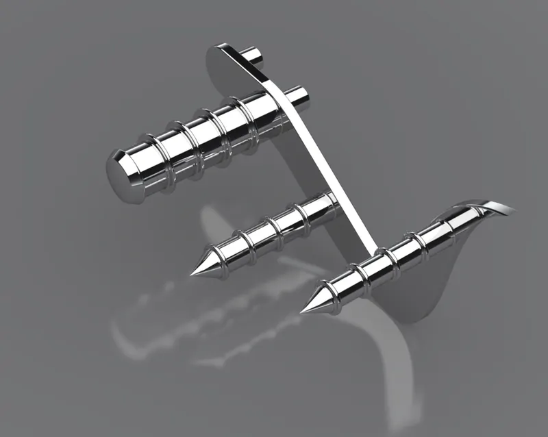
Pedal is the part which is useful for resting the foot while driving the bike. The major feather used for this part were boss extrude, revolve, chamfer and linear pattern. It is applied with chromium plate metal appearance.
- KICKSTAND:
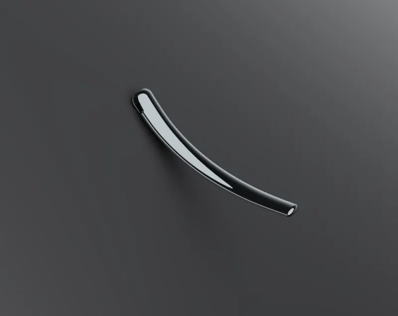
Kickstand is used for supporting the bike while parking. Kickstand was created by feathers like loft, cut extrude, spilt and dome, etc. It was provided by chromium plate metal as an appearance.
ASSEMBLY:
After creating the all parts alone, I had assembled them in assembly environment.
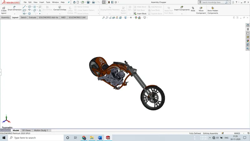
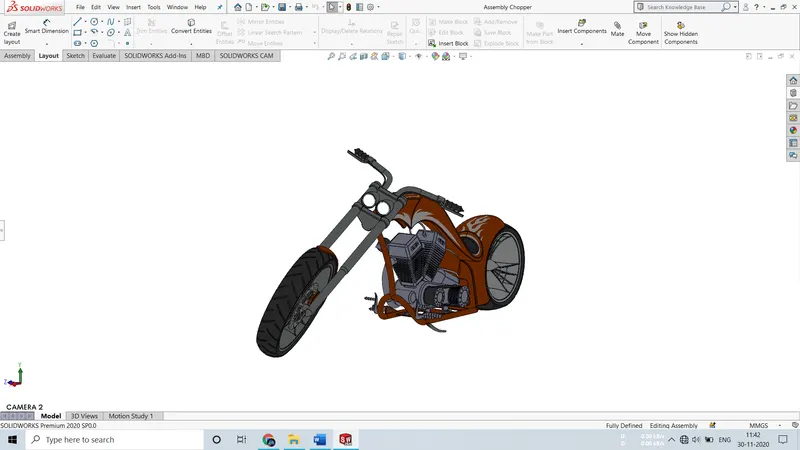
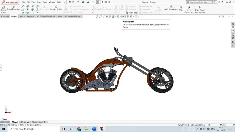
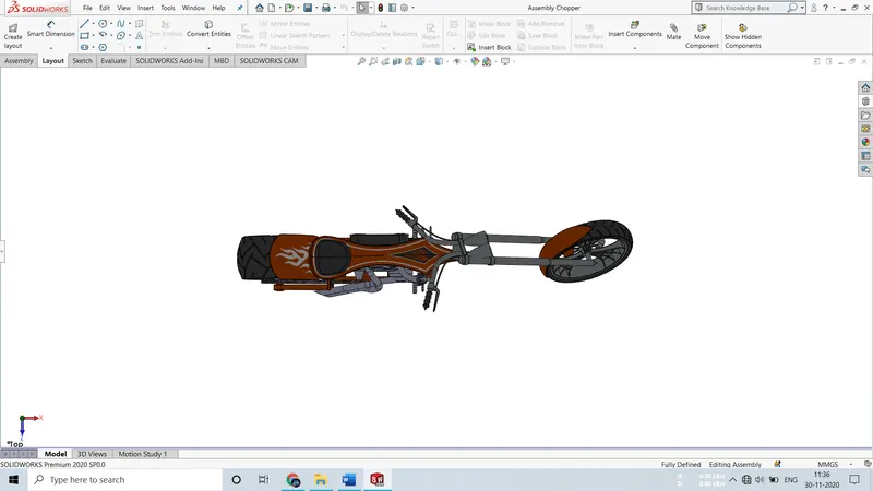
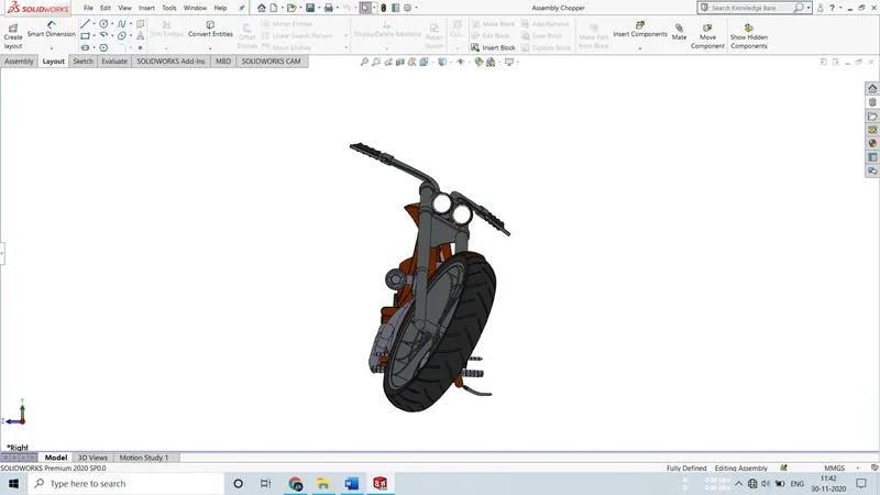
I started by first inserting chassis. The first insert in SOLIDWORKS is default fix so my chassis gets fixed automatically. Then I started insert components one by one. I gave them relation with respect to chassis so that if I move chassis they move together. For all the components I gave coincide relation with mid plane of chassis to their mid plane which ended up resulted in appropriate assembly. Coincident, concentric, distance, parallel are major mates that i had used during the mating. Mate is the feature which connects or join two different components. After inserting components, I had applied required mates to each part with respect to connecting part. SOLIDWORKS assembly environment gave us freedom to edit part in assembly itself or by opening it whenever there is an interference between them. While assembling the American chopper I found some interference in the parts which I solved one by one. Firstly, there was an interference between exhaust pipe and the chassis which resolved by editing the exhaust pipe. Another interference occurred between chain and chassis which resolved by editing the backplate and creating a slot there.
I also used features from assembly environment which gave me freedom to mirror the parts. I mirrored the pedal about midplane chassis and create my other side pedal.
Isometric view:
Camera setup view:
Front view:
Top view:
Right hand side view:
RENDERING:
In today's world aesthetics play a vital role. It is the aesthetics which make the impression in the customers eye other than technical features of the product.
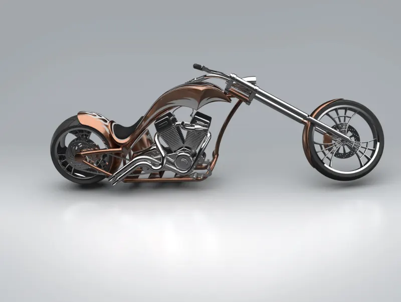
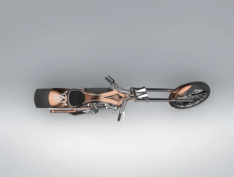
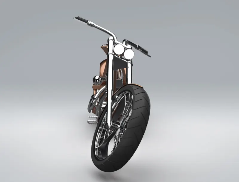
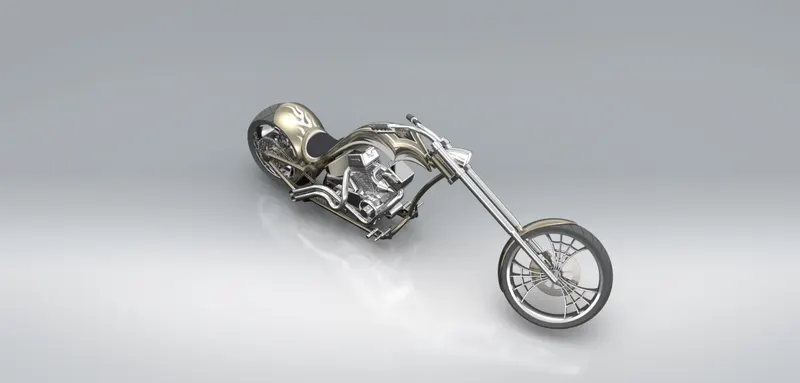
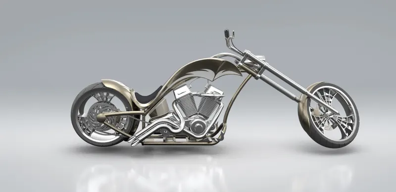
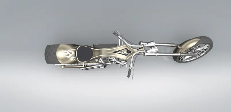
In rendering for applying decals and setting the camera view I mainly used photo view 360 which is inbuilt feather of solidworks and for the final image render I used another software from SOLIDWORKS which is SOLIDWORKS visualize which is able to render extremely high-quality images.
Rendered images of American chopper:
Camera setup view:
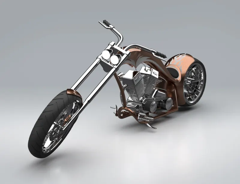
Isometric view:
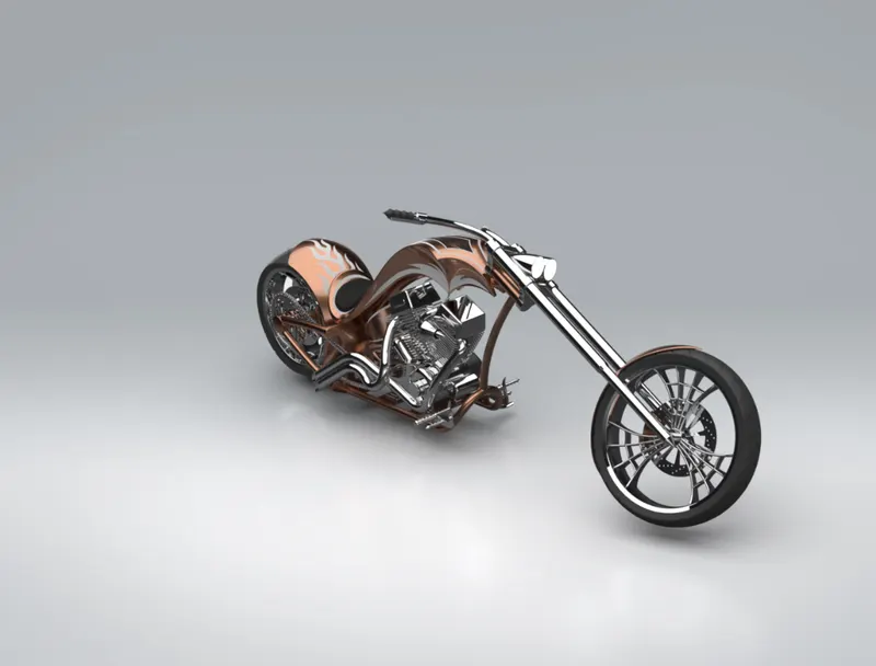
Front view:
Top view:
Right hand side view:
Additional renders:
CONCLUSION:
Successfully ideated, designed, assembled and rendered the American chopper bike. learned solidworks software as a design tool in industrial manner. This project really helps me to enhance my designing skill and help me to become industry ready for the role of Mechanical Design Engineer. Overall, the project was successful.