Roof challenge
Aim:
For the Given Roof styling and to Develop the essential flanges and reinforcements, Provide appropriate dimension and check for Draft analysis and also submit your section modulus report on the 0-Y section.
Do a curvature study on the roof and perform calculations to determine the position of the Bow-roof with the given requirements.
Software used:
NX CAD
Introduction:
An automobile roof or car top is the portion of an automobile that sits above the passenger compartment, protecting the vehicle occupants from sun, wind, rain, and other external elements. Because the earliest automobiles were designed in an era of horse-drawn carriages, early automobile roofs used similar materials and designs.
Objective Handled:
- For the given roof styling and master section, developed the essential flanges and reinforcements, provide appropriate dimensions and check for the Draft analysis and also submit section inertion analysis report on0-Y Section.
- Creation of roof ditch area the tool opening angle is only 3 to 5 degree.
- Design and develop roof rails as per the given master sections.
- Perform section modulus study for the master sections created for the front roof rail, rear roof rail, bow roof rail and rear roof rail
- To do a curvature study on the roof and perform calculations to determine the position of the Bow- roofs.
- To perform Heat distortoin criteria and snow load criteria tests on the designed roof and do optimization if necessary.
Theory:
The conventional task of the roof panel is that of compartment shielding, passenger protection and connection of body sides, front and roof cross members. In case of roll over, compartment integrity is provided by the compartment frames, the roof target is only to avoid the ejection of passengers, providing protection against hard local contact.
Another task of roof bows is to support the interior roof liner which requires a number of fittings both in central and boundary areas to avoid deflections and vibratioins. Fitting are usually plastic clips or velcro strips. Some roof liners, mostly on less expensive vehicle are bonded directly to roof panel.
Design of Roof:
- Roof rails are placed on the top of the vehicle and are used to carry additional luggage and equipment.
- Aluminium extrusions are used for manufacturing roof rails because they enable visually attractive, low weight and high strength designs.
- The length of aluminium roof rails can vary significantly, they are found on small cars as well as on station wagons and MPV's (Multi Purpose Vehicles). Roof rails have two principle functions
- to enhance the design features of the vehicle
- To carry extra loads placed on the roof, often with the help of another structure. e.g. transverse load bars or a roof box.
- Roof rail for looks and extra load support
- The typical roof rail has two cast supports with an extruded aluminium bar between them. It is also common to use an intermediate support for longer rails or where the design loads are high.
- It is act as reinforcement of front roof area & its design factor tp maintain the visibility criteria, headroom area & the space required for the windshield glass, rubber pad & sealent.
- Minimum thickness should be maintain of 0.75mm and the minimum reinforcement thickness is 1.5mm.
Ditch area:
The ditch area is the extended portion of the main roof sealed by the BIW panels. It acts with respect to the head clearance room and visibility criteria. the same ditch is created at front and back of styling roof. The thickness of the panel is 0.75mm.
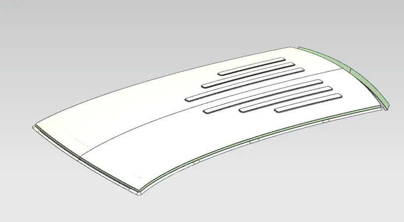
ISO View ROOF
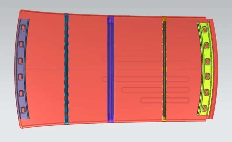
Bottom view of ROOF
Front Roof Rail:
To design a front roof rail we should have some basic knowledge of dimensions to convert the master section to a design with the appropriate dimentions to get the desired output. It is support which is joined with the wind shield glass, body side outer and the inner panels. It is made from the body side outer and its thickness of the rail is 0.75mm. The draft angle is 3 degree is provided with the given deep drawing analysis. The bottom flange is decided after taking into considerationof visibility criteria and the head clearance of passanger. Spot welds are assigned to the wind shield end of the rail and the other end is joined with the roof by Mastic sealents.
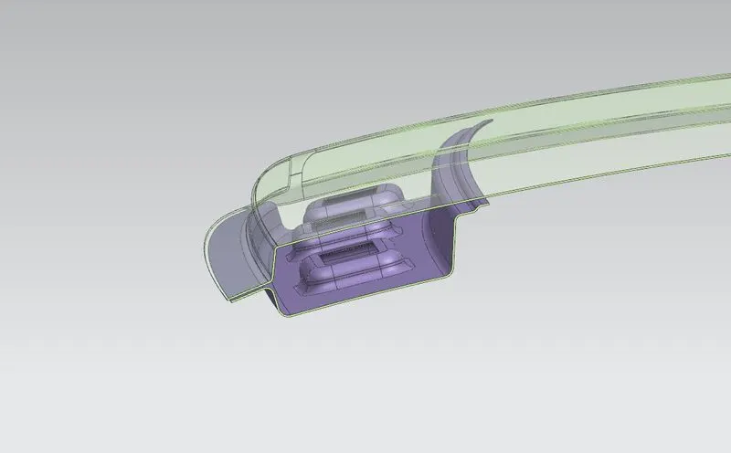
Front Roof rail
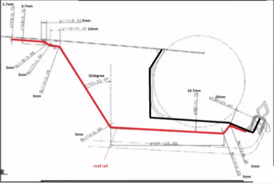
Below figure shows the master section of the front roof rail and the roof.
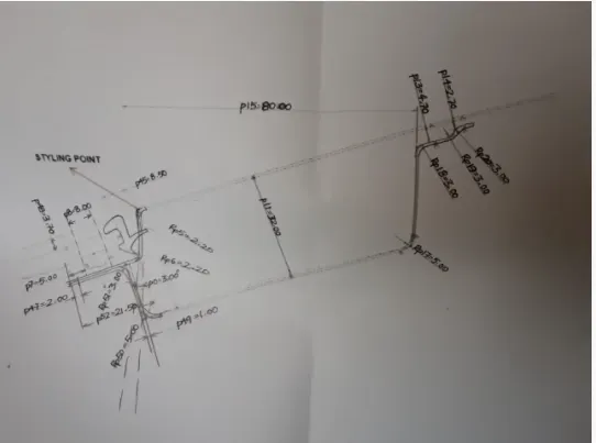
- The windshield is accomodated in the front of Front Roof Rail which is 3.70mm.
- Below the windshield, mastic rubber seals are provided which is 8mm thick. This rubber seals are provided to avoid breakage of windshields
- To below the rubber seals 2mm clearence is given to with respecte to the accomodate commodities by the trim teams.
- Rubber sealents are used which is 8.50mm thick to hold the windshied on the roof.
- To maintain the deep drawing criteria 3 degree angle should be maintain from the styling point. We can't be able to draw the parts if there is anything above 3 degree. Because of the visibility criteria should follow.
Rear Roof Rail:
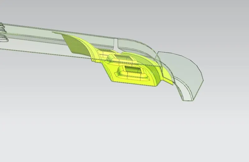
Similar to the front rail design, we have to take into consideration the rear Headroom clearence and the rear visibility criteria while designing the rear roof rail inputs from the backdoor design is also taken to accomodate the required clearance. Spot welds are applied at the back door end of the rail and the other end is joined with the roof using Mastic Sealents.
Rear Roof rail
Bow and Centre Roof rail:
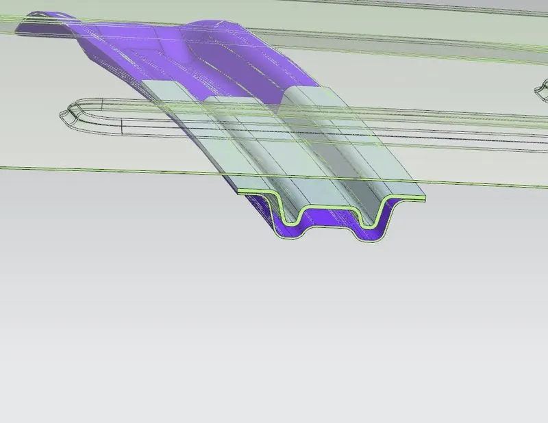
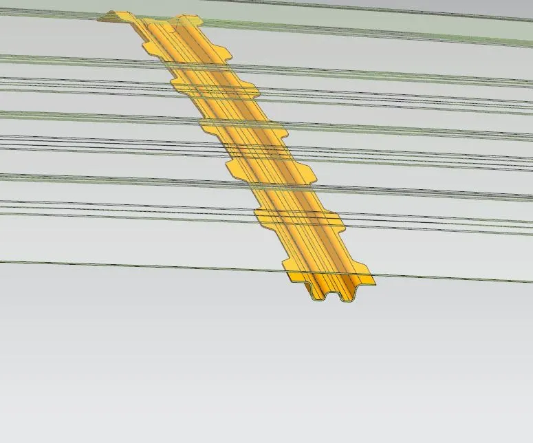
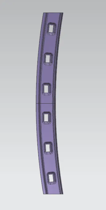
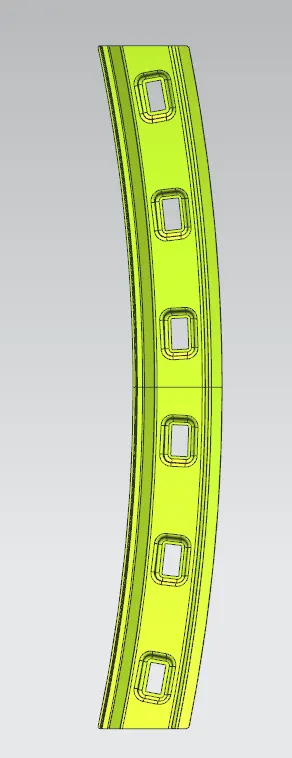
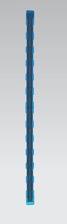
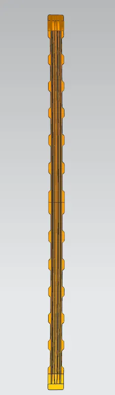
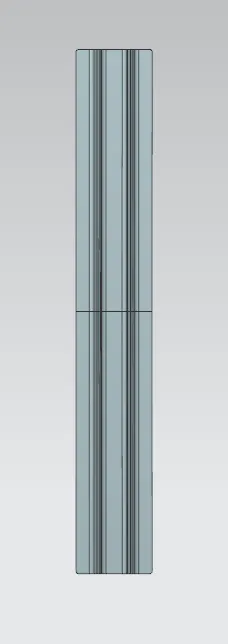
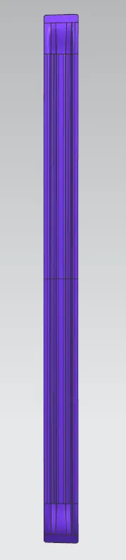
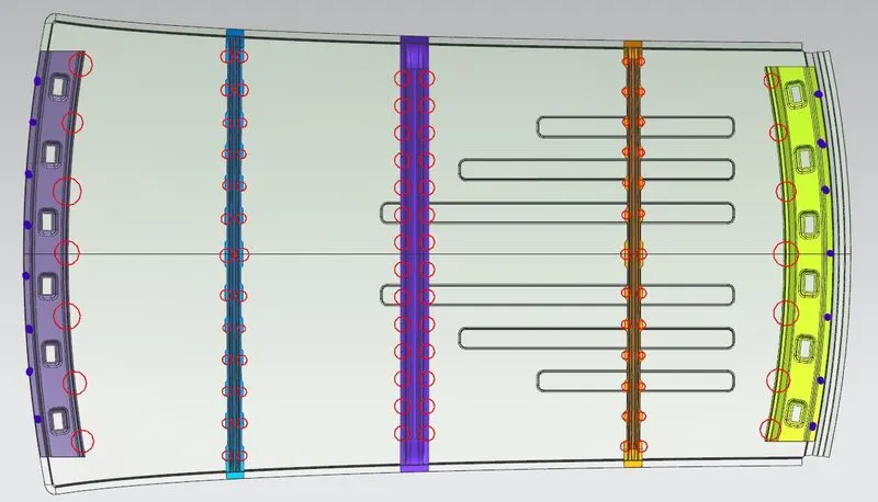
Similar to other rail designs, we have to take into consideration the headroom clearance and the visibility criteria while designing the centre roof rail and Bow roof rail. Spot welds are not applied for joining these roof rails to the roof. Instead mastic sealents are used at both the ends when Center roof rail, Bow roofs and centre reinforcement are fully positioned under the styling surface of the roof. For increasing the strength of the rails, embossing is done. the thickness of the bow roofs are 0.75mm.
Centre Bow Roof and Centre Reinforcement
Bow Roof 1
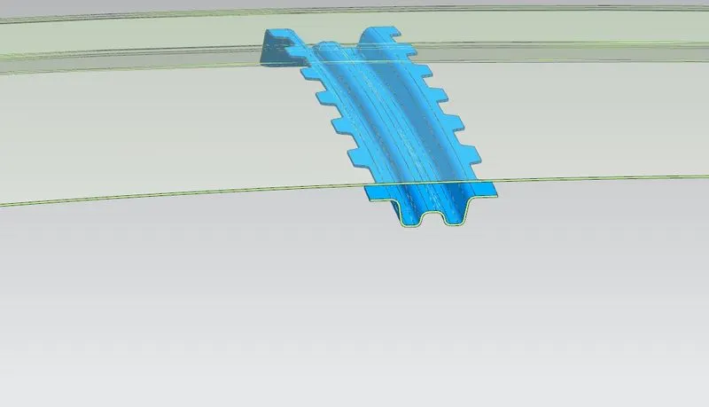
Bow roof 2
Mastic Sealents and Spot Welds:
Section inertia analysis:
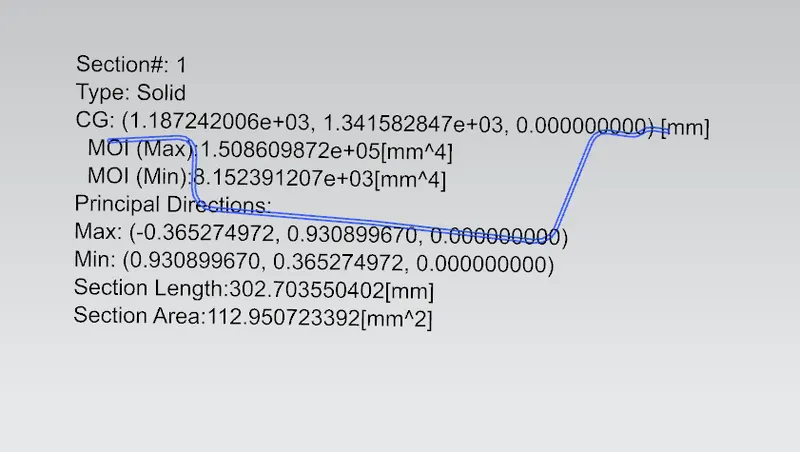
Front roof rail
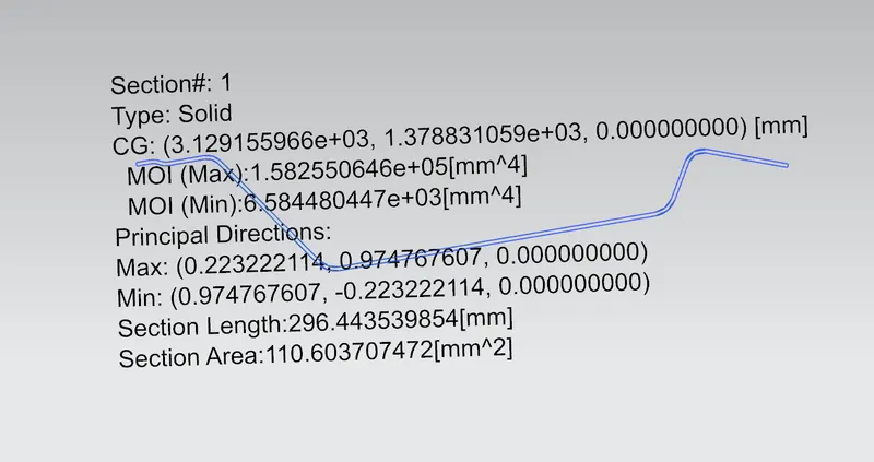
Rear roof rail
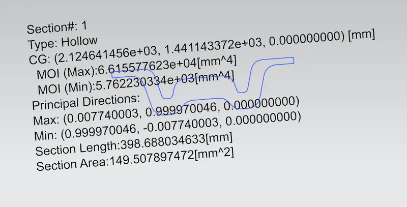
Center reinforcement
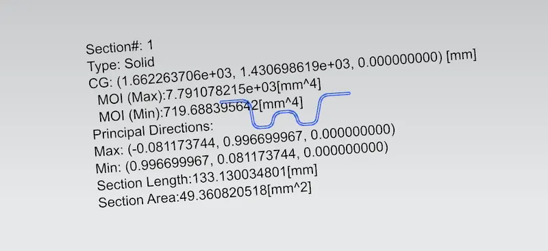
Bow roof 1
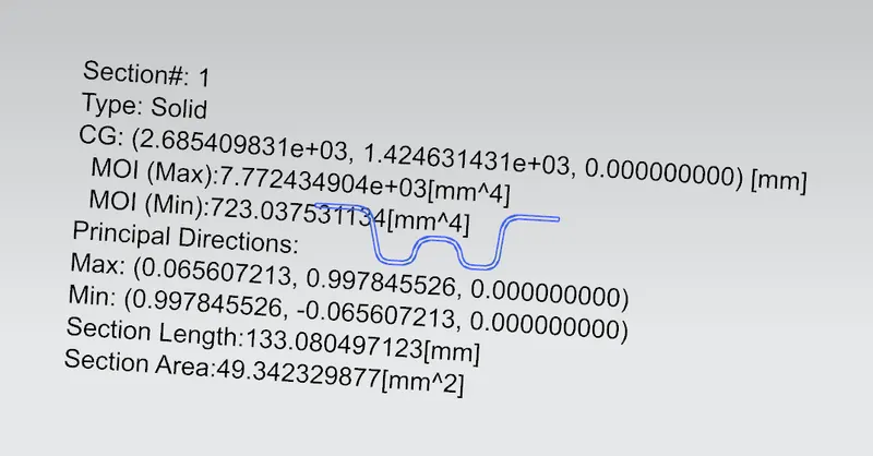
Bow roof 2
Draft Analysis:
The Draft Analysis command enables you to detect if the part you drafted will be easily removed. This type of analysis is performed based on color ranges identifying zones on the analyzed element where the deviation from the draft direction at any point, corresponds to specified values.
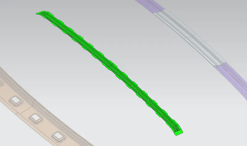
Bow Roof 1
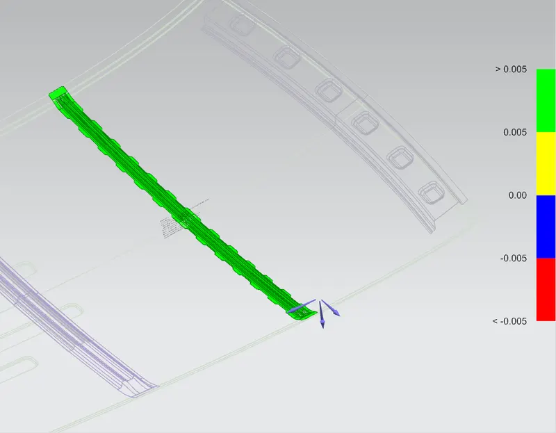
Bow roof 2
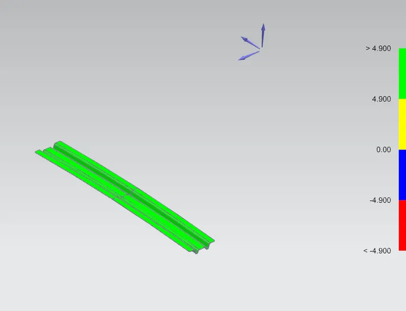
Center reinforcement
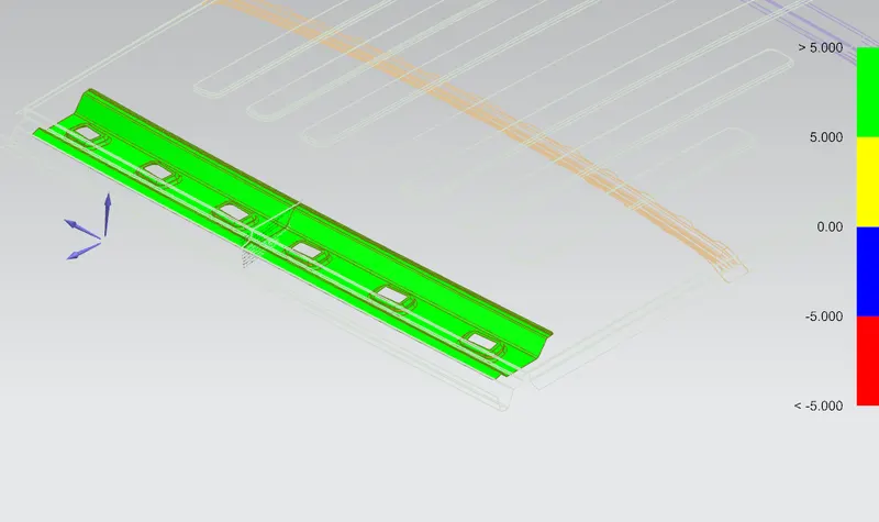
Rear Roof rail
Embosses in Roofs:
Embosses are given to improve the strength of the roof.
Embosses also provided for styling purpose and to improve the aerodynamics.
Heat Distortion:
Heat distortion test is a static load test which plays a major role to maintaining the roof strength. From Heat distortion criteria, roof strength can be enhanced by appropriate positioning of bow roof rails.
W = [1.73 x 10^(-3) x L] + [1.85 x 10^(-8) x (R^2)/t] + [ 1.10x10^(-3) x l] - 2.68
Judgement Condition : OK< 2.7> 3.1
Where
L = Roof Length in X-Direction[mm](Roof dimension in 0-Y)
R = Roof curvature
R = 2(Rx*Ry)/(Rx+Ry)
Rx = X curvature
Ry = Y curvature
t = Roof plate thickness [mm]
l = Bow Roof Span [mm]

From the above table, it can be concluded that this design would clear the heat distortion criterion. because of all values of W are less than 2.5.
Snow Load:
Qr = [Iy x t2] / [α x s x [(Rx + Ry)/2]2 x 10-8]
Note: The Qr value given over here is correct. There was a typo error in the formula given in the video.
Where
α = My x Lx2 x 10-12 , My = Y(Ly-Y)
Judgement condition = Qr ≥ 3.1
250 ≤ s ≤ 380
t = Roof plate thickness [mm]
Ly = Distance between the front and rear roof Rails on the Vehicle along with 0Y[mm]
Length of Roof panel with the center point between Roof rail Front /Rear as the reference point of the front and the rear.
Lx = Distance between the Left and Right end of the roof on the Roof BOW [mm]
Width of the roof panel exposed on the surface.
Y = Distance front Front Roof Rail to Roof BOW[mm]
s = Distance for which Roof BOW bears divided load [mm]
s = L1/2 + L2/2
Iy = Geometrical moment of inertia of Roof BOW (Y cross-section )[mm4]
Rx = Lateral direction curvature radius of roof panel Y cross-section on Roof BOW [mm]
Roof panel curvature Radius of the Length Lx in Front view
Ry = Longitudinal Direction curvature radius of the Roof panel X cross-section on Roof BOW [mm]
Roof panel X curvature radius of length s in Side view

The values of Qr is greater than 2.5, this design clears the snow load criterion.
Conclusion:
For the Given Roof styling, the roof and ditch area is succeessfully designed, along with the heat distortion test and snow load test and checked for Draft analysis and also submited section modulus report on the 0-Y section has been done. So it could be sent to further steps of design validation.