Roof Challenge
ROOF DESIGN
An automobile roof or car top is the portion of an automobile that sits above the passenger compartment, protecting the vehicle occupants from sun, wind, rain, and other external elements.
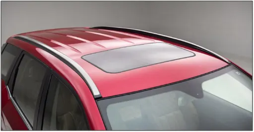
FIG 1. CAR ROOF
The Automobile roof consists of the following parts:
- The outer panel
- Front roof Rail
- Bow Roof
- Centre Roof Rail
- Rear Roof Rail
FRONT ROOF RAIL:
The front roof rail is created at the front side of the roof to provide strength to the roof. Headroom clearance and the driver visibility are the two important factors to be considered while designing the front roof rail. the front roof rail is connected to the roof outer panel with the help of mastic seal.
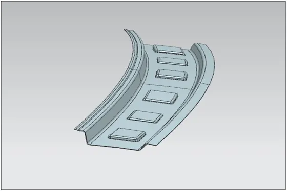
FIG 2. FRONT ROOF RAIL
BOW ROOF:
It is used to give strength to the area between the front roof and the centre roof rail. Also it is created in the area between the centre roof rail and the rear roof rail to provide enough strength. It can be created in any numbers depending upon the roof length but the position of the bow roofs is to be justified by curvature study.
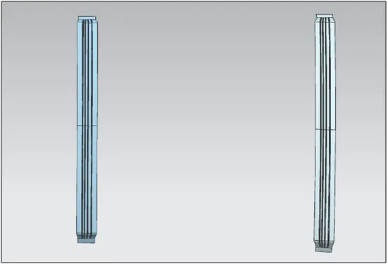
FIG 3. BOW ROOF
CENTRE ROOF RAIL:
It is created at the centre of the roof. It is connected to the roof by mastic seal.
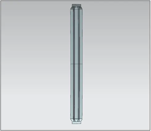
FIG 4. CENTRE ROOF
REAR ROOF RAIL:
It is created at the rear end of the roof. The fitment of the backdoor is to be considered while designing the rear roof rail.
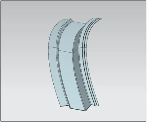
FIG 5. REAR ROOF RAIL
ROOF IMAGES:
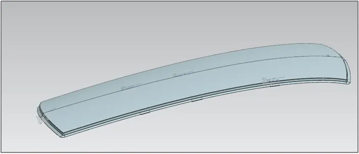
FIG 6. ROOF IMAGE 1
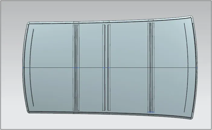
FIG 7. ROOF IMAGE 2
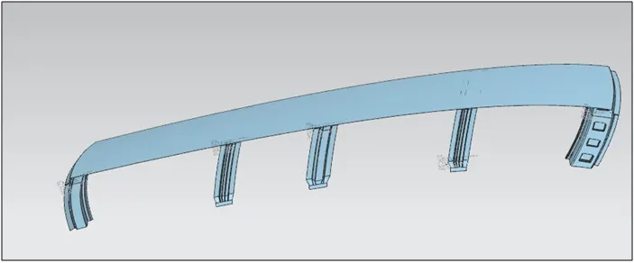
FIG 8. ROOF IMAGE 3
HEAT DISTORTION CRITERIA:
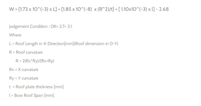
Heat distortion temperature is the temperature at which metal softens and deforms under a specified load. While designing roof, this criteria is taken into consideration. We create bow roofs when the roof is long and flat to increase its strength. The position of the bow roofs is to be justified and this justification is done by curvature study:
Bow - Roof prediction Formula
TO MEASURE L:
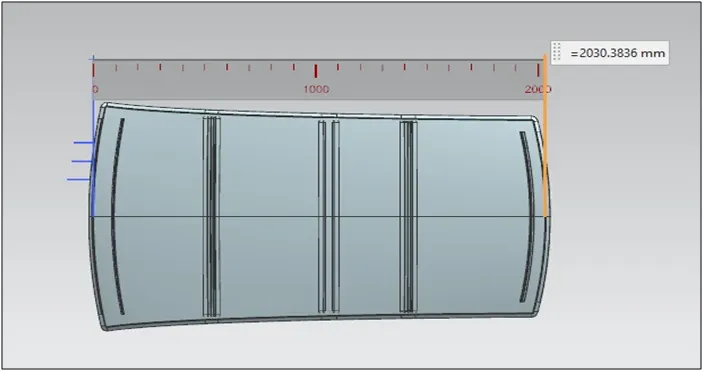
FIG 9: TO MEASURE L
TO MEASURE Rx:
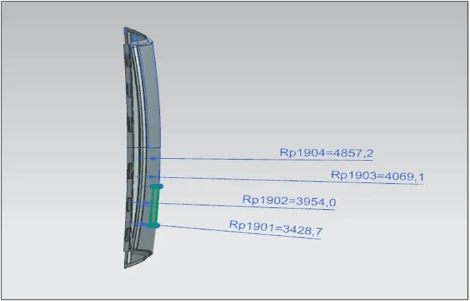
FIG 10. TO MEASURE Rx
TO MEASURE Ry:
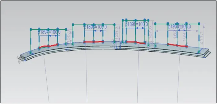
FIG 11. TO MEASURE Ry
TO MEASURE l (BOW ROOF SPAN):
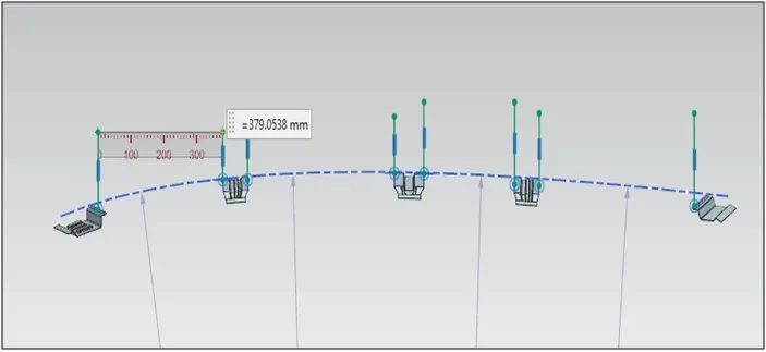
FIG 12. BOW ROOF SPAN
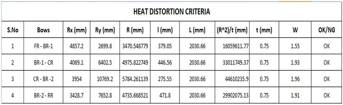
Here we can see that the roof is completely satisfying the conditions of heat distortion.
SNOW LOAD PREDICTION FORMULA:
Snow load is the downward force on a car's roof by the weight of accumulated snow and ice. The roof can fail if the snow load exceeds the weight the roof was designed to shoulder. Or if the roof was poorly designed or constructed.
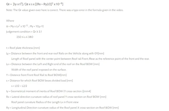
So there is a formula to predict the strength of the roof.
TO MEASURE Ly:
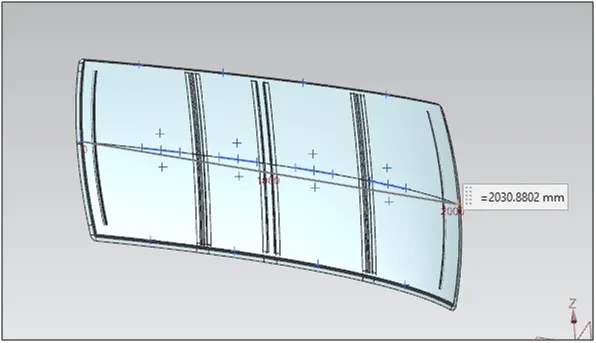
FIG 13. MEASURING Ly
TO MEASURE Lx:
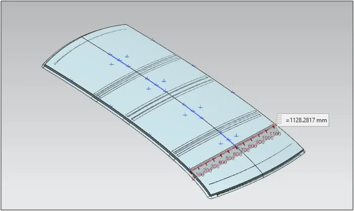
FIG 14. MEASURING Lx
TO MEASURE Ry:
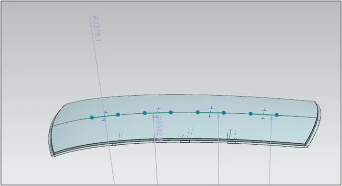
FIG 15. MEASURING Ry
TO MEASURE Rx:
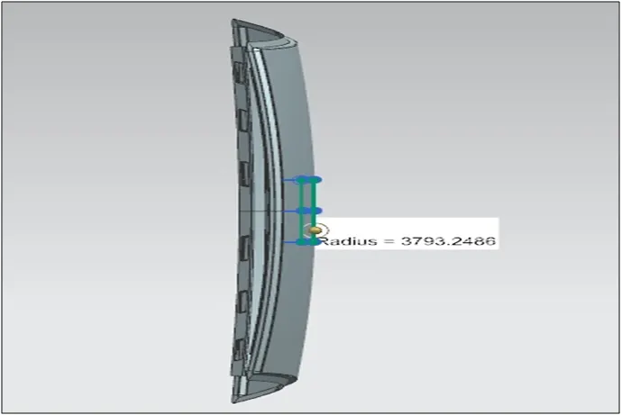
FIG 16. MEASURING Rx
TO MEASURE s:
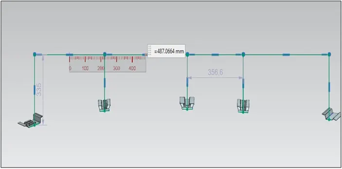
FIG 17. MEASURING s
TO MEASURE Y:
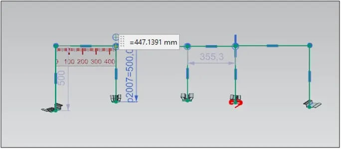
FIG 18. MEASURE Y
After calculating all these values the Qr is found out.
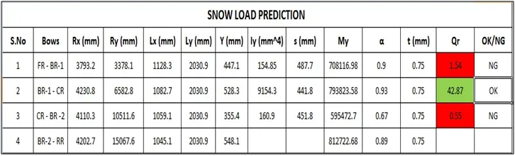
It is observed that the roof is satisfying the condition only in the area between bow roof 1 and centre roof. in the other areas it is not satisfying the condition. So in order to strengthen the roof at these areas embosses are created on the outer roof.
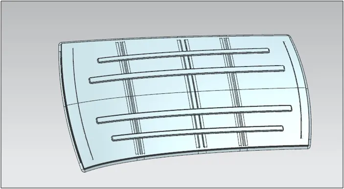
FIG 19. EMBOSS TO STRENGTHEN THE ROOF
SECTION MODULUS STUDY OF THE SECTION OF THE ROOF RAILS:
The section modulus of the cross-sectional shape is of significant importance in designing of structures. It is a direct measure of the strength of the structure
A structure that has a larger section modulus than another will be stronger and capable of supporting greater loads.
Section modulus (S) = I/y
Where,
I = Moment of inertia in (mm4)
y = Distance between the neutral axis and the extreme end of the object (mm)
FRONT ROOF RAIL:
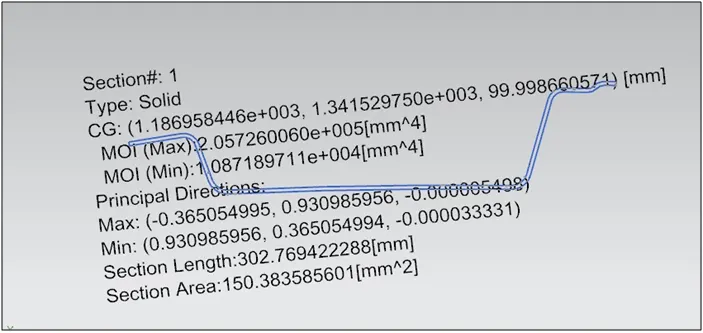
FIG 20. FRONT ROOF RAIL SECTION INERTIA ANALYSIS
I = 10871.9 mm^4
y = 114.28mm / 2 = 57.14mm
S = I/y = 190.27mm^3
BOW ROOF 1
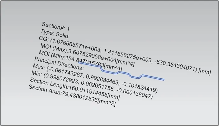
FIG 21. BOW ROOF 1 RAIL SECTION INERTIA ANALYSIS
I = 154.8 mm^4
y = 74.97mm / 2 = 37.49 mm
S = I/y = 4.13mm^3
CENTRE ROOF RAIL:
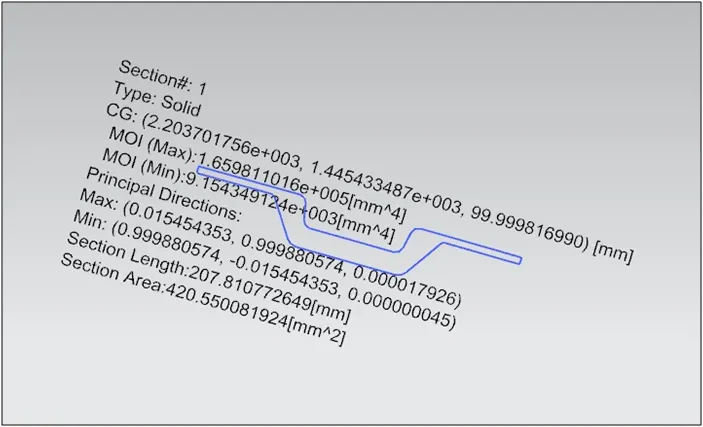
FIG 22. CENTRE ROOF RAIL SECTION INERTIA ANALYSIS
I = 9154.3 mm^4
y = 89.99mm / 2 = 44.99 mm
S = I/y = 203.45mm^3
BOW ROOF 2
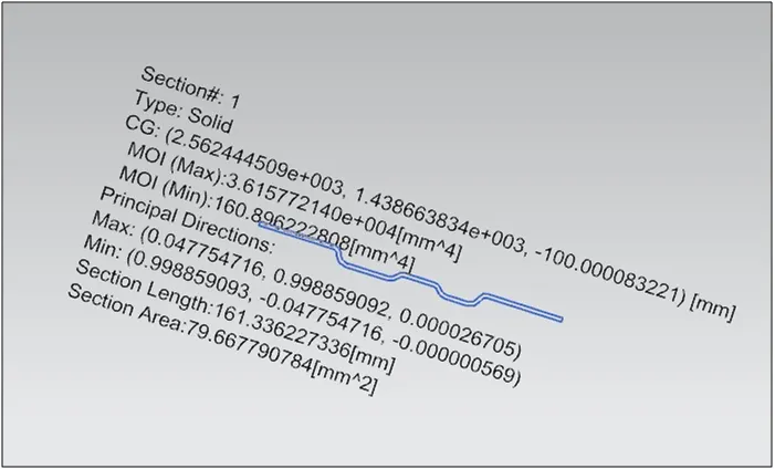
FIG 23. BOW ROOF 2 RAIL SECTION INERTIA ANALYSIS
I = 160.89 mm^4
y = 75.84mm / 2 = 37.92 mm
S = I/y = 4.24mm^3
REAR ROOF RAIL:
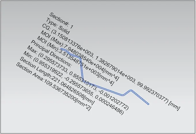
FIG 24. REAR ROOF RAIL SECTION INERTIA ANALYSIS
I = 3513.54 mm^4
y = 91.73 mm / 2 = 45.86 mm
S = I/y =76.61mm^3
DRAFT ANALYSIS:
In NX to check whether the sheet metal part we have designed can be deep drawn, there is an option called draft analysis. This type of analysis is performed based on color ranges identifying zones on the analyzed element where the deviation from the draft direction at any point, corresponds to specified values.
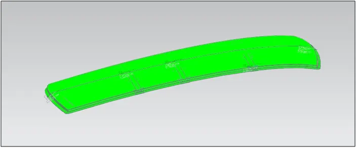
FIG 25. ROOF DRAFT ANALYSIS
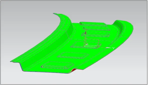
FIG 26. FRONT ROOF DRAFT ANALYSIS
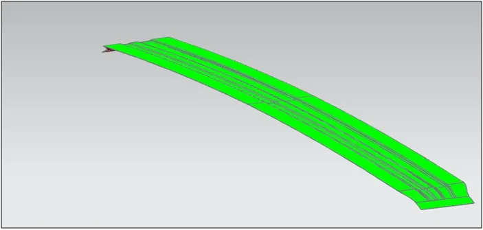
FIG 27. BOW ROOF 1 DRAFT ANALYSIS
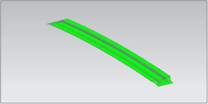
FIG 28. CENTRE ROOF RAIL DRAFT ANALYSIS
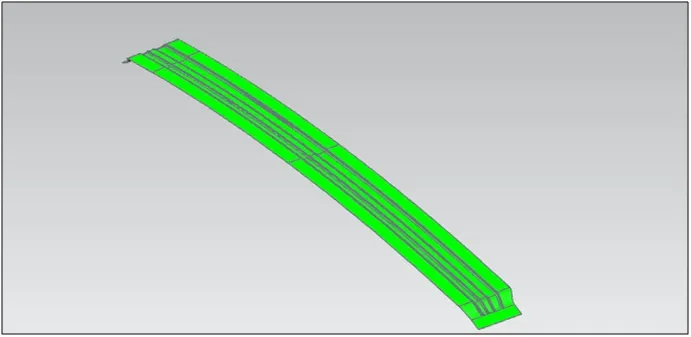
FIG 29. BOW ROOF 2 DRAFT ANALYSIS
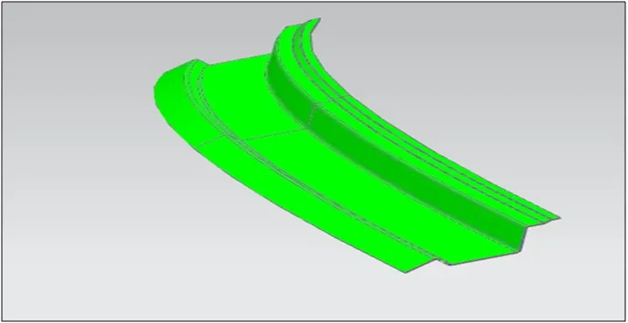
FIG 30. REAR ROOF RAIL DRAFT ANALYSIS
*********