Roof Assembly Design
INTRODUCTION
An automobile roof is a component that is mounted above the passenger cabin saving passengers from sun, rain and debris. The roof surface provides aerodynamics to the car. It sometimes features a sunroof which is a small glass pocket made in the roof to let the sunlight in the cabin. This roof is made up of the same material as the other body parts.
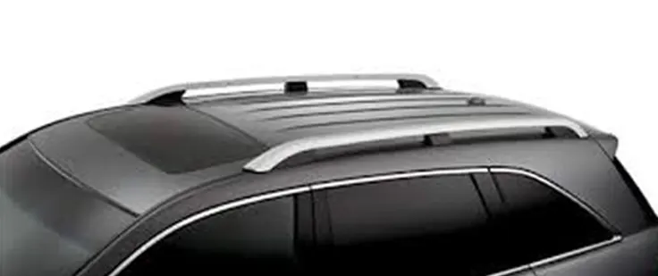
Designing the roof is a critical challenge for design engineers. They must consider different design parameters such as front and rear visibility criteria for the passengers, cabin head room, heat distortion criteria, snow load criteria etc. In this project a roof panel is provided. The objective of the project is to create front roof rail, roof bows, and rear roof rail from the given master sections.
Given master sections-
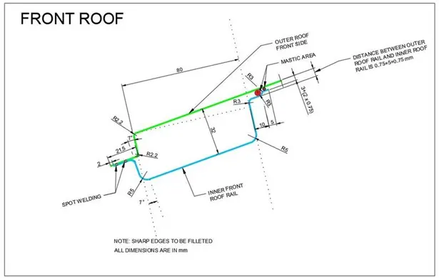
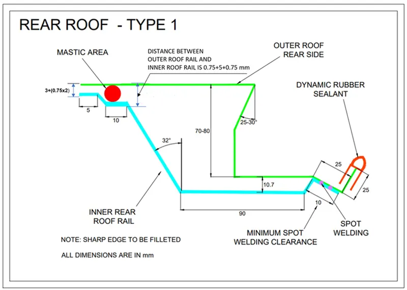
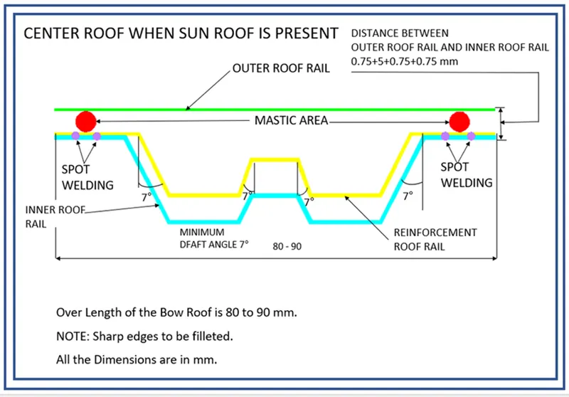
Given outer panel-
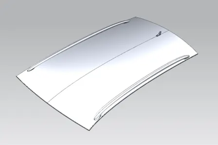
In this roof design a sunroof is considered, hence an extra reinforcement roof bow is added. These roof rails and roof bows provide support to the roof and are joined onto the roof outer panel using mastic sealant. Following are the images of the designed roof rails and roof bows.
1. Front roof rail-
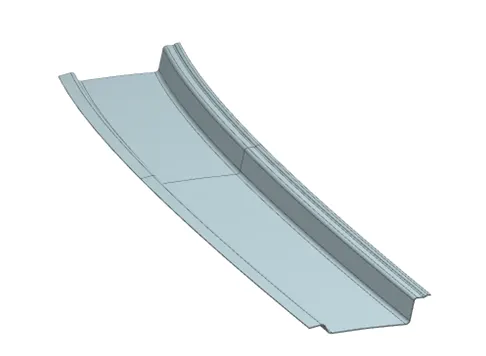
2. Bow Roof 1-
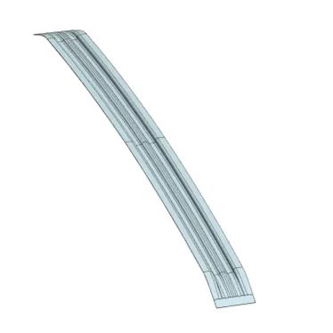
3. Reinforcement Roof Rail
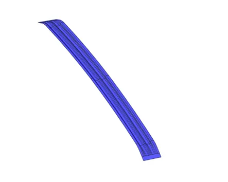
4. Bow roof 2-
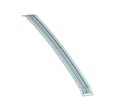
5. Rear Roof Rail-
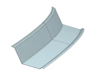
6. Roof Outer Panel
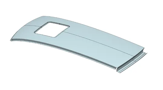
Overall design and component positions-
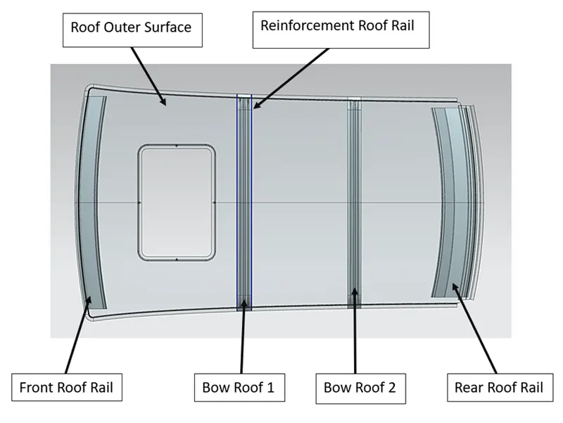
Positioning of roof rails
The car is subjected to different stress and loads in circumstances acting directly onto the roof. To avoid bending of the roof the designer must place the roof rails in such positions as to prevent failure at any point on the roof.
Front roof rail and rear roof rails are at the front and rear position of the roof respectively. Whereas, to determine the position of the roof bows two formulas for (Heat distortion criteria & Snow load criteria) are used.
Heat distortion criteria:
The modern cars are more inclined to reducing weight and increasing fuel efficiency. One of the ways to achieve this is by reducing the usage of steel or aluminium in the car body. The thin metal sheets are effective for this purpose. But, in the manufacturing phase electrodeposition the car goes to drying process where hot air is passed onto it. This heat from the air causes a distortion (thermal distortion) on the body. The rectification and repair work results in more labour hours and thus increasing the manufacturing cost. Thus, the heat distortion is evaluated at the designing phase.
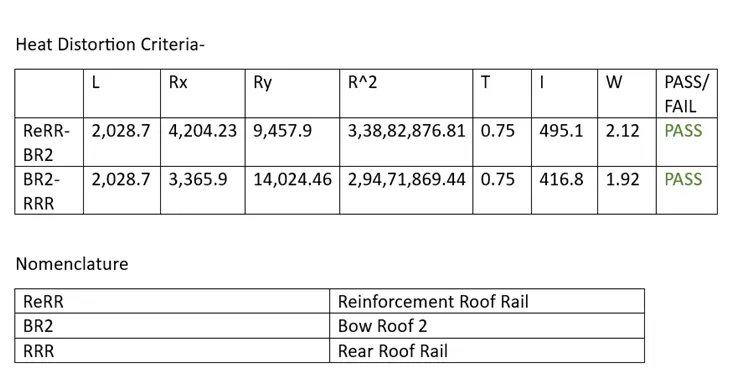
Similarly, in countries where the temperatures go beyond consideration, the metal as its property, tends to expand. Once the roof although minimally expands its strength is also compromised. Hence, design engineers consider a formula wherein the calculated value should be within the range. If not, then the positions of the roof bows must be changed.
Formula:
W = [1.73 x 10^(-3) x L] + [1.85 x 10^(-8) x (R^2)/t] + [ 1.10x10^(-3) x l] - 2.68
Where,
L = Roof Length in X-Direction[mm](Roof dimension in 0-Y)
R = Roof curvature = 2(Rx*Ry)/(Rx+Ry)
Rx = X curvature
Ry = Y curvature
t = Roof plate thickness [mm]
l = Bow Roof Span [mm]
Judgment Condition
OK< 2.7
Calculating the variables:
A. Calculating the Rx and Ry value-
Step 1:
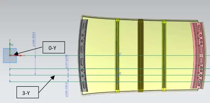
For this calculation a horizontal line from 0Y is drawn passing through the centre of the roof. From that 0Y line another line (3Y) at 300mm is drawn parallelly under it. This 3Y line is offsetted symmetrically at 100mm each.
Step 2:
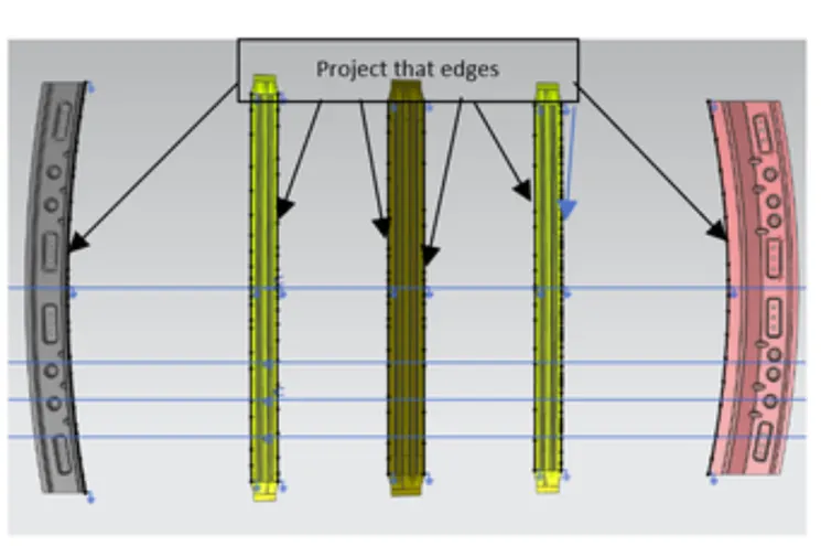
With the help of project curve option, following curves are projected.
Step 3:
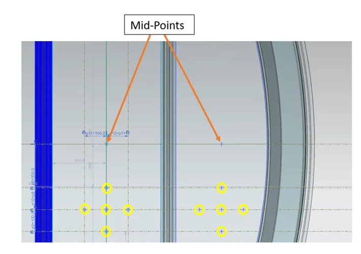
From the projected curve, a midpoint in between two bow roofs are created through which a passing line is drawn. The line is then offsetted symmetrically at 100mm each. From these three lines and the lines before, intersection points are created as shown in the picture.
Step 4:
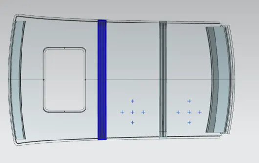
Now, these intersected points are projected onto the roof surface.
Step 5:
By using three-point arc option, arcs are created as shown. Check the local radius of each arc. The vertical arcs show Rx values whereas horizontal show Ry values.
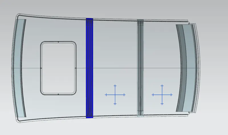
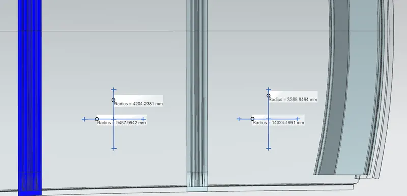
B. The L value and I values for both cases are shown as below.
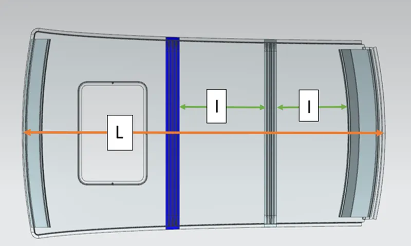
Since the roof has a sunroof the Bow Roof 1 and Reinforcement roof rail are at the same position from Y axis. Hence, the calculation for bow roof 1 is not needed and only reinforcement roof rail is taken into consideration.
Snow Load Criteria:
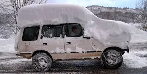
Snow load criteria refers to the load applied by the snow due to heavy snowfall on the car roof. To test it in-house heavy loads are attached to the roof from inside. If the roof is pulled in due to weights, then the roof bow positions should be changed. It is also tested by the CAE team. Before the tests, a design engineer would use the following formula to match the needed value within range.
Qr = [Iy x t^2] / [α x s x [(Rx + Ry)/2]^2 x 10-8]
Where,
α = My x Lx2 x 10-12 , My = Y(Ly-Y)
t = Roof plate thickness [mm]
Ly = Distance between the front and rear roof Rails on the Vehicle along with 0Y[mm]
Length of Roof panel with the center point between Roof rail Front /Rear as the front and rear reference point.
Lx = Distance between the Left and Right end of the roof on the Roof BOW [mm]
The width of the roof panel is exposed on the surface.
Y = Distance front Front Roof Rail to Roof BOW[mm]
s = Distance for which Roof BOW bears divided load [mm]
= L1/2 + L2/2
Iy = Geometrical moment of inertia of Roof BOW (Y cross-section )[mm4]
Rx = Lateral direction curvature radius of roof panel Y cross-section on Roof BOW [mm]
Roof panel curvature Radius of the Length Lx in Front view
Ry = Longitudinal Direction curvature radius of the Roof panel X cross-section on Roof BOW [mm]
Roof panel X curvature radius of length s in Side view
Judgment condition
Qr ≥ 3.1
250 ≤ s ≤ 380
Calculating the variables:
Similar to the above sketches, a 0Y line is created passing through the centre of the roof. From the 0Y line two symmetric offsets are created at 100mm. The edges of the roof, roof rails and bow roofs are projected. By taking the mid-point in between each bow roofs and roof rails a line is drawn passing through it vertically. This line is offsetted symmetrically at 100 mm. At intersections needed points are created. For this particular criteria other midpoints of each, front roof rail, reinforcement roof rail, bow roof 2 and rear roof rail are created.
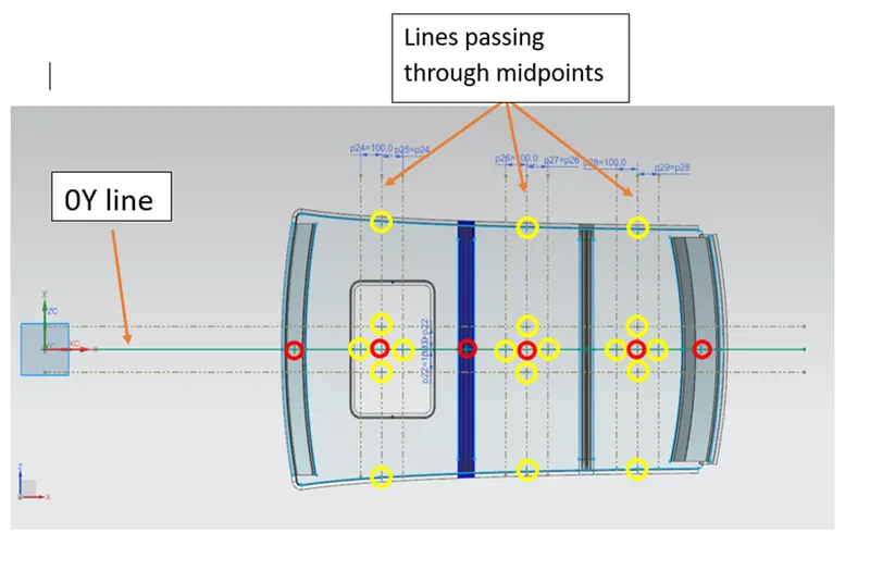
The points in yellow are projected onto the surface for further calculations.
The Rx and Ry are calculated in the same way as for heat distortion criteria by creating arcs.
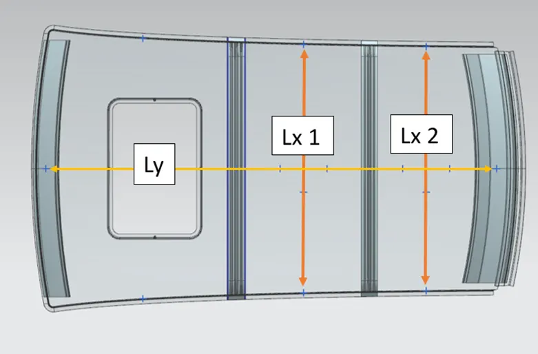
Following picture shows the way of calculating Lx1, Lx2 and ly. Since this design has a sun roof , the calculation between front roof rail and the reinforcement roof is omitted.
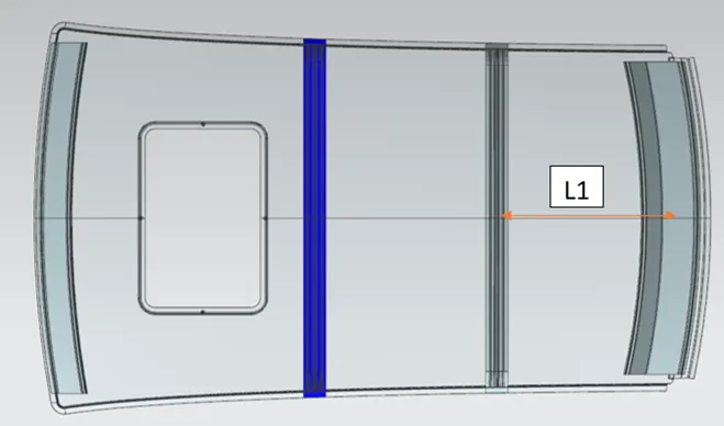
Similarly, L1 and L2 for case1 and case2 are calculated.

For case2, L2 is 0.
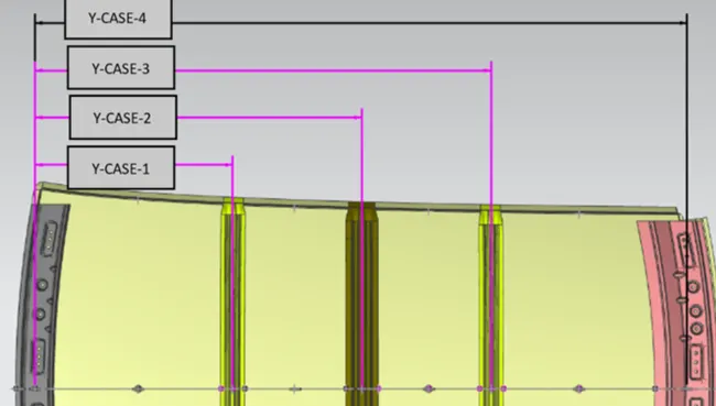
Below is the image for calculating the y distance for each case. In this design only case3 and case 4 from the picture are considered.
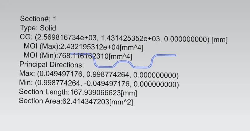
To calculate Iy, at first the cross section of bow roof 2 is taken. Then by projecting it in a sketch, the sectional moment of inertia is calculated using section inertia analysis tool.
Since the value of L2 for second case is 0 it is not considered for calculation.
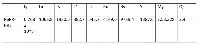
As the Qr value does not satisfy the requirements. Hence, the position of the bow roofs should be adjusted.
Draft Analysis:
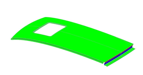
Draft analysis is performed to check whether the part is manufacturable or not. When sheet metal is deep drawn it tends to stick to the surface of the cavity due to expansion. If the cavity doesn’t have a predefined draft angle then ejection of the part becomes difficult and sometimes the die is also damaged. To prevent this a minimum of 7 degrees of draft angle is provide in every area of the sheet metal component. The draft analysis shows draft in each area of the component. The draw direction is the direction in which the core and cavity moves. In this CAD part it is Y axis. Following are the draft analysis results:
1. Roof Outer Panel-
2. Front Roof Rail-
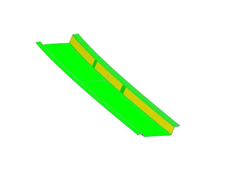
3. raer Roof Rail-
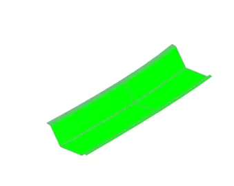
4. Bow Roof 1-
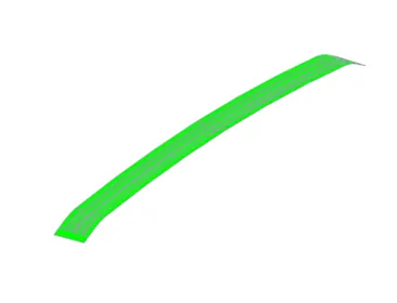
5. Bow Roof 2-
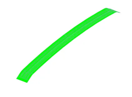
6. Reinforcement Roof Rail -
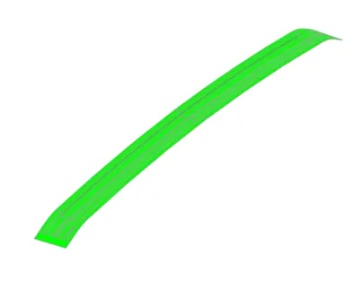
Result
The draft analysis results shows that,
The rear part of the outer panel is showing negative draft. Since, the master section is designed in this way we cannot change it to positive. Hence it is accepted.
The yellow portion in the front roof rail is exact 7 degrees. Hence it is accepted.
All other parts show positive draft angles.
Conclusion
A roof is designed from the given outer panel and master sections. The design included creating roof rails and bow roofs. The positioning of the bow roofs is determined with heat distortion and snow load criterias. The heat distortion criteria passes the calculated value. On the other hand snow load criteria has failed to strengthen the roof portion between reinforcement roof rail and bow roof 2. This can be optimized by changing the positions of the bow roofs. Finally, all the parts are analysed for drafting. All parts show positive drafts. Hence, the car roof is completed.