Creating Column, Drawing Schedule and Drawing Template
Challenges – Week 5
Submitted By Kanala Rahul Reddy
Comands used in this Challenge are
- Line
- Rectangle
- Offset
- Point
- Move
- Circle
- Hatch
- Copy
- Array
- Divide
- Explode
- Leader
- Trim
- Text
- Textedit
- TXT2MTXT
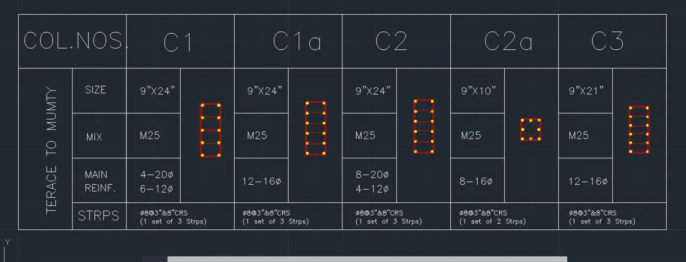
- Create a column schedule as shown in the figure.
Note: Create a column schedule with the help of lines. Also, insert text with the help of Dtext command or Single Line text.
Hint: Use font name: romans.shx; Height: 8”, Justify: Left
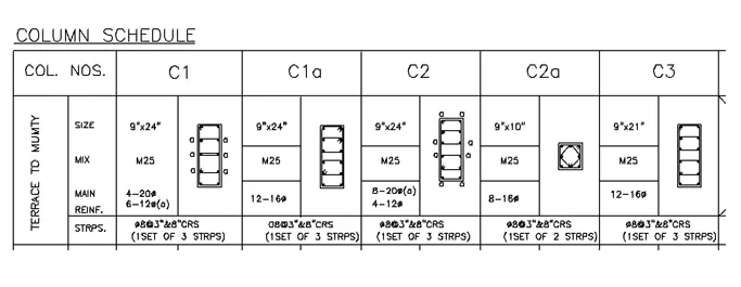
Aim: To create a column schedule as shown in figure
Introduction: The
Procedure:
Open AutoCAD
In Startup settings start from scratch select Imperial (Feet and inches)
Open grid and snap settings
- Change snap and grid spacing to 1’
- Change major line every grid line to 10’
- Turnoff adaptive grid
Type ‘un’ in command box and press enter
- Change units’ type to architectural and precision to 1’1/16”
Step 1: Creating Table using lines
Type line command (Line or L) in the command line and press enter
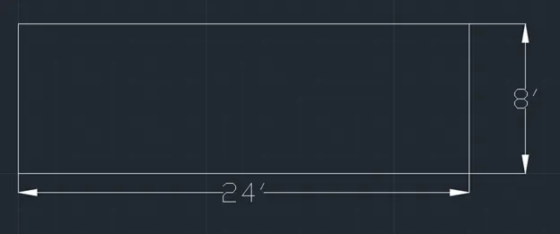
- Specify First Point(undo): Type (10’,10’) and press enter
- Specify Next Point(undo): Type @24’,0 and press enter
- Specify Next Point(undo): Type @0,8’ and press enter
- Specify Next Point(undo): Type @-24’,0 and press enter
- Specify Next Point (undo: Close): press close to complete the figure
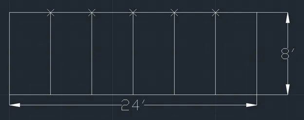
Type ‘div’ or divide in command box and press enter
- Select objects to divide: Select top line of box drawn before
- Enter number of segments: Type 6 and press enter
Type pdmode in command box and press enter
- Enter new value for pdmode <0>: Type 3 and press enter
Type line command (Line or L) in the command line and press enter
- Specify First Point(undo): Turn on OSNAP and orthomode and select the points
- Specify Next Point(undo): Draw a perpendicular line to the bottom line
Type ‘po’ or point in the command box and press enter
- Specify a point: Turn on OSNAP and keep the curser on the top left corner of the outer box and start polar tracking to down and type 2’ and press enter
- Press enter again to start point command again
- Specify a point: Turn on OSNAP and keep the curser on the top left corner of the outer box and start polar tracking to down and type 7’ and press enter
Type line command (Line or L) in the command line and press enter
- Specify First Point(undo): Turn on OSNAP and orthomode and select the points created above
- Specify Next Point(undo): Draw a perpendicular line to the right line
Type ‘div’ or divide in command box and press enter
- Select objects to divide: Select the line drawn 2’ from the top
- Enter number of segments: Type 12 and press enter
Type line command (Line or L) in the command line and press enter
- Specify First Point(undo): Turn on OSNAP and orthomode and select the points created above
- Specify Next Point(undo): Draw a perpendicular line to the bottom line at 7’ from the top line except for the first line
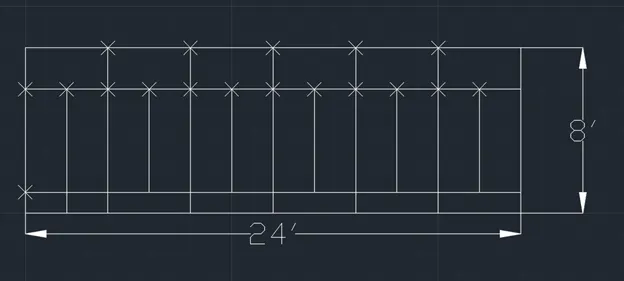
Step 2: Creating Column Sections
C1:
Type ‘rec’ or rectangle in the command box or select rectangle from the draw toolbar
- Specify first corner point: Select any point on the grid
- Specify other corner point or [ Area: Dimension: Rotation]: Click on dimensions
- Specify length for rectangle: Type 9” and press enter
- Specify width for rectangle: Type 24” and press enter and set the direction as first quadrant
Type ‘o’ and press enter or click offset from the modify tool bar
- Specify offset distance: Type 0.5” and press enter
- Select object to offset: Select the rectangle drawn earlier and select the inside of the rectangle
Type ‘C’ or Circle in the command box or select circle from the draw toolbar
- Specify center point for circle [3P: 2P: Ttr (Tan Tan Rad)]: Select Ttr
- Specify point on object for first tangent of circle: Select the left edge of the offset rectangle
- Specify point on object for second tangent of circle: Select the bottom edge of the offset rectangle
- Specify radius of the circle: Type 0.3937(10mm in inches) and press enter
Repeat the same along the other 3 corners
Create a line at 5.553” from the bottom edge of offset rectagle
Type ‘C’ or Circle in the command box or select circle from the draw toolbar
- Specify center point for circle [3P: 2P: Ttr (Tan Tan Rad)]: Select Ttr
- Specify point on object for first tangent of circle: Select the left edge of the offset rectangle
- Specify point on object for second tangent of circle: Select the line created at an offset of 5.553”
- Specify radius of the circle: Type 0.236” (6mm in inches) and press enter
Type ‘C’ or Circle in the command box or select circle from the draw toolbar
- Specify center point for circle [3P: 2P: Ttr (Tan Tan Rad)]: Select Ttr
- Specify point on object for first tangent of circle: Select the right edge of the offset rectangle
- Specify point on object for second tangent of circle: Select the line created at an offset of 5.553”
- Specify radius of the circle: Type 0.236” (6mm in inches) and press enter
Offset the 2 circles drawn earlier at a distance of 5.553”
Type line command (Line or L) in the command line and press enter
- Specify First Point(undo): Turn on OSNAP and orthomode and select the quadrant point of array circles drawn
- Specify Next Point(undo): Draw a straight line towards the opposite circles
Using line command draw the extra bend portions of reinforcement
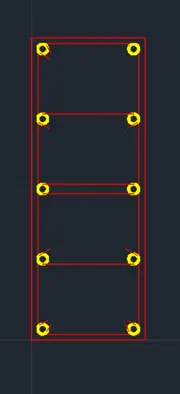
C1a:
Type ‘rec’ or rectangle in the command box or select rectangle from the draw toolbar
- Specify first corner point: Select any point on the grid
- Specify other corner point or [ Area: Dimension: Rotation]: Click on dimensions
- Specify length for rectangle: Type 9” and press enter
- Specify width for rectangle: Type 24” and press enter and set the direction as first quadrant
Type ‘o’ and press enter or click offset from the modify tool bar
- Specify offset distance: Type 0.5” and press enter
- Select object to offset: Select the rectangle drawn earlier and select the inside of the rectangle
Type ‘C’ or Circle in the command box or select circle from the draw toolbar
- Specify center point for circle [3P: 2P: Ttr (Tan Tan Rad)]: Select Ttr
- Specify point on object for first tangent of circle: Select the left edge of the offset rectangle
- Specify point on object for second tangent of circle: Select the bottom edge of the offset rectangle
- Specify radius of the circle: Type 0.314961” (8mm in inches) and press enter
Type ‘C’ or Circle in the command box or select circle from the draw toolbar
- Specify center point for circle [3P: 2P: Ttr (Tan Tan Rad)]: Select Ttr
- Specify point on object for first tangent of circle: Select the right edge of the offset rectangle
- Specify point on object for second tangent of circle: Select the bottom edge of the offset rectangle
- Specify radius of the circle: Type 0.314961” (8mm in inches) and press enter
Type ‘expl’ or explode in the command box and press enter
- Select objects: Select the offset rectangle
Type ‘AR’ or array in command box or select array from the modify tool bar
- Select objects: Select the circle drawn earlier at the left edge and press enter
- Select Array type [Rectangular Path Polar]: Select Path
- Select path curve: Click on left edge of the offset rectangle
- Select the grip to edit array [items]: Click on items
- Specify the distance between items along path: Type 4.4740156” and press enter
Do the same procedure on right side edge of offset rectangle
Type line command (Line or L) in the command line and press enter
- Specify First Point(undo): Turn on OSNAP and orthomode and select the quadrant point of array circles drawn
- Specify Next Point(undo): Draw a straight line towards the opposite circles
Using line command draw the extra bend portions of reinforcement
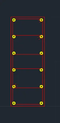
C2:
Type ‘rec’ or rectangle in the command box or select rectangle from the draw toolbar
- Specify first corner point: Select any point on the grid
- Specify other corner point or [ Area: Dimension: Rotation]: Click on dimensions
- Specify length for rectangle: Type 9” and press enter
- Specify width for rectangle: Type 24” and press enter and set the direction as first quadrant
Type ‘o’ and press enter or click offset from the modify tool bar
- Specify offset distance: Type 0.5” and press enter
- Select object to offset: Select the rectangle drawn earlier and select the inside of the rectangle
Type ‘C’ or Circle in the command box or select circle from the draw toolbar
- Specify center point for circle [3P: 2P: Ttr (Tan Tan Rad)]: Select Ttr
- Specify point on object for first tangent of circle: Select the left edge of the offset rectangle
- Specify point on object for second tangent of circle: Select the bottom edge of the offset rectangle
- Specify radius of the circle: Type 0.314961” (8mm in inches) and press enter
Repeat the same along the other 3 corners
Create a line at 8.9480312” from the bottom edge of offset rectangle
Offset the 2 circles drawn earlier at a distance of 4.4740156” to top
Type ‘C’ or Circle in the command box or select circle from the draw toolbar
- Specify center point for circle [3P: 2P: Ttr (Tan Tan Rad)]: Select Ttr
- Specify point on object for first tangent of circle: Select the left edge of the offset rectangle
- Specify point on object for second tangent of circle: Select the bottom edge of the offset rectangle
- Specify radius of the circle: Type 0.3937” (10mm in inches) and press enter
Type ‘C’ or Circle in the command box or select circle from the draw toolbar
- Specify center point for circle [3P: 2P: Ttr (Tan Tan Rad)]: Select Ttr
- Specify point on object for first tangent of circle: Select the right edge of the offset rectangle
- Specify point on object for second tangent of circle: Select the line created at an offset of 4.4740156”
- Specify radius of the circle: Type 0.3937” (10mm in inches) and press enter
Create a line at 4.4740156” from the bottom edge of offset rectangle
Type ‘C’ or Circle in the command box or select circle from the draw toolbar
- Specify center point for circle [3P: 2P: Ttr (Tan Tan Rad)]: Select Ttr
- Specify point on object for first tangent of circle: Select the left edge of the offset rectangle
- Specify point on object for second tangent of circle: Select the line created at an offset of 4.4740156”
- Specify radius of the circle: Type 0.236” (6mm in inches) and press enter
Type ‘C’ or Circle in the command box or select circle from the draw toolbar
- Specify center point for circle [3P: 2P: Ttr (Tan Tan Rad)]: Select Ttr
- Specify point on object for first tangent of circle: Select the right edge of the offset rectangle
- Specify point on object for second tangent of circle: Select the line created at an offset of 4.4740156”
- Specify radius of the circle: Type 0.236” (6mm in inches) and press enter
Type line command (Line or L) in the command line and press enter
- Specify First Point(undo): Turn on OSNAP and orthomode and select the quadrant point of array circles drawn
- Specify Next Point(undo): Draw a straight line towards the opposite circles
Using line command draw the extra bend portions of reinforcement as follows
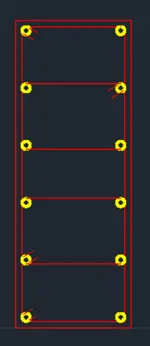
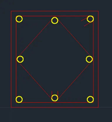
C2a:
Type ‘rec’ or rectangle in the command box or select rectangle from the draw toolbar
- Specify first corner point: Select any point on the grid
- Specify other corner point or [ Area: Dimension: Rotation]: Click on dimensions
- Specify length for rectangle: Type 9” and press enter
- Specify width for rectangle: Type 10” and press enter and set the direction as first quadrant
Type ‘o’ and press enter or click offset from the modify tool bar
- Specify offset distance: Type 0.5” and press enter
- Select object to offset: Select the rectangle drawn earlier and select the inside of the rectangle
Type ‘C’ or Circle in the command box or select circle from the draw toolbar
- Specify center point for circle [3P: 2P: Ttr (Tan Tan Rad)]: Select Ttr
- Specify point on object for first tangent of circle: Select the left edge of the offset rectangle
- Specify point on object for second tangent of circle: Select the bottom edge of the offset rectangle
- Specify radius of the circle: Type 0.314961” (8mm in inches) and press enter
Apply same procedure to all the corners
Draw a rhombus joining all the mid points of the offset rectangle edges
Type ‘C’ or Circle in the command box or select circle from the draw toolbar
- Specify center point for circle [3P: 2P: Ttr (Tan Tan Rad)]: Select Ttr
- Specify point on object for first tangent of circle: Select the inclined edge of the rhombus draw
- Specify point on object for second tangent of circle: Select the next inclined edge of the rhombus draw
- Specify radius of the circle: Type 0.314961” (8mm in inches) and press enter
Apply same procedure at all the corners of rhombus
Using line command draw the extra bend portions of reinforcement
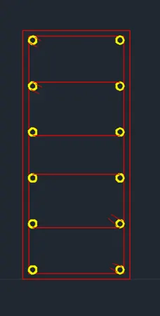
C3:
Type ‘rec’ or rectangle in the command box or select rectangle from the draw toolbar
- Specify first corner point: Select any point on the grid
- Specify other corner point or [ Area: Dimension: Rotation]: Click on dimensions
- Specify length for rectangle: Type 9” and press enter
- Specify width for rectangle: Type 21” and press enter and set the direction as first quadrant
Type ‘o’ and press enter or click offset from the modify tool bar
- Specify offset distance: Type 0.5” and press enter
- Select object to offset: Select the rectangle drawn earlier and select the inside of the rectangle
Type ‘C’ or Circle in the command box or select circle from the draw toolbar
- Specify center point for circle [3P: 2P: Ttr (Tan Tan Rad)]: Select Ttr
- Specify point on object for first tangent of circle: Select the left edge of the offset rectangle
- Specify point on object for second tangent of circle: Select the bottom edge of the offset rectangle
- Specify radius of the circle: Type 0.314961” (8mm in inches) and press enter
Type ‘C’ or Circle in the command box or select circle from the draw toolbar
- Specify center point for circle [3P: 2P: Ttr (Tan Tan Rad)]: Select Ttr
- Specify point on object for first tangent of circle: Select the right edge of the offset rectangle
- Specify point on object for second tangent of circle: Select the bottom edge of the offset rectangle
- Specify radius of the circle: Type 0.314961” (8mm in inches) and press enter
Type ‘expl’ or explode in the command box and press enter
- Select objects: Select the offset rectangle
Type ‘AR’ or array in command box or select array from the modify tool bar
- Select objects: Select the circle drawn earlier at the left edge and press enter
- Select Array type [Rectangular Path Polar]: Select Path
- Select path curve: Click on left edge of the offset rectangle
- Select the grip to edit array [items]: Click on items
- Specify the distance between items along path: Type 3.8740” and press enter
Do the same procedure on right side edge of offset rectangle
Type line command (Line or L) in the command line and press enter
- Specify First Point(undo): Turn on OSNAP and orthomode and select the quadrant point of array circles drawn
- Specify Next Point(undo): Draw a straight line towards the opposite circles
Using line command draw the extra bend portions of reinforcement
Step 3: Writing Text
Go to annotate tab and click on the arrow at the below to open the text properties
In the dialogue box click on new style
- Set style name to ‘New’
- Change Font Name to romans.shx
- Change height to 8”
- Click on set current and apply and close
Type ‘text’ in command box and press enter
- Specify start point of the text: Select inside the first box at the start point
- Specify rotation angle of text: Type 0o press enter
- Now the type the Col. And Nos. in the line and press esc
Follow the same procedure to all the horizontal text
Type ‘text’ in command box and press enter
- Specify start point of the text: Select inside the first box at the start point
- Specify rotation angle of text: Type 90o press enter
- Now the type the TERACE TO MUMTY in the line and press esc
For longer text create a multiline text
Step 4: Moving column objects
Type ‘m’ or move in command box and press enter or select move from the modify tool bar
- Select objects to move: Select the column drawn respectively
- Specify base point: Select the bottom left point of the column
- Specify second point of placement: Select the respective column of the table and place it in the middle
Follow the same procedure for all the columns
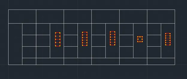
Result:
The final end result of above steps is as follows
The text is justified to the left
The text style used is romans.shx and text height is 8”
Notes:
- All dimensions are in feet and inches
- Columns- Red
- Main Reinforcement- Yellow
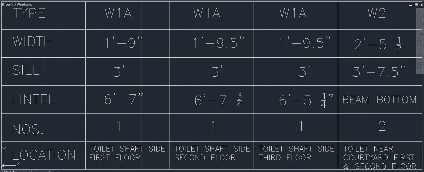
- Create a window schedule as shown in the figures:
Window Schedule:
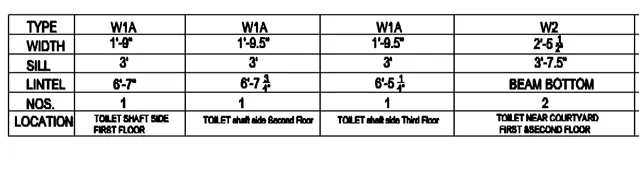
Aim: To create a window schedule as shown in figure
Introduction: The
Procedure:
Open AutoCAD
In Startup settings start from scratch select Imperial (Feet and inches)
Open grid and snap settings
- Change snap and grid spacing to 1’
- Change major line every grid line to 10’
- Turnoff adaptive grid
Type ‘un’ in command box and press enter
- Change units’ type to architectural and precision to 1’1/16”
Step 1: Creating Table using lines
Type line command (Line or L) in the command line and press enter
- Specify First Point(undo): Type (10’,10’) and press enter
- Specify Next Point(undo): Type @30’,0 and press enter
- Specify Next Point(undo): Type @0,10’ and press enter
- Specify Next Point(undo): Type @-20’,0 and press enter
- Specify Next Point (undo: Close): press close to complete the figure
Type ‘div’ or divide in command box and press enter
- Select objects to divide: Select top line of box drawn before
- Enter number of segments: Type 5 and press enter
Type ‘div’ or divide in command box and press enter
- Select objects to divide: Select left line of box drawn before
- Enter number of segments: Type 6 and press enter
Type pdmode in command box and press enter
- Enter new value for pdmode <0>: Type 3 and press enter
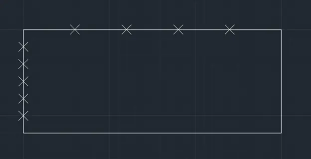
Type line command (Line or L) in the command line and press enter
- Specify First Point(undo): Turn on OSNAP and orthomode and select the points
- Specify Next Point(undo): Draw a perpendicular line to the bottom line
Create line at all point to opposite side perpendicular along with horizontal lines
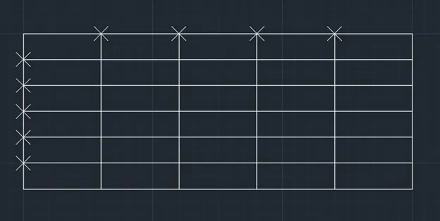
Type pdmode in command box and press enter
- Enter new value for pdmode <3>: Type 0 and press enter
Step 2: Writing Text
Go to annotate tab and click on the arrow at the below to open the text properties
In the dialogue box click on new style
- Set style name to ‘New’
- Change Font Name to romans.shx
- Change height to 8”
- Click on set current and apply and close
Type ‘text’ in command box and press enter
- Specify start point of the text: Select inside the first box at the start point
- Specify rotation angle of text: Type 0o press enter
- Now the type the TYPE in the line and press esc
Follow the same procedure to all the horizontal text
For longer text create a multiline text
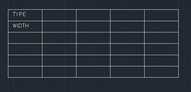
Result:
The final end result of above steps is as follows
The text is justified to the left
The text style used is romans.shx and text height is 8”
Notes:
- All dimensions are in feet and inches
3. Create the drawing template as shown in the figure:< Use the Notes as in the figure>
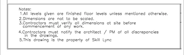

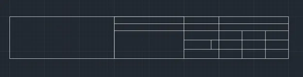
Aim: To create above text and table in AutoCAD
Procedure:
Open AutoCAD
In Startup settings start from scratch select Imperial (Feet and inches)
Open grid and snap settings
- Change snap and grid spacing to 1’
- Change major line every grid line to 10’
- Turnoff adaptive grid
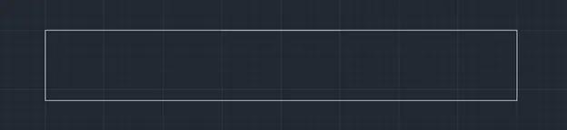
Step 1: Creating Table using lines
Type line command (Line or L) in the command line and press enter
- Specify First Point(undo): Type (10’,10’) and press enter
- Specify Next Point(undo): Type @80’,0 and press enter
- Specify Next Point(undo): Type @0,10’ and press enter
- Specify Next Point(undo): Type @-80’,0 and press enter
- Specify Next Point (undo: Close): press close to complete the figure
Type pdmode in command box and press enter
- Enter new value for pdmode <0>: Type 3 and press enter
Type ‘po’ or point in command box and press enter
- Specify point: Keep the curser on the top left end and start polar tracking to right and type 30’ and press enter
- Press enter to reactivate point command
- Specify point: Keep the curser on the top left end and start polar tracking to right and type 50’ and press enter
Type line command (Line or L) in the command line and press enter
- Specify First Point(undo): Turn on OSNAP and orthomode and select the points
- Specify Next Point(undo): Draw a perpendicular line to the bottom line
Create line at all point to opposite side perpendicular along with horizontal lines
Create off set lines of top edge of box at 2’ each and trim off the unwanted parts
Type ‘o’ and press enter or click offset from the modify tool bar
- Specify offset distance: Type 2.667’ and press enter
- Select object to offset: Select the third box left edge and click on the right side of the line
Trim of extra potions
Type pdmode in command box and press enter
- Enter new value for pdmode <3>: Type 0 and press enter
Step 2: Writing Text
Go to annotate tab and click on the arrow at the below to open the text properties
In the dialogue box click on new style
- Set style name to ‘New’
- Change Font Name to romans.shx
- Change height to 8”
- Click on set current and apply and close
Type ‘text’ in command box and press enter
- Specify start point of the text: Select inside the first box at the start point
- Specify rotation angle of text: Type 0o press enter
- Now the type the Project: Pear; Villa in the line and press esc
Follow the same procedure to all the horizontal text
For Notes create a multiline text

Result:
The final end result of above steps is as follows
The text is justified to the left
The text style used is romans.shx and text height is 8”
Notes:
- All dimensions are in feet and inches

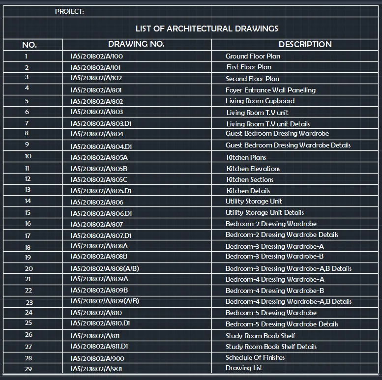
- Create the list of drawing schedule as shown in the figure:
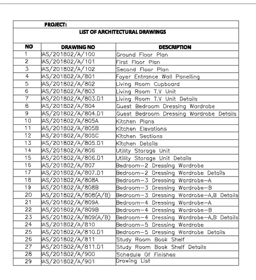
Aim: To create above text and table in AutoCAD
Procedure:
Open AutoCAD
In Startup settings start from scratch select Imperial (Feet and inches)
Open grid and snap settings
- Change snap and grid spacing to 1’
- Change major line every grid line to 10’
- Turnoff adaptive grid
Step 1: Creating Table using lines
Type line command (Line or L) in the command line and press enter
- Specify First Point(undo): Type (10’,10’) and press enter
- Specify Next Point(undo): Type @60’,0 and press enter
- Specify Next Point(undo): Type @0,49’6”’ and press enter
- Specify Next Point(undo): Type @-60’,0 and press enter
- Specify Next Point (undo: Close): press close to complete the figure
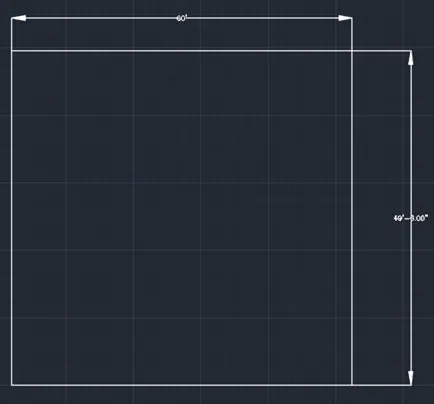
Type pdmode in command box and press enter
- Enter new value for pdmode <0>: Type 3 and press enter
Type ‘po’ or point in command box and press enter
- Specify point: Keep the curser on the top left end and start polar tracking to right and type 10’ and press enter
- Press enter to reactivate point command
- Specify point: Keep the curser on the top left end and start polar tracking to right and type 30’ and press enter
Type line command (Line or L) in the command line and press enter
- Specify First Point(undo): Turn on OSNAP and orthomode and select the points
- Specify Next Point(undo): Draw a perpendicular line to the bottom line
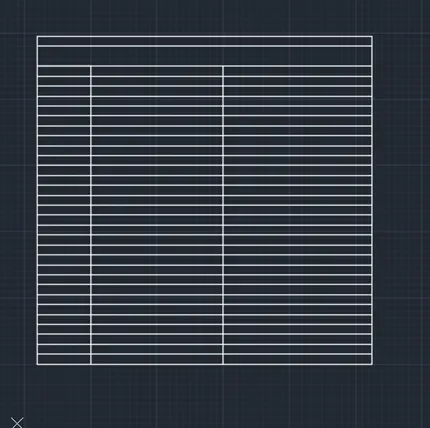
Create line at all point to opposite side perpendicular along with horizontal lines
Type ‘o’ and press enter or click offset from the modify tool bar
- Specify offset distance: Type 1.5’ and press enter
- Select object to offset: Select the top edge of the box and click on the down side of the line
- Press enter twice
- Specify offset distance: Type 3’ and press enter
- Select object to offset: Select the last offset line and click on the down side of the line
- Press enter twice
- Specify offset distance: Type 1.5’ and press enter
- Select object to offset: Select the last offset line and click on the down side of the line
Repeat the same procedure until the reaching bottom edge
Trim of extra potions
Type pdmode in command box and press enter
- Enter new value for pdmode <3>: Type 0 and press enter
Step 2: Writing Text
Go to annotate tab and click on the arrow at the below to open the text properties
In the dialogue box click on new style
- Set style name to ‘New’
- Change Font Name to Berlin sans FB
- Change height to 8”
- Click on set current and apply and close
Type ‘text’ in command box and press enter
- Specify start point of the text: Select inside the first box at the start point
- Specify rotation angle of text: Type 0o press enter
- Now the type the Project: in the line and press esc
Follow the same procedure to all the horizontal text
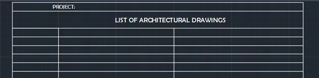
Result:
The final end result of above steps is as follows
The text is justified to the left
- The text style used is Berlin sans FB and text height is 8”
Notes:
- All dimensions are in feet and inches
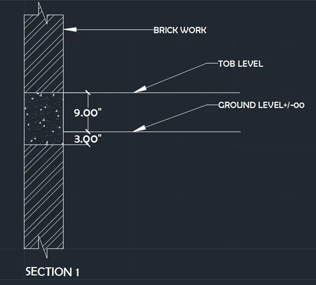
- Create the Beam detail as shown in the figure and provide text for Top level and Ground level wherever given.
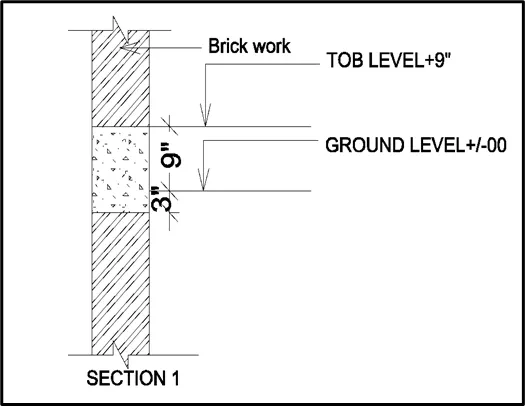
Aim: To Create the Beam detail as shown in the figure
Procedure:
Open AutoCAD
In Startup settings start from scratch select Imperial (Feet and inches)
Open grid and snap settings
- Change snap and grid spacing to 1’
- Change major line every grid line to 10’
- Turnoff adaptive grid
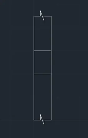
Step 1: Creating Section view of beam
Type ‘rec’ or rectangle in the command box or select rectangle from the draw toolbar
- Specify first corner point: Type 10’,10’ and press enter
- Specify other corner point or [ Area: Dimension: Rotation]: Click on dimensions
- Specify length for rectangle: Type 9” and press enter
- Specify width for rectangle: Type 4.5’ and press enter and set the direction as first quadrant
Type ‘expl’ or explode in the command box and press enter
- Select objects: Select the rectangle
Type ‘o’ and press enter or click offset from the modify tool bar
- Specify offset distance: Type 2’ and press enter
- Select object to offset: Select the bottom edge rectangle drawn earlier and select the inside of the rectangle
- Press enter to reactivate the offset command
- Specify offset distance: Type 1’ and press enter
- Select object to offset: Select the offset line drawn and select the upside of the line
Create cross-section symbol as shown in the picture and delete the previous lines
Step 2: Adding Hatch Portions
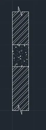
Type ‘h’ or hatch in the command box and press enter or select hatch command from the draw tool bar
- Select the hatch pattern AR-CONCRETE
- Pick an internal point: Pick a point in the center box formed
- Press enter twice to reactivate the hatch command
- Select the hatch pattern ANS132
- Pick an internal point: Pick a point in the top and bottom box and press enter
Step 2: Writing Text
Go to annotate tab and click on the arrow at the below to open the text properties
In the dialogue box click on new style
- Set style name to ‘New’
- Change Font Name to Berlin sans FB
- Change height to 1.5”
- Click on set current and apply and close
Type ‘text’ in command box and press enter
- Specify start point of the text: Select inside the first box at the start point
- Specify rotation angle of text: Type 0o press enter
- Now the type the Section 1 in the line and press esc
- From annotation tool bar select the leader text option and click on first level line drawn at a distance from the edge and type text as TOB LEVEL and press enter (Set arrow height as 3”)
- From annotation tool bar select the leader text option and click on second level line drawn at a distance from the edge and type text as GROUND LEVEL +/-00 and press enter (Set arrow height as 3”)
Follow the same procedure to all the horizontal text
Result:
The final end result of above steps is as follows
The text is justified to the left
The text style used is Berlin sans FB and text height is 1.5”
Notes:
- All dimensions are in feet and inches