Reinforcement detailing of Columns from ETABS output
Reinforcement Detailing of Columns from ETABS output.
The ETABS file for a G+4 building is provided. Run the analysis and design the RCC Moment Resisting Frame. The following challenge deals specifically with two columns at the following grid intersections.
- 3A
- 3B
- Provide details of longitudinal reinforcement for the two columns, from foundation to terrace level. Sketch the column cross sectional & elevation details or draft it using autocad software.
- Show shear reinforcement & lapping details as per special confining reinforcement provision of clause 8.1 of IS 13920 - 2016.
Aim:
- To Providing details of longitudinal reinforcement for the two columns from foundation to Terrace level.
Introduction:
Column reinforcement according to IS: 13920 code book clause 7
Longitudinal Reinforcement:
- Minimum dimension of a column shall not be less than 20db largest diameter of longitudinal reinforcement bar in the beam which is passing through column and 300mm.
- Aspect ratio i.e., B / D should not be less than 0.45
- In lap splices
- Spacing of link shall not exceed 100mm.
- Lap splices should not be less than development length of largest reinforcement bar.
- Lap splices shall be provided at center of column height, not within joint or not within a distance of 2d from joint.
- Not more than 50% of area of steel bars shall be spliced at any one section.
- Lap splices shall not be used for bars of diameter more than 32mm.
Procedure:
Step: -1
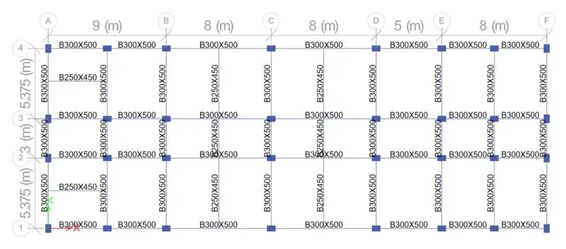
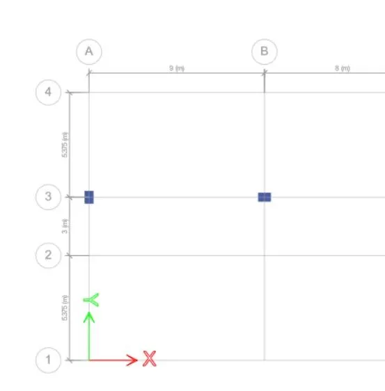
- Open a G+4 Etabs file.
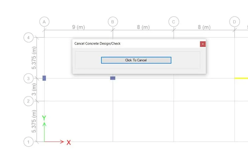
- Click the concrete frame design tool.
- Select the display design info option.
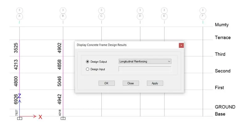
- Choose design output as longitudinal reinforcement.
Step: -2
- After, selecting the longitudinal reinforcement click elevation view.
- To avoid the confusions, click tick mark on ribbon and uncheck. Beam.
Step: -3
- Now need to calculate the reinforcement details of 3A & 3B.
Step: -4
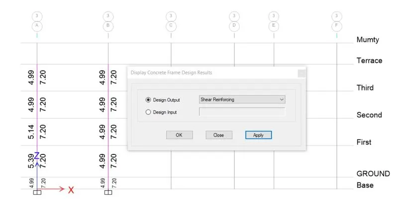
- For shear reinforcement, click the concrete frame design tool.
- Choose shear reinforcing.
- Click apply & OK.
Step: -5
After selecting the shear reinforcement option, the shear reinforcement values are obtained at each column.
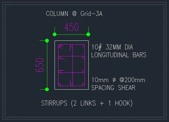
Longitudinal Reinforcement & Shear Reinforcement of Column at Grid-3A from Etabs (450x650):
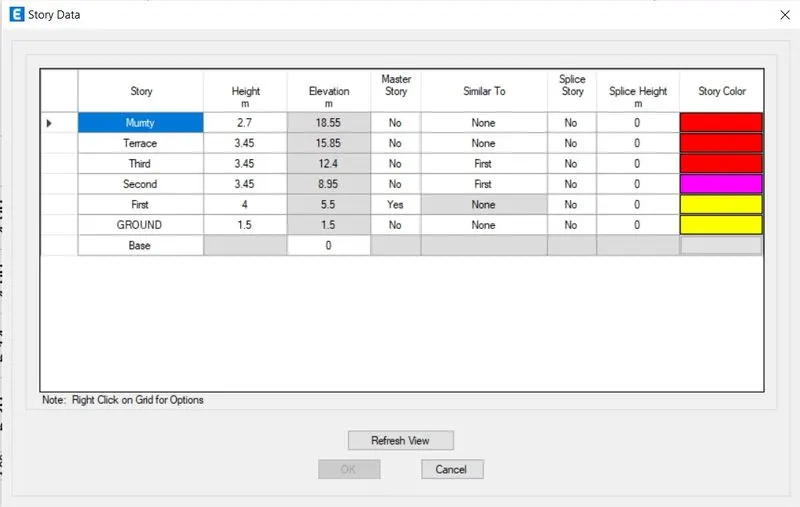
Storey Assignment tab to refer elevation of column.
Step: -6
Note:
- Minimum Longitudinal Reinforcement as per IS-456-2000 clause 26.5.3.1 As = 2340 mm2.
- Minimum Shear Reinforcement as per IS-13920-2016 clause 7.4.2- 8mm dia @ 300mm c/c
GRID A:
Calculation for Longitudinal Reinforcement:
- From base to first floor the maximum Ast is = 6926 mm²
= 6926 / 10 = 692 mm²
= Considering 32 mm dia = Ast = 804 mm²
- So, we can provide 10# of 32 mm dia Longitudinal bar= 10 x 804 = 8040 mm²
Calculation for Shear Reinforcement:
- From base to first floor the maximum shear value is = 720 mm²
=(1000/Sv) X L x Ast
= 1000/200 x 2 x 78.55
=785.5 mm²
- So, we can provide 10mm dia @200 mm spacing shear.
GRID B:
Calculation for Longitudinal Reinforcement:
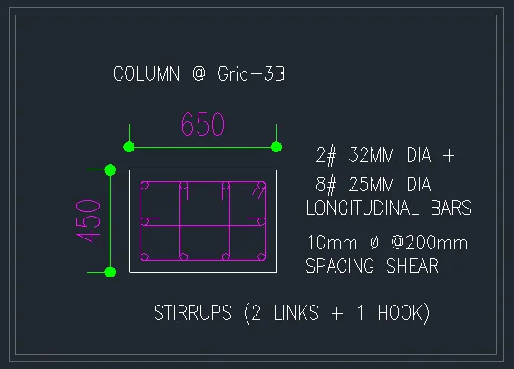
- From base to first floor the maximum Ast is = 5046 mm²
= 5046 / 8 = 630.75 mm²
= Considering 32 mm dia = Ast = 804 mm²
- So, we can provide 8#32 mm dia Longitudinal bar = 8 x 804 =6432 mm²
Calculation for Shear Reinforcement:
- From base to first floor the maximum shear value is = 720 mm²
=(1000/Sv) X L x Ast
= 1000/200 x 2 x 78.55
=785.5 mm²
- So, we can provide 10mm dia @200 mm spacing shear.
Therefore, it can be satisfied the entire span.
Step: -7
Elevation & Cross sectional details of Column using AutoCAD:
Beam Elevation @ Grid-3A Beam Elevation @ Grid-3B
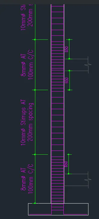
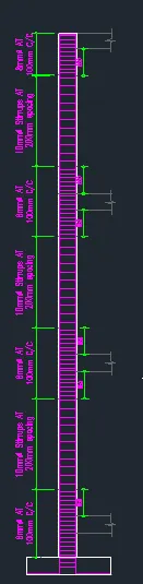
Beam cross section @ Grid-3A Beam cross section @ Grid-3B
RESULT.
- The Columns are designed successfully in detail from the ETABS software.
- Provided the details of longitudinal reinforcement for the two columns (3A & 3B) successfully.
- And calculated the value of Maximum Ast in columns using the ETABS.
- And also provided the column cross sectional & Elevation details using the AutoCAD software.