Reinforcement detailing of Columns from ETABS output
Aim - To provide the details of longitudinal reinforcement for the two columns (3A & 3B), from foundation to terrace level
Introduction -
- A column in architecture and structural engineering is a structural element that transmits, through compression, the weight of the structure above to other structural elements below. In other words, a column is a compression member.
- For the purpose of wind or earthquake engineering, columns may be designed to resist lateral forces.
- The factored axial compression stress considered all load combination relating to sesimic loads shall be limited to 0.40 fck in all column.
- The Minimum Column Dimension as per IS 13290-2016 = 20 db
where db = Max beam bar diameter
- In column cracking will be much less as compared to beam because large amount of axial force is present
Procedure -
Step 1)
i) Open the Challenge 7 Etabs file which we have downloaded for Beam Design
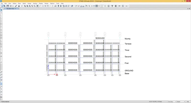
Step 2)
i) Change the Elevation view - 3
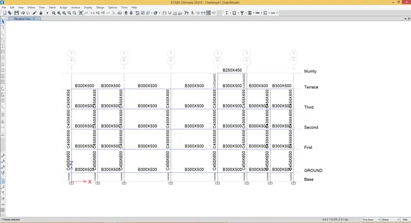
Step 3)
i) Now Click on Run Ananlysis
ii) And Click on Concrete Frame Design
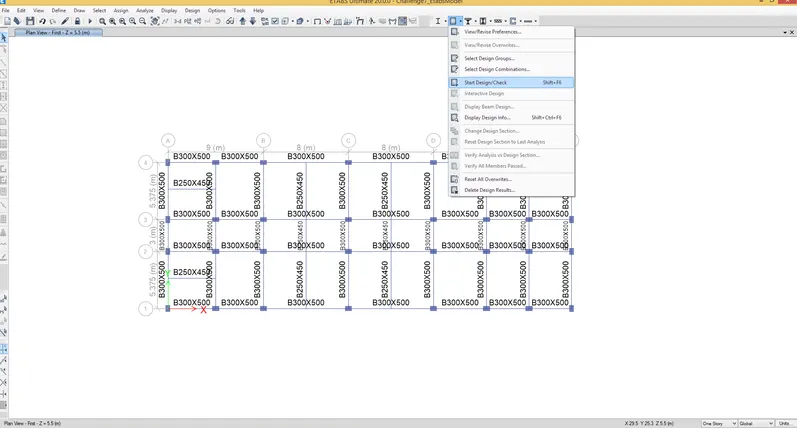
iii) Click on Start Design Check
iv) Wait for completing the process
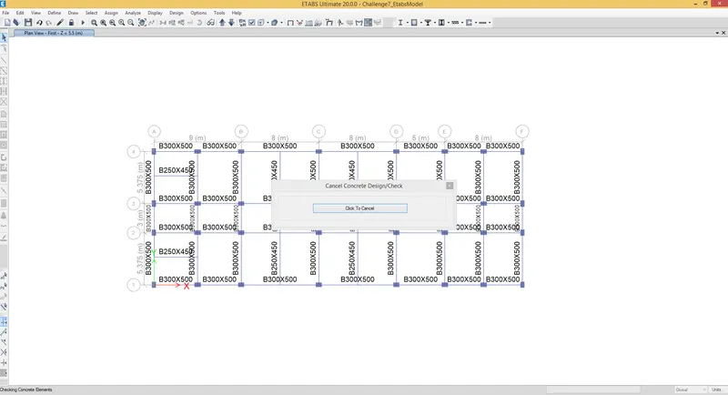
Step 4)
i) Once the design in completed
ii) Now we have the see the detailed reinforcement
iii) For that Click on Start Design Check - Display Design Info
iv) Select Display Output - Longitudinal Reinforcemet
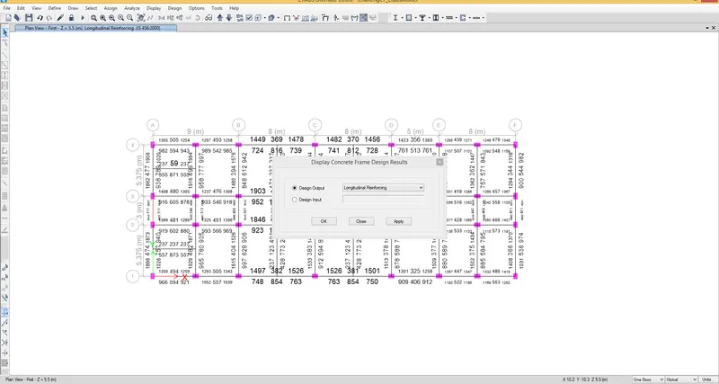
v) Click on Apply and then Okay
Longitudinal Reinforcement
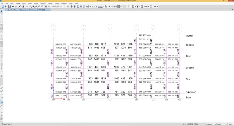
Step 5)
i) Similarly Select the Shear Reinforcement
ii) Display Output - Shear Reinforcement
Shear Reinforcement -
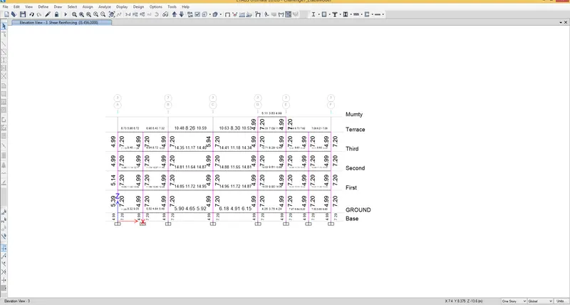
Step 6)
i) Now we have to provide detail reinforcement for Column
1) For GRID 3A -
1) From Base to Terrace floor the maximum Ast is = 7027
2) So we can provide 12nos of 28mm dia bar = 12 x 616
= 7392mm^2
2) For GRID 3B -
1) From Base to Terrace floor the maximum Ast = 5046 mm^2
2) So , Provide 8 bars of 25 mm diameter for the column = 8 x 490.87*8
= 3927mm^2
3) Provide 4 bars of 20 mm diameter for the column = 4 x 314.16
= 1256.64mm^2
4) Total = 3927 + 1257
= 5180 mm^2
Step 7)
Beam column Joint as per special confining reinforcement provision of clause 8.1 of IS 13920 - 2016 i) As per IS 13920 - 2016 at beam column junction -
For beam - The spacing from the face of the beam should not be more than 100 mm till 2d
For Column - The spacing from the face of the column will be lo and should not be more than
= Least lateral dimension
= 1/6)th of clear span
= 450 mm
Result -
i) The detailing of reinforcement column can't done, because i was using Autocad trail version which is now expired.
ii) Shear reinforcement & lapping details as per special confining reinforcement provision
of clause 8.1 of IS 13920 - 2016.
1) For Io - Not Less Than
i) Larger Column Dimension - 650mm
ii) 1/6 )^(th`) of clear span of column - 560mm
iii) 450 mm
So Adopt 650 mm
2) Confinement Spacing Not more than
i) 1/4 th of smaller column dimension = 113 mm
ii) 6 times of dia of column main bar - 168 mm
iii) 100 mm
So we have to adopt 100 mm