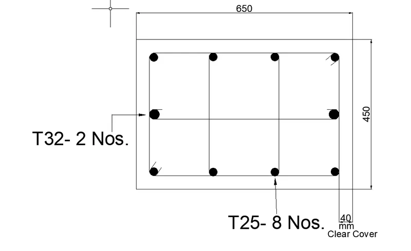
Reinforcement detailing of Columns from ETABS output
Reinforcement detailing of columns in ETABS 2018.
The ETABS file for a G+4 building is provided. Run the analysis and design the RCC Moment Resisting Frame. The following challenge deals specifically with two columns at the following grid intersections.
- 3A
- 3B
- Provide details of longitudinal reinforcement for the two columns, from foundation to terrace level. Sketch the column cross sectional & elevation details or draft it using AutoCAD software.
- Show shear reinforcement & lapping details as per special confining reinforcement provision of clause 8.1 of IS 13920 - 2016.
AIM: - The aim of this challenge is to do the reinforcement detailing of the columns in the ETABS software. To analyse and design the RCC Moment Resisting Frame for the G+4 building which is provided to us in the previous challenge.
- And to provide the details of the longitudinal reinforcement for the two columns i.e., from the foundation to the terrace level.
- And to show the shear reinforcement and the lapping details as per the clause 8.1 of IS 13920-2016.
INTRODUCTION: -
Detailing Rules:
- So below are the given some detailing rules which is provided in the IS code 13920:2016.
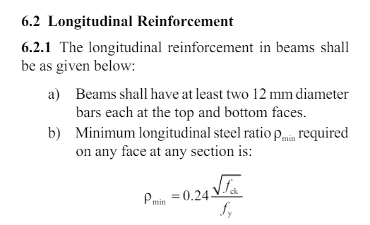
- So according to the IS 13920:2016 clause 6.2.1, the minimum longitudinal reinforcement should be As = 360 sq.mm.
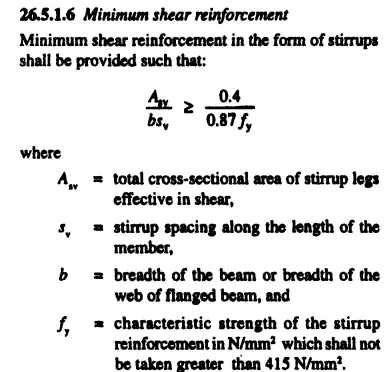
- So according to the IS 456:2000 clause 26.5.1.6, the minimum shear reinforcement should be Asv = 332 sq mm.
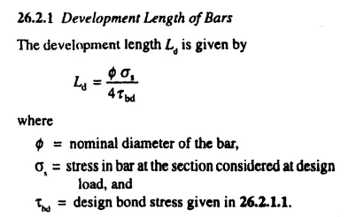
- And the development length as per the IS code 456:2000, clause 26.2.1, Ld= 41XDiameter of the bar just as shown in the below given image:
And among the below 4 conditions we will be going to consider whichever has the greater value:
- Minimum requirement for the shrinkage and the temperature.
- Reinforcement requirement for limiting crack width.
- Ultimate limit state design rebar requirement.
- Ductility rebar requirement.
PROCEDURE: -
- First of all, open the ETABS software.
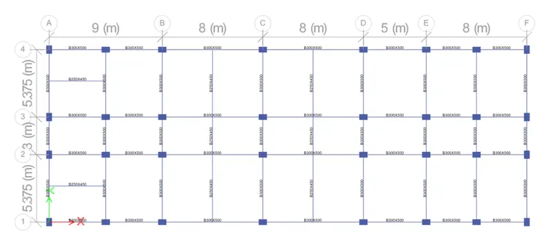
- Then go the File tab from there go to the open option and then open the previous file for the analysis of the column of the G+4 building which we used for 7th week challenge.
- Now the file on which we want to run the analysis is open just as shown in the below image:
- Now after opening the file the very first thing which we need to do is Run Analysis.
- So, in order to do the run analysis first of all go to the Analyse tab at the top of the screen and then at the drop-down list there is an option called Run analysis just as shown in the below given image:
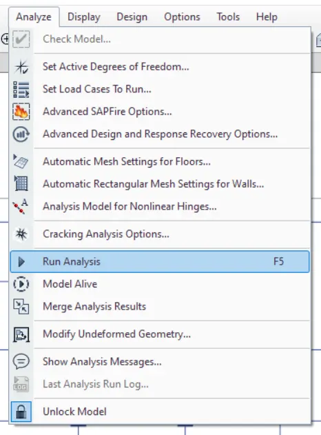
- Or else we can also press F5 or there is another option at the top of the screen to perform the Run analysis. We can choose any option.
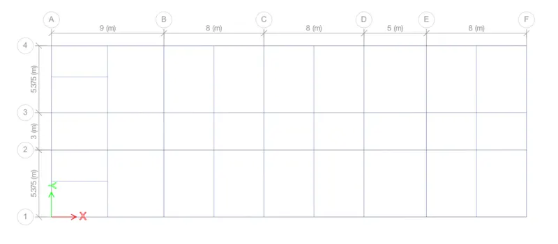
- So now that the Run Analysis have been done here just as shown in the below given image:
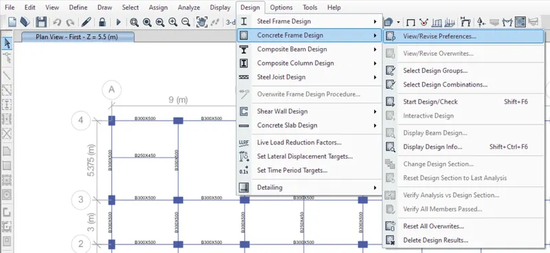
- After doing the Run Analysis next, we have to go to the Design toolbar after clicking on the option Design there is a drop-down list of different options and from that option just click on the option Concrete Frame Design and then click on another option called View/Revise Preferences just as shown in the below given image:
- So, after clicking on the option View/Revise Preferences there is a new dialogue box named as Concrete Frame Design Preferences for IS 456:2000 just as shown in the below figure:
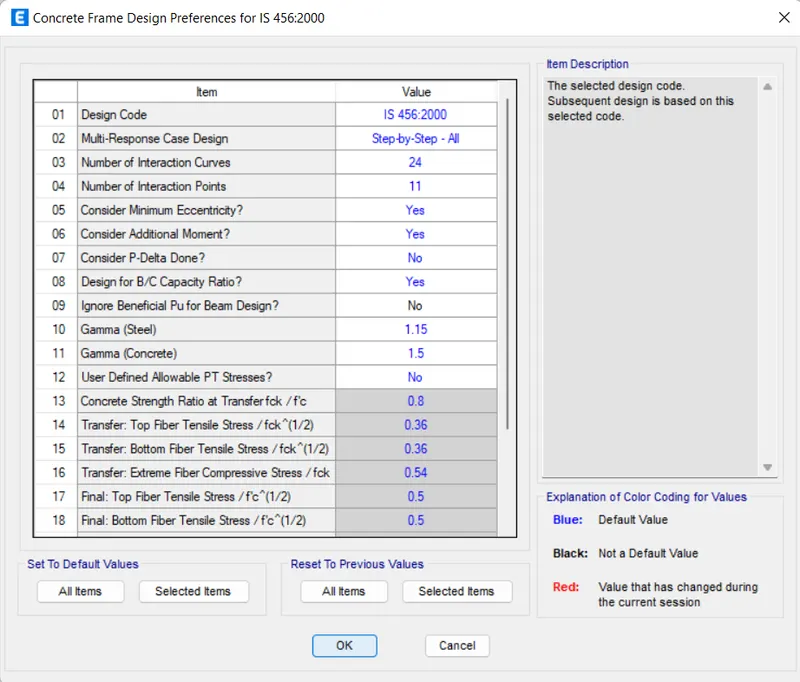
- After confirming the code standards, we need to choose the 2 columns which we are going to analyse and design.
- Now select the column which we are going to analyse and do the detailing process change the view setting to only the selected columns.
- For this just right click on there will be a drop-down list of different options from that list choose the option Show Selected Objects Only just as shown in the below given image:
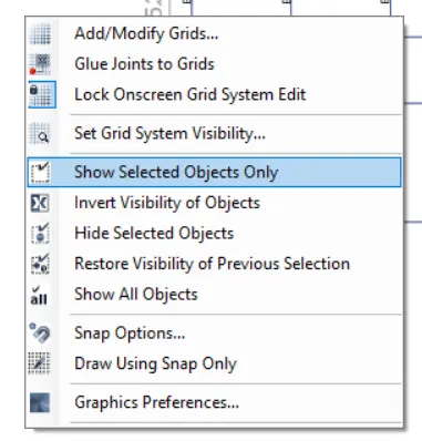
- So below are the selected columns that are selected:
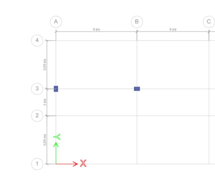
- And below is the image of the 3D view of the selected column:
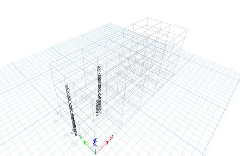
- Now do the run analysis and below is the result after completing the analysis:
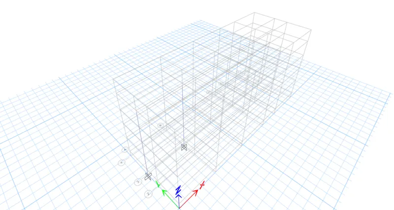
- The maximum and the minimum deflection range is visible at the bottom of the screen just as shown in the below given image:

- After this just press the Concrete Frame Design icon which is available at the top-right side of the screen just as shown in the below given image:
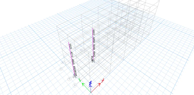
- So, the longitudinal reinforcement results are given below in the image:
- After this just go to the Elevation view along the grid A.
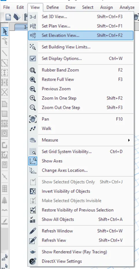
- So, in order to view the elevation view just press the Elevation button present at the top-middle of the screen or just go to the View option then there will be a drop-down list from that list just choose the option Set Elevation View or just press Shift+Control+F2 any method will work just as shown in the below image:
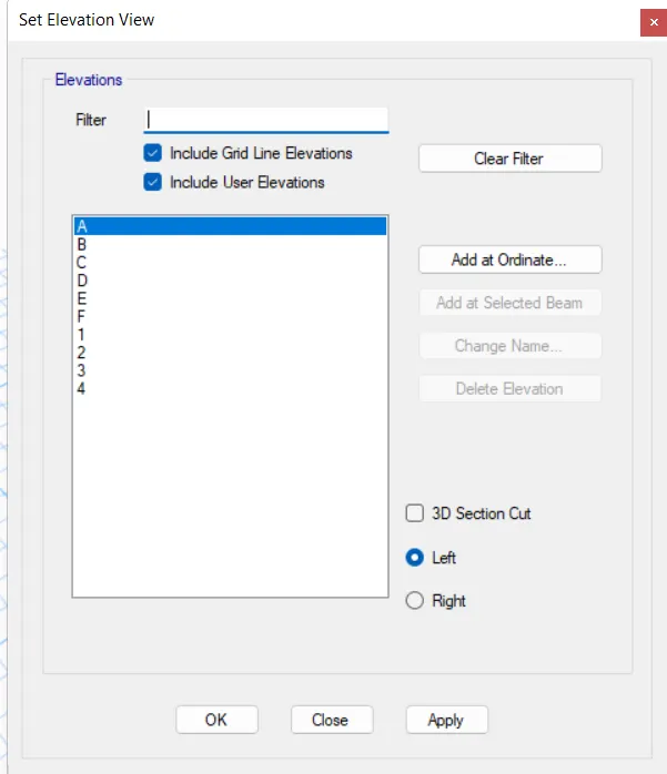
- Now after clicking the elevation view option there will be another dialogue box named as Set Elevation View. From that dialogue box choose the elevation view A just as shown in the below given image:
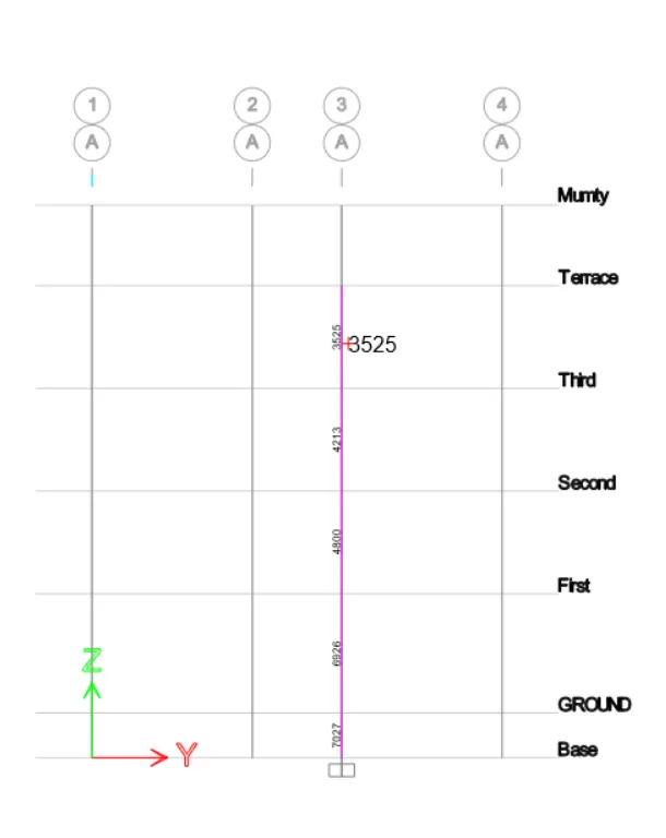
- And below are the column results along grid A:
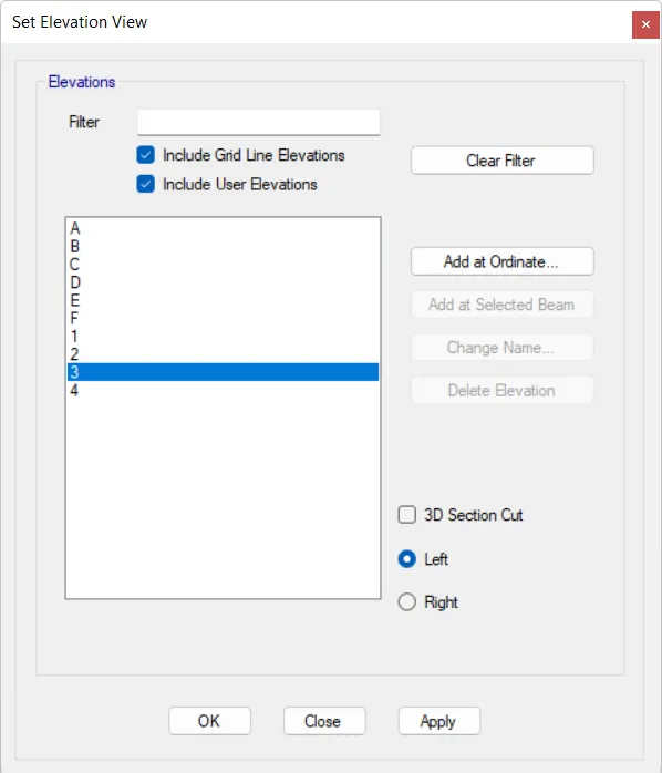
- And now if we want to check this for the grid 3 then from that dialogue box choose the elevation view as 3 just as shown in the below given image:
- And below are the column results along grid 3:
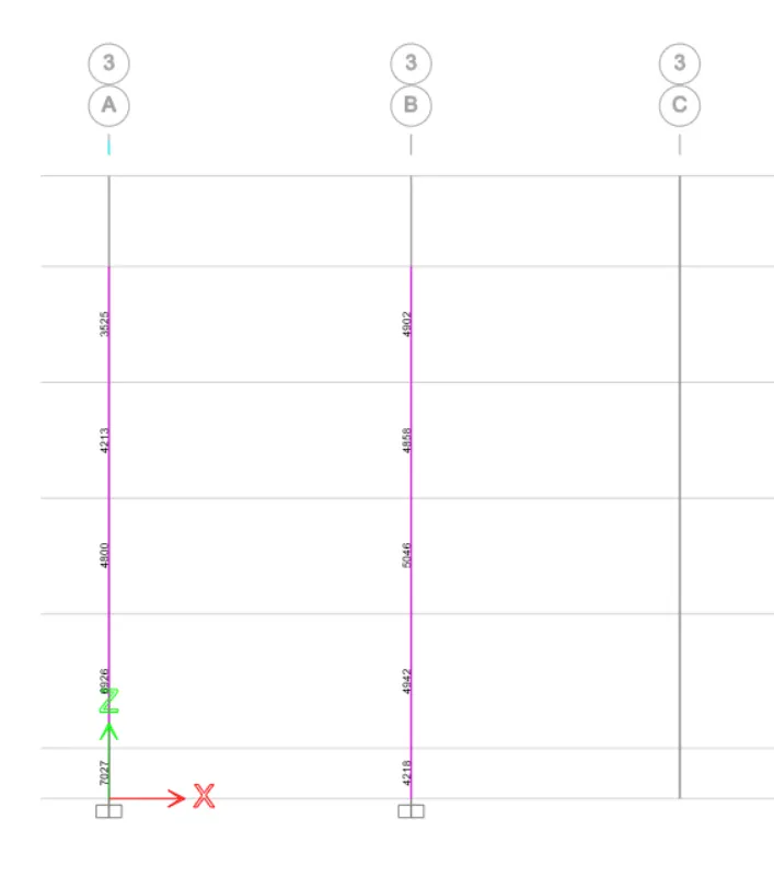
- And now if we want to check the shear reinforcement then go to the concrete frame design button after clicking on the button a drop-down list contains various options just go to the option Display Design Info just as shown in the below given image:
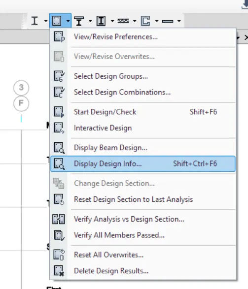
- After clicking on that a new dialogue box named as Display Concrete Frame Design Results opens in that dialogue box change the option Total Longitudinal Reinforcing into the option Shear Reinforcing just as shown in the below given image:
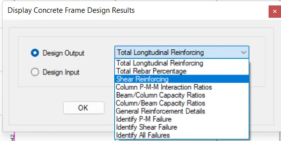
- The below is the result showing the Shear Reinforcing:
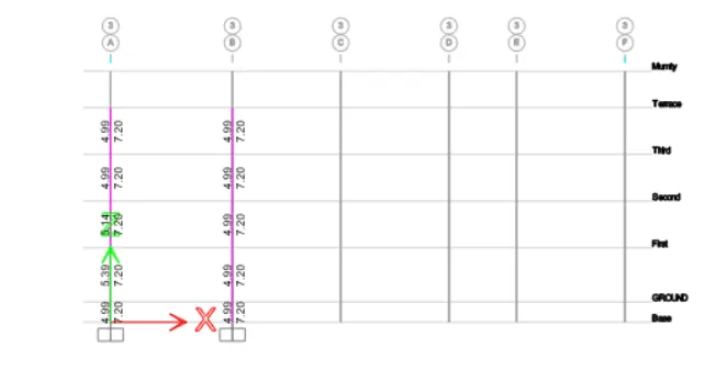
- Now we will be checking the elevation from the base to the terrace.
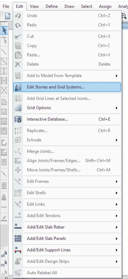
- So, in order to check the elevations first we need to go to the option Edit which is present at the left-top side of the screen after clicking the option Edit a drop-down list appears on that list there will be another option called Edit Stories and Grid Systems just click on that just as shown in the below image:
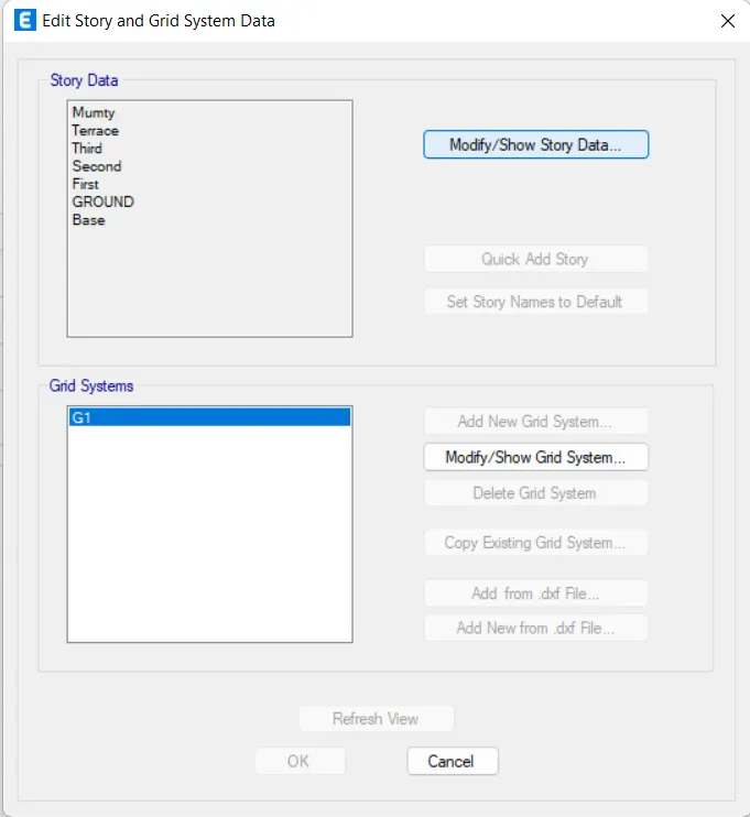
- After clicking the Edit Stories and Grid Systems option there will be a new window named as the Edit Stories and Grid Systems in that window just click on the option Modify/Show Story Data just as shown in the below figure:
- Below is the given result:
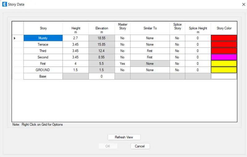
- Use this value when we are detailing the columns, so we should value of the heights and the elevations of the G+4 story building.
RESULTS: -
- Columns detail drawing for grid 3A:
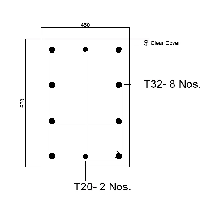
- Columns detail drawing for grid 3B: