Reinforcement Detailing of Beams from ETABS output
AIM -
- Design of RCC Moment Resisting frame structure in ETABS.
- Calculate value of maximum shear force as per clasue 6.3.3 (b) IS 13920-2016.
PROCEDURE -
1. Download and open the ETABS file provided:
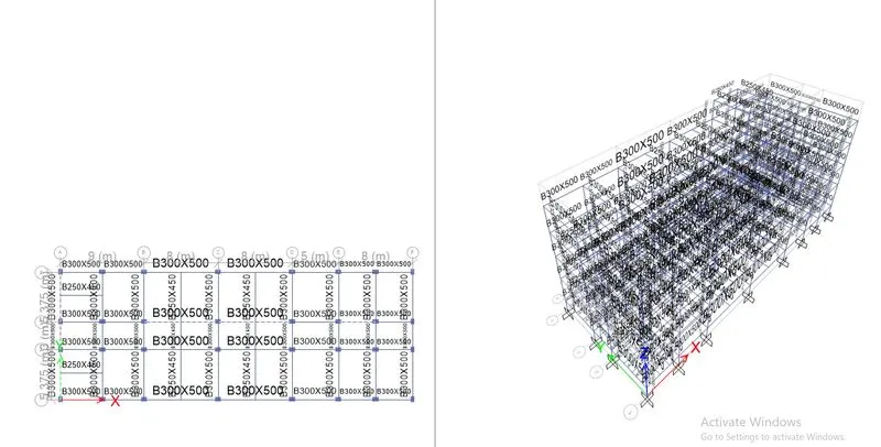
2. Check the model and Run analysis:
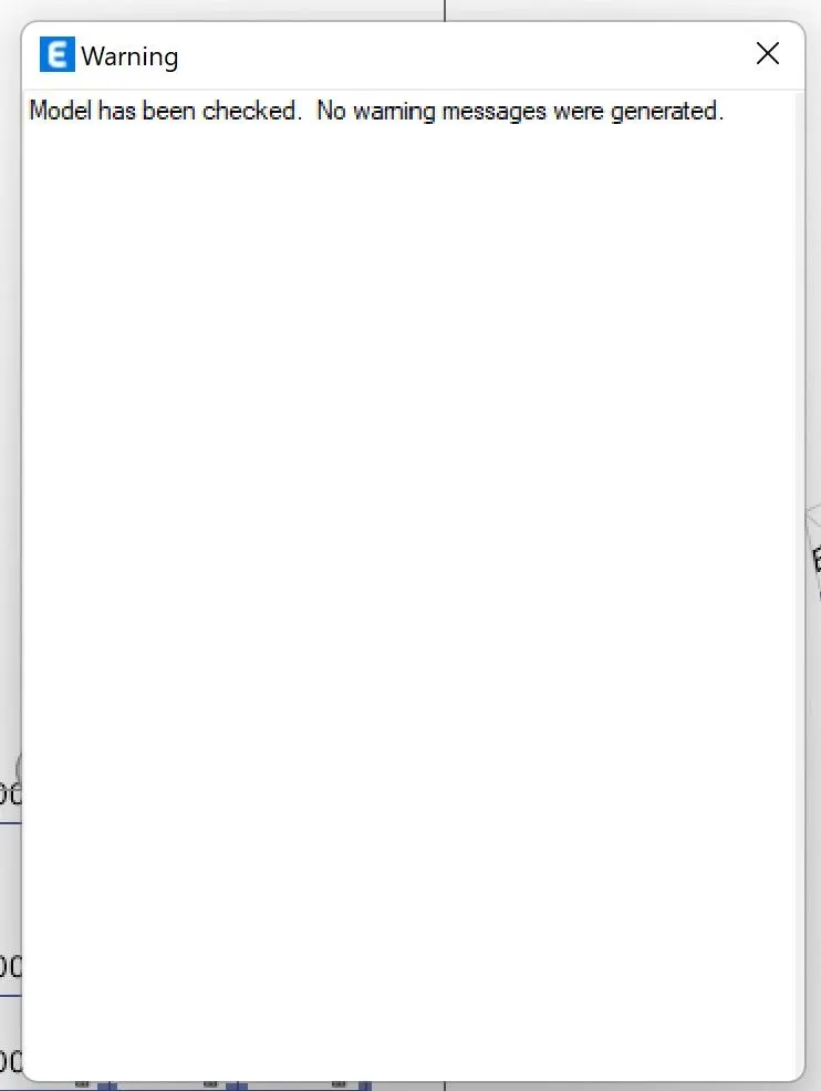
3. Select Design- Concrete frame design - Design comibantions :
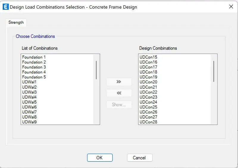
4. Again select design- Concrete frame design- start design/check :
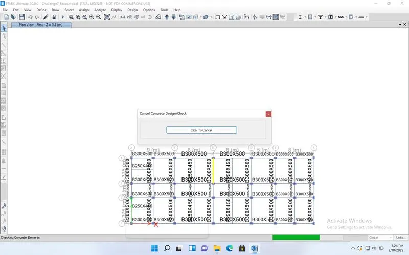
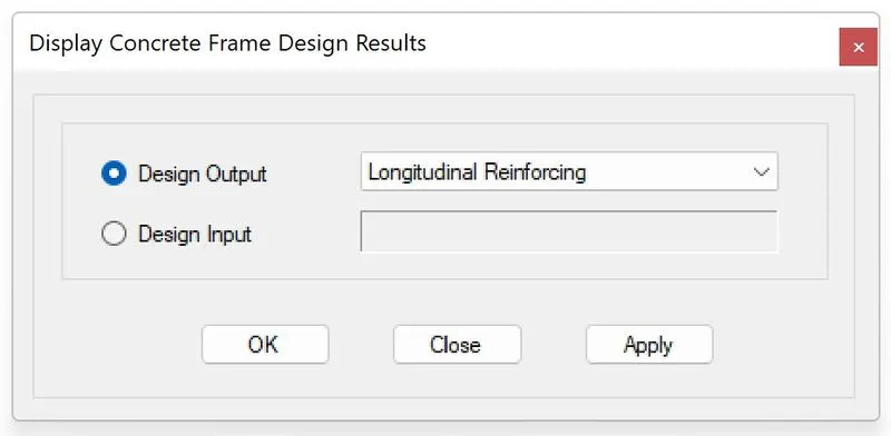
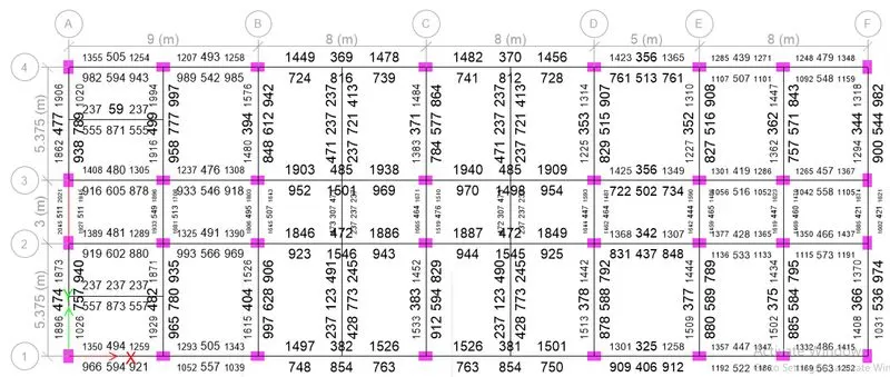
5. From design menu, select 'Display Design Info' and select Longitudinal reinforcement and press ok :
Result-
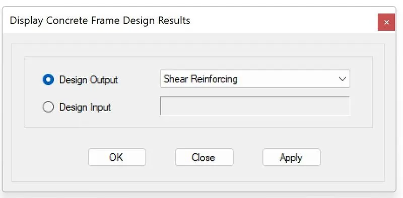
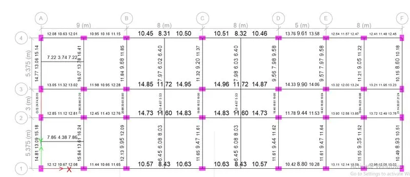
6. From design menu, select 'Display Design Info' and select shear reinforcement and press ok :
Result-
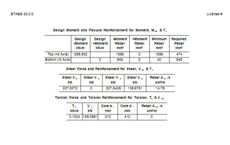
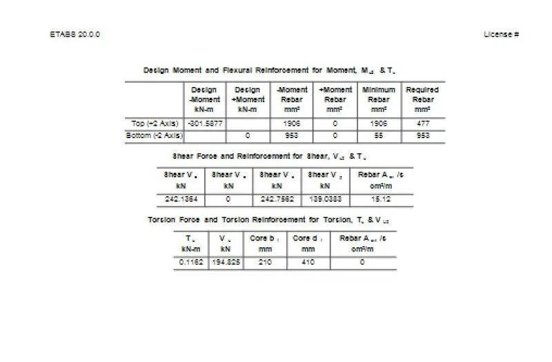
7. Now for 3 span continous beam on Grid A (first floor) -
- B33
- B34
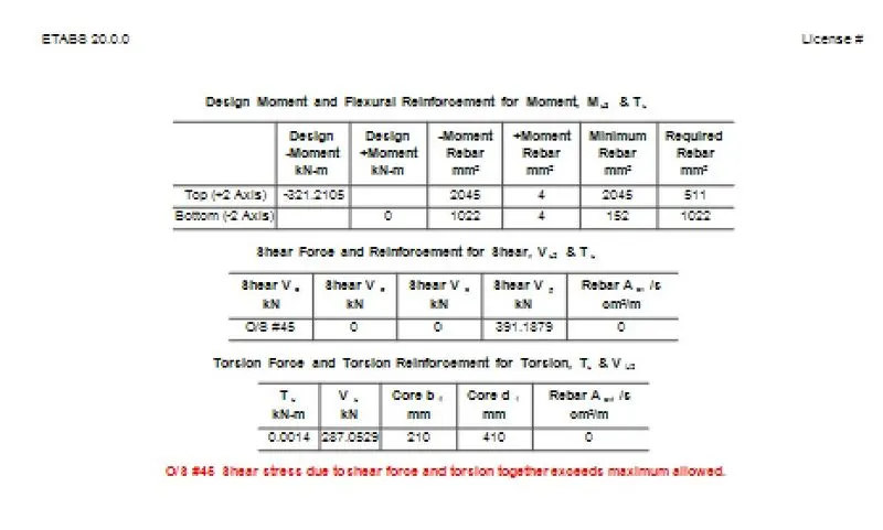
- B38
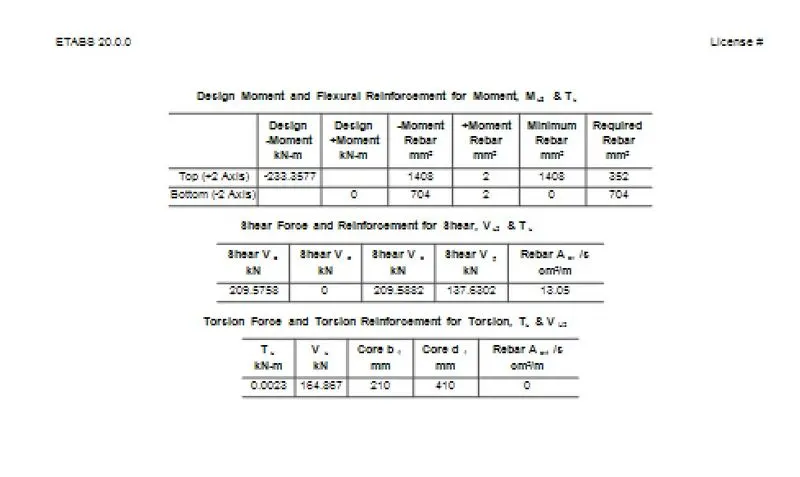
8. Now for continous 7 span Grid 3 (first floor) -
- B24
- B25
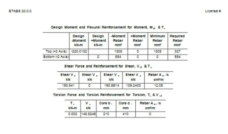
- B69
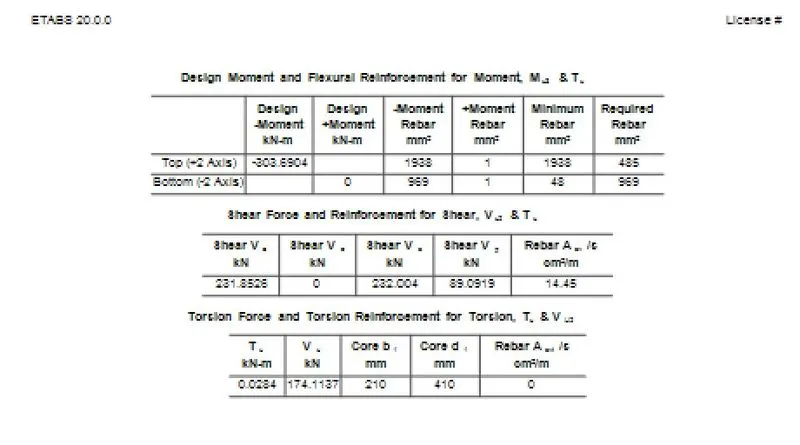
- B70
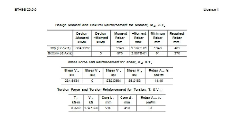
- B73
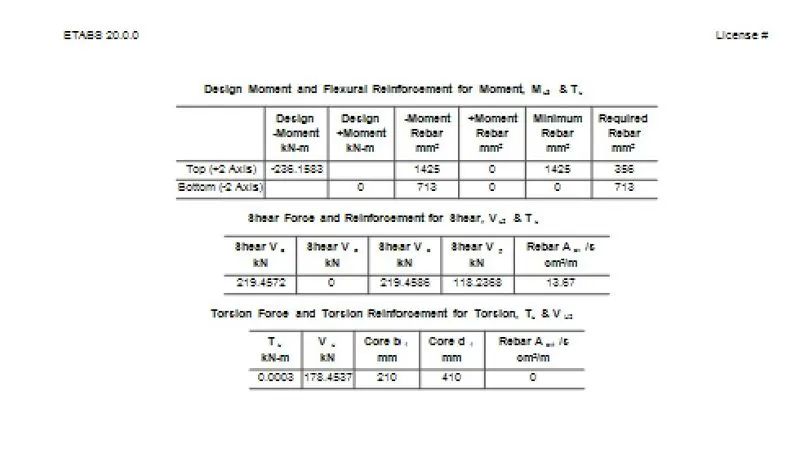
- B14
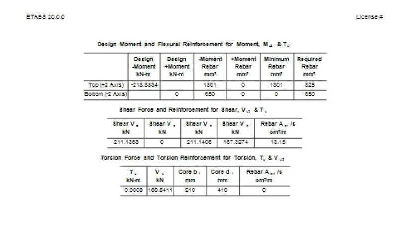
- B16
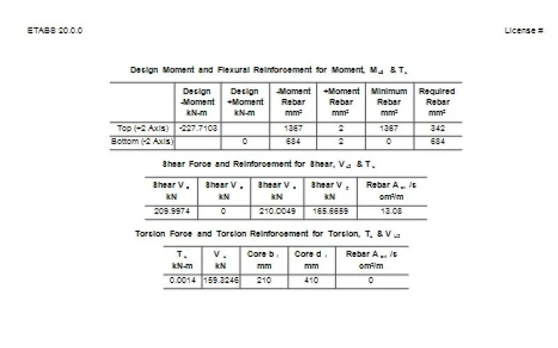
8. Reinforcement for grids A and 3 -
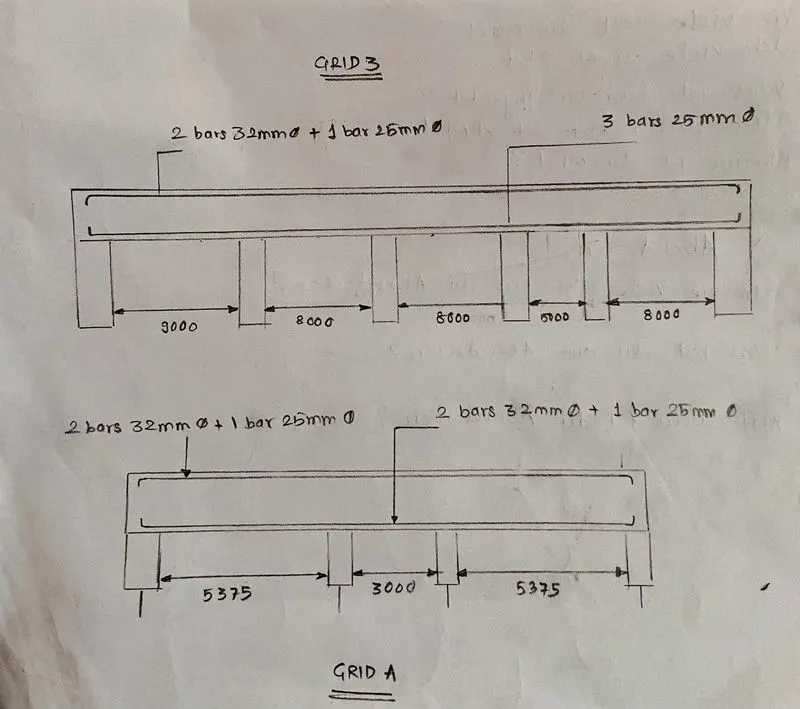
- 2 bars of 32mm dia are provided at top and bottom for 7 span continous in grid 3
- 1 bar of 25mm is added in the middle for beams B63, B70 and B73 for 7 span.
- 2 bars of 32mm dia are provided at top and 2 bars of 25mm are provided at the bottom for 3 span continous beam of grid A.
CONCLUSION-
- The middle beam of the grid A fails due to high shear stress, hence we see the o/s sign after applying shear reinforcement.
- shear failure in beams can be avoided by increasing the spacing between shear links, reducing the depth of the beams which results in less stiffness requirement.
- Shear failure can also be controled by proper grade of concrete.