Reinforcement Detailing of Beams from ETABS output
Q1. ) :-
Detail design of beams in Etabs 2018.
The ETABS file for a G+4 building is provided. Run the analysis and design the RCC Moment ResistingFrame. The following challenge deals specifically with two continuous beams in the 1st floor.
1) 3 span continuous beam along grid A
2) 7 span continuous beam along grid 3
Address the following issues thereafter.
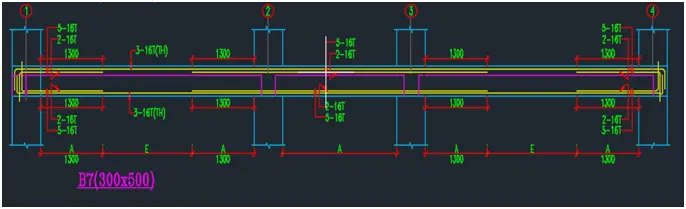
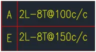
• Provide details of longitudinal and shear reinforcement for the two continuous beams. Sketch the beam elevation details or draft it using autocad software. A sample of how beam elevation details is prepared in consultancy firms is provided below. Participants can prepare it as per their preference:
• Calculate value of the maximum shear force in any one of the spans in the continuous beams, as per clause 6.3.3 (b) in IS 13920 – 2016. Also, confirm these values from shear force demand calculated by ETABS.Please note that if longitudinal reinforcement provided is more than required (as per ETABS results), the shear force demand will vary from what is provided by ETABS.
ANS :-
Aim:-
Design the beams precisely using Etabs 2018. to describe the longitudinal and shear reinforcement for the two presented continuous beams. to calculate the highest shear force possible in any given continuous beam span.
Introduction:-
Beams, which are horizontal structural elements, carry the lateral loads.
Beams support additional loads from the installation of services, finishes, and other wall loads in addition to the weight of the floor slab in traditional reinforced concrete structures.
To satisfy the requirements for the ultimate and serviceability limit states, the appropriate beam size must be chosen, along with the required amount of longitudinal and shear reinforcement.
The beams must then be properly reinforced after that.
Procedure:-
Step:-1
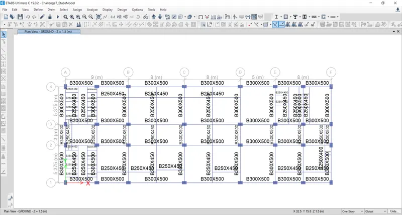
- The first step is to download the challenge by visiting the Challenge 7 page.
Once it has been downloaded, launch the Challenge in eTabs 2018 as instructed below.
Step:-2
- The load combinations must then be checked, as shown below.
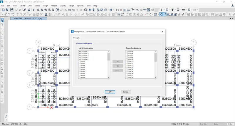
Step:-.
- Next, we must choose the 'Start Design/Check' option, as shown below, to begin the beam design.
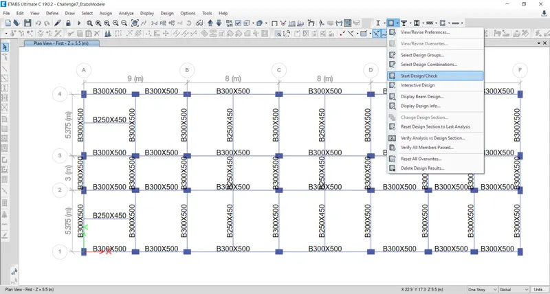
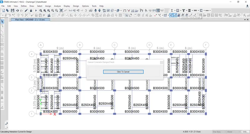
Step:-4
We must choose the 'Display Design Info' option after the beam design is finished, as shown below.
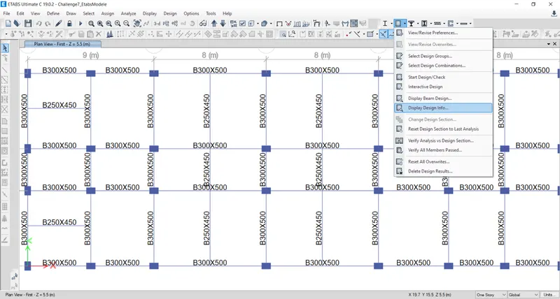
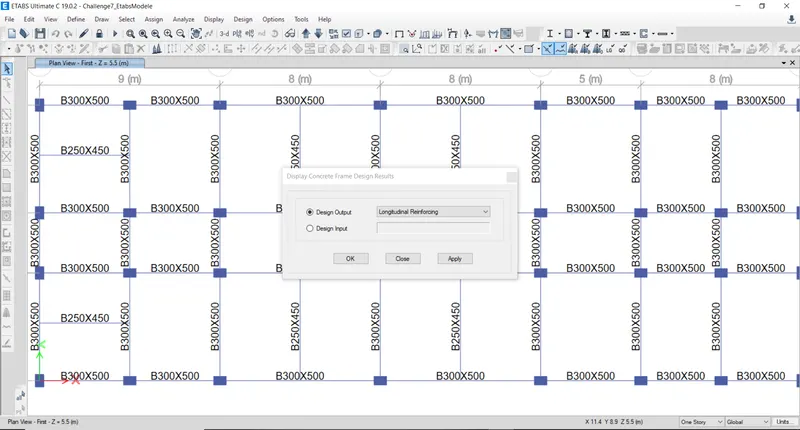
- When the 'Display Design Info' option is chosen, a new tab opens up. We choose the 'Longitudinal Reinforcing in the Design Output' option and then click the OK button, as shown below.
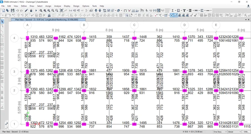
- Next the longitudinal reinforcement details will appear, as shown below.
Step :-5
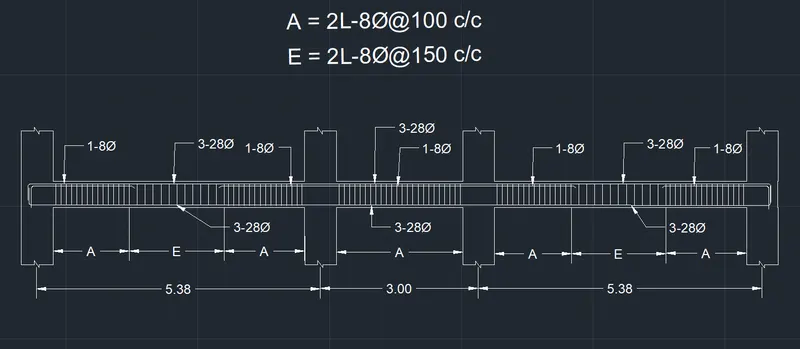
The reinforcement information and reinforcement diagram for a three-span continuous beam along Grid-A must then be provided.
The maximum Ast for the bottom support is 1766 mm2">mm2mm2, while the maximum Ast for the bottom middle is 702 mm2">mm2mm2.
The maximum ast for the top middle is 453 mm2">mm2mm2, and the top support's ast is 1889 mm2">mm2mm2.
As shown in the image below, we now offer 3-28 "> at the top and bottom.
Following that, we list 1 through 8 and state that "the continuous beam is supported at the top, as shown below.
Step:-6
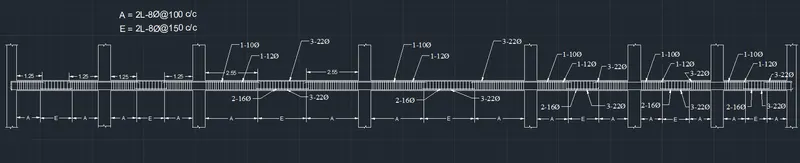
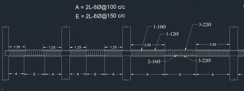
The reinforcement information must then be drawn along with the reinforcement diagram for a 7-span continuous beam along Grid-3.
The maximum Ast of the bottom support is 1061 mm2">mm2mm2 and the maximum Ast of the bottom middle is 1493 mm2">mm2mm2.
The maximum ast for the top middle is 479 mm2">mm2mm2, and the top support's ast is 1915 mm2">mm2mm2.
At the top and bottom, we now provide 3-22 ">, as shown in the figure below.
Top supports 1-10"> and 1-12"> are then provided, and 2-16 is then added. "As shown below, > at the bottom middle for the continuous beam.
Step:-7
- When we select the beam and right-click it after entering the information for the beam reinforcement, the new tab appears as shown below.
The next step is to choose the Details option from the Concrete Beam Design tab, as shown below.
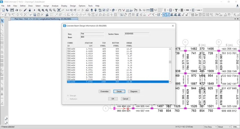
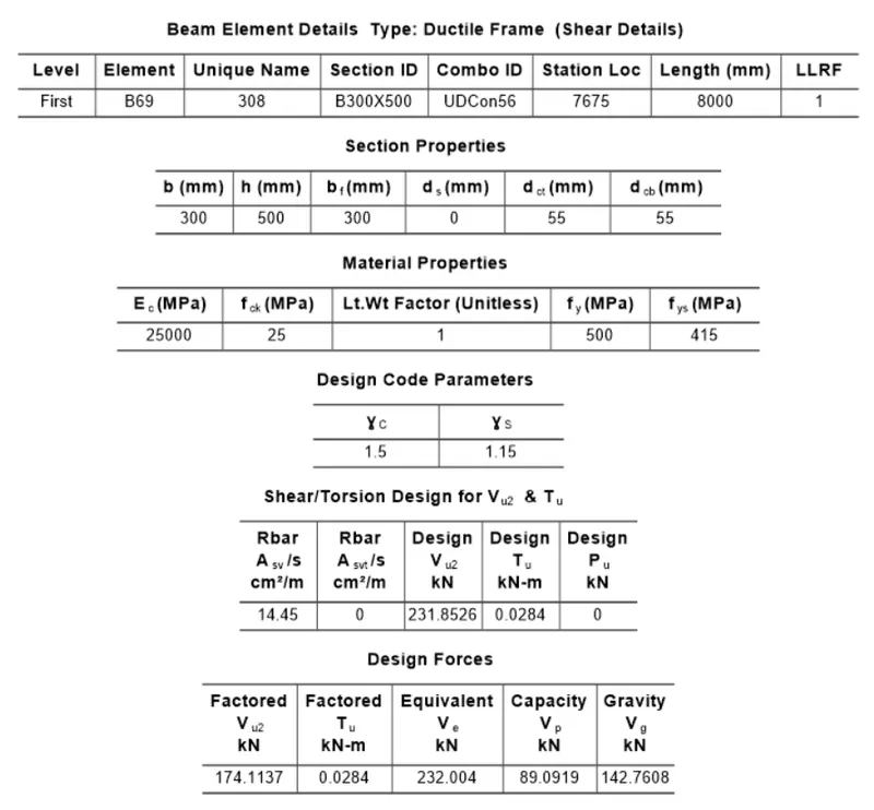
- Then, as displayed below, the Shear information will become accessible.
- Design force is 232 kN as per clause 6.3.3.
- Maximum shear force was determined to be 174.11 kN.
RESULT:-
- successfully designing a detailed beam with the Etabs program.
- The two continuous beams' longitudinal and shear reinforcement details were given.
- Additionally, the maximum shear force in continuous beams was calculated using the Etabs software.