Reinforcement Detailing of Beams from ETABS output
Aim:
To know the design of RC beam using ETABS analysis.
To know the basics of Beam reinforcement detailing with respect to primary standards.
To ensure the ductility reinforcement requirement by IS- 13920: 2016 has been satisfied in ETABS.
Given data:
The ETABS file for a G+4 building is provided. Run the analysis and design the RCC Moment Resisting Frame. The following challenge deals specifically with two continuous beams in the 1st floor.
1) 3 span continuous beam along grid A
2) 7 span continuous beam along grid 3
Address the following issues thereafter.
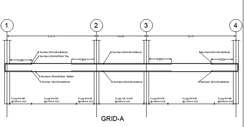
• Provide details of longitudinal and shear reinforcement for the two continuous beams. Sketch the beam elevation details or draft it using AutoCAD software. A sample of how beam elevation details is prepared in consultancy firms is provided below. Participants can prepare it as per their preference:
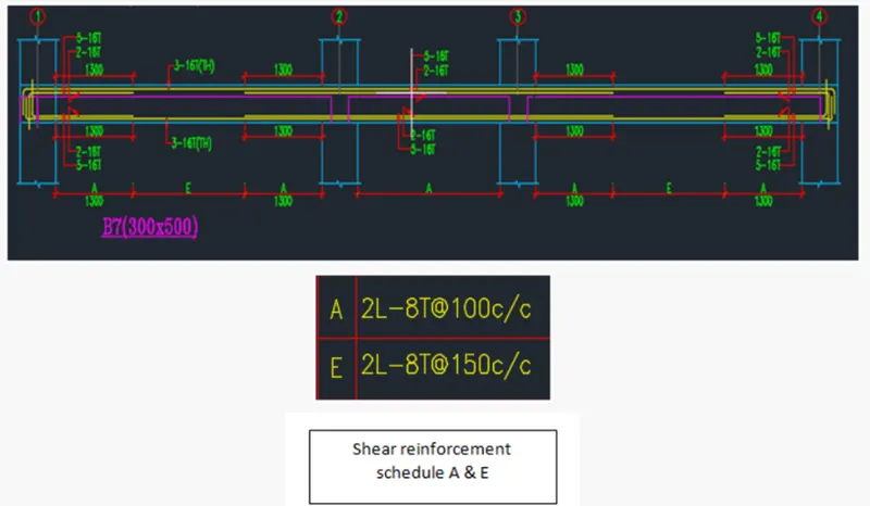
Provide reasons for failure of the middle span along grid A. What are the possible ways this issue can be resolved?
Calculate value of the maximum shear force in any one of the spans in both the continuous beams, as per clause 6.3.3 (b) in IS 13920 – 2016. Also, confirm these values from shear force demand calculated by ETABS. Please note that if longitudinal reinforcement provided is more than required (as per ETABS results), the shear force demand will vary from what is provided by ETABS.
Detailing rule of any concrete member:
If any one of the below conditions is required, then it should be included in RC beam design.
- Minimum reinforcement for shrinkage and temperature.
- Reinforcement required for limiting crack- width.
- Ultimate limit state design rebar requirement.
- Ductility rebar requirement.
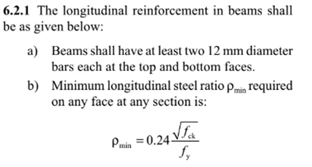
- Minimum longitudinal reinforcement as per IS- 13920:2016 clause 6.2.1 AS= 360 mm2.
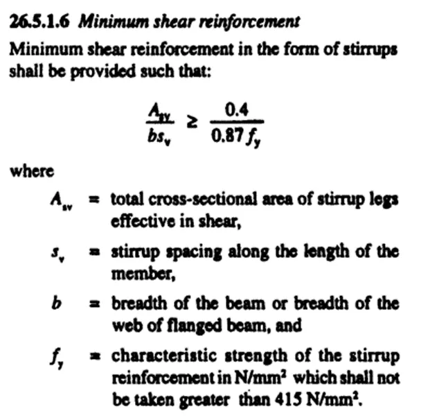
- Minimum shear (or) transverse reinforcement as per IS 456: 2000 clause 26.5.1.6 (Assuming spacing in the formula) Asv = 332mm.
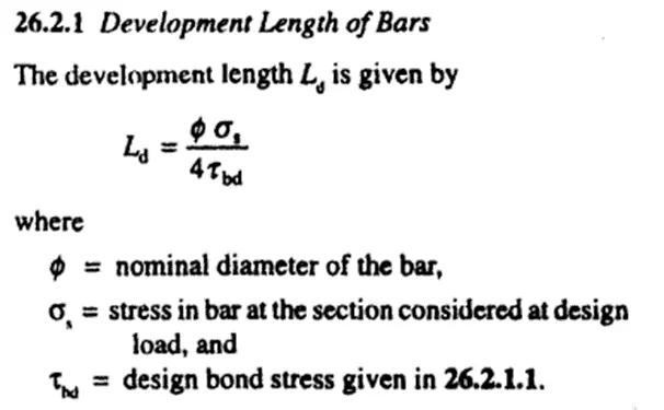
- Development length as per IS 456: 2000 clause 26.2.1 Ld =41 x diameter of bar.
Procedure:
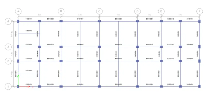
- Open the given structural plan
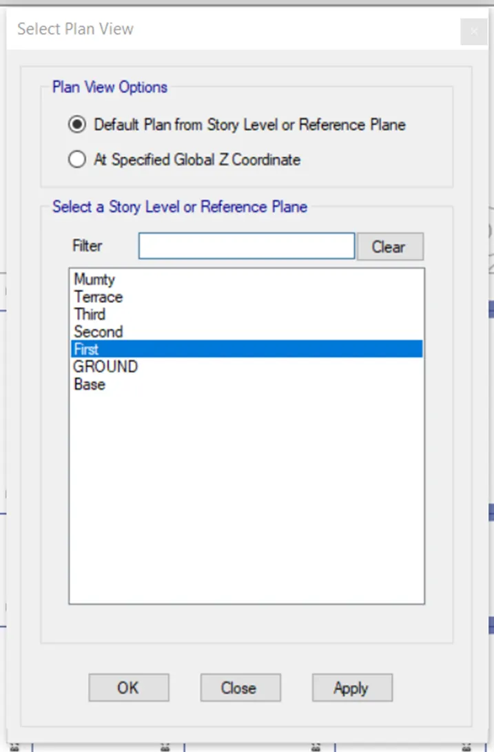
- Click Plan icon and select first floor.
- Click Run analysis icon.
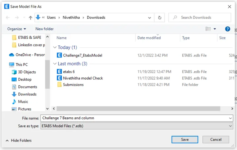
- Save the model.
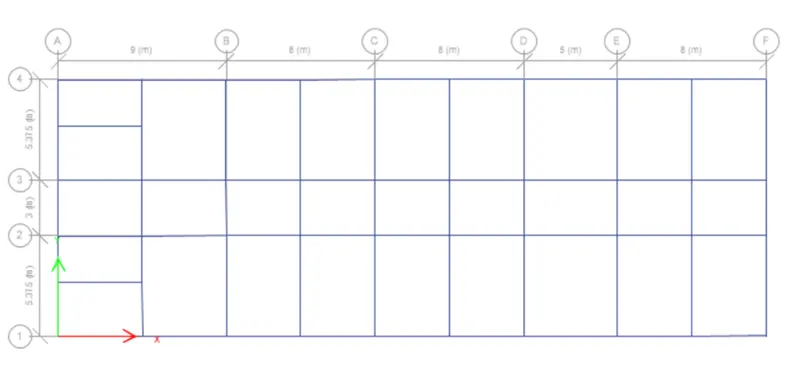
- The analysis is completed.
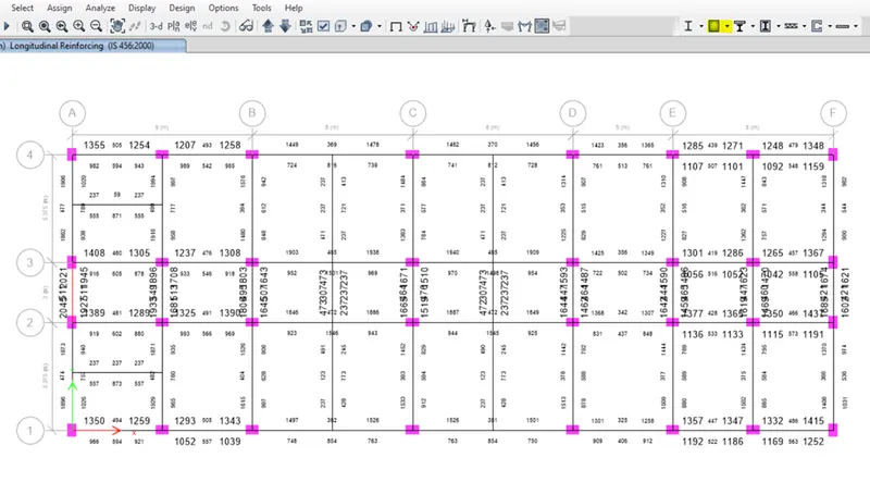
- Click Concrete frame design icon which helps to designs the longitudinal reinforcement and shear reinforcement for all the frames.
- Longitudinal reinforcement:
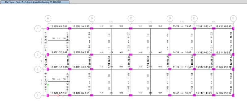
- Shear reinforcement:
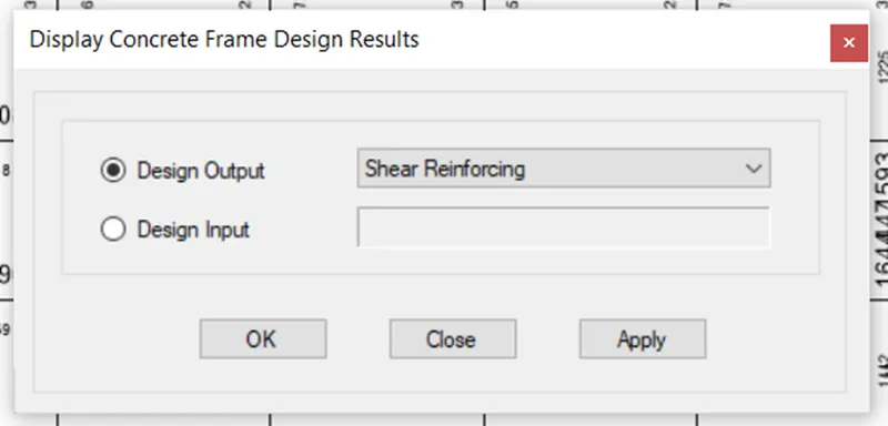
- Click Concrete frame design drop down -> Display design info -> shear reinforcement as design output.
- Right click on the beam to view the detail of the concrete beam design info.
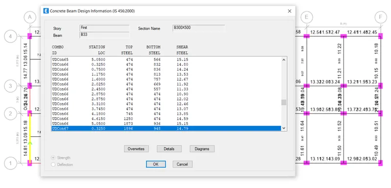
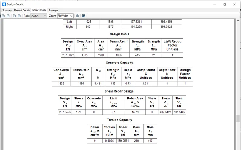
- Click Details in the above dialog box.
- Reasons for failure of the middle span along grid A:
- The midspan is failed due to over stress as shown.
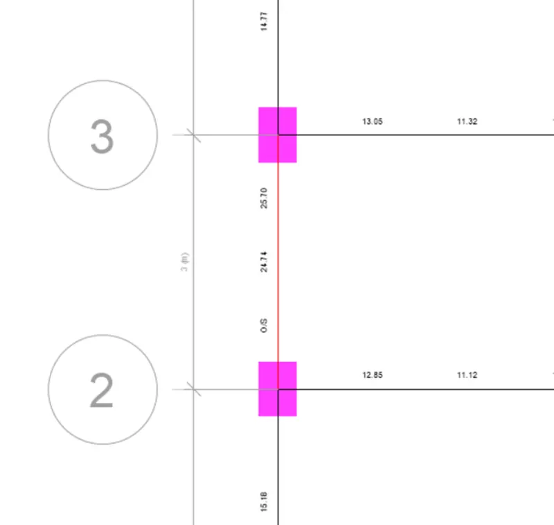
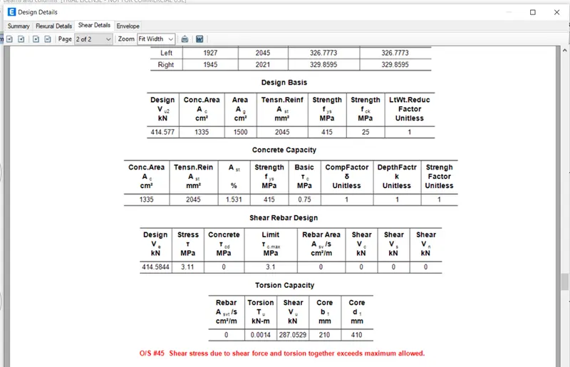
- Stress on the particular beam is beyond the codal requirement.
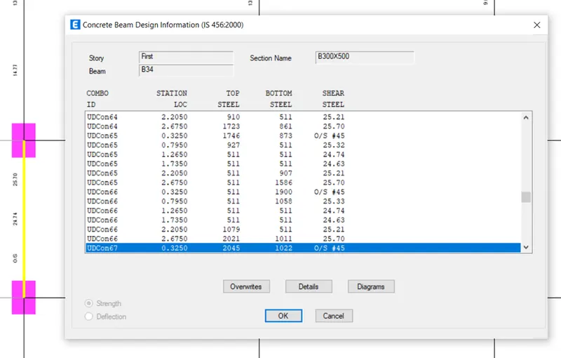
- Right click on the beam to view the details.
- Click Details.
- Solution to the failure:
- The following options can be adopted to pass the design.
- The loading in the particular beam should be reduced to overcome the shear stress.
- To increase the grade of concrete to increase the shear capacity of the concrete.
Longitudinal reinforcement of grid A (mm2):
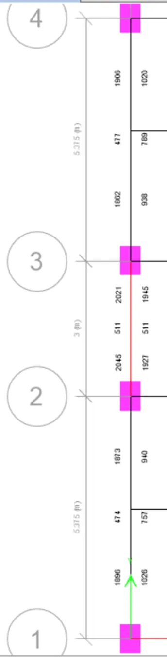
Longitudinal reinforcement of grid 3 (mm2):

Shear reinforcement of Grid A(cm2):
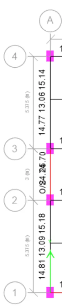
- Shear reinforcement of Grid 3 (cm2):

- Reinforcement guidelines:
- As per 13920:2016 clause 6.3.4 fig.4
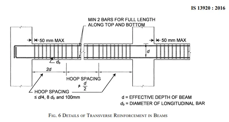
- The above-mentioned criteria from code is for regular beam design where as ETABS enhances its reinforcement details and other criteria to ensure the resistance for seismic behavior.
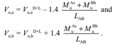
- As per IS 13920:2016 clause 6.3.3
- The sway shear force to right:
- MAs= 174 kNm
- MBh=293 kNm
- LAB =4.725m
- VD+L= 92kN
- Vu,a= 46 kN
- Vu,b= 230 kN
- The sway shear force to left:
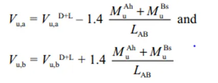
- MAh= 234 kNm
- MBs=155 kNm
- LAB =4.725m
- VD+L= 70kN
- Vu,a= 185 kN
- Vu,b= 45 kN
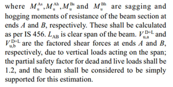
- As per the above formulated value, pick the higher value from Vu,a =185KN and Vu,b=230KN.
- So the minimum reinforcement for shear force resistance due to sway should be more than these value in the designed Beam.

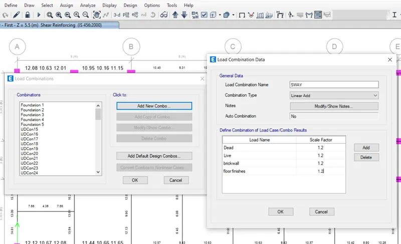
- In ETABS,
- Define new combination:
- Click Define-> Load combination -> Add new combo
- Add new combination as follow
- Click Display frame icon and give the following settings.
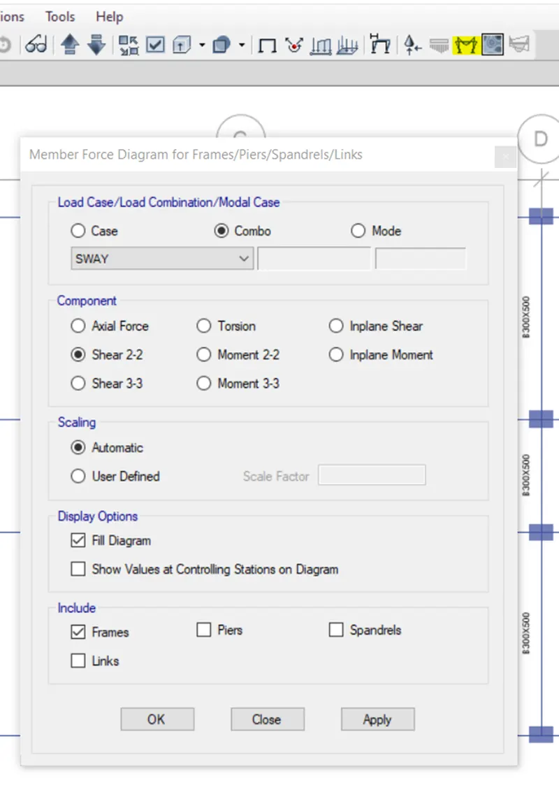
- Click Apply.
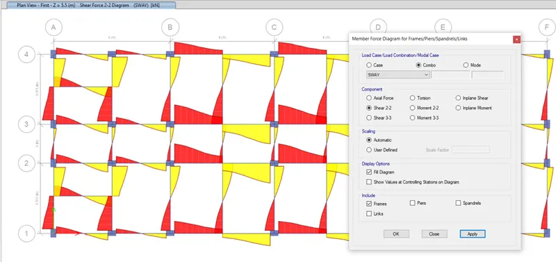
- Existing Shear capacity in Beam as per drawing:
(As per IS 456: 2000 clause 40.4)
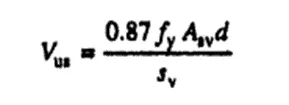
By the above formula,
Fy= 415 N/mm2.
ASV= 151 mm2.
d = 450mm
Sv = 100mm
Vus=245 KN
Hence shear rebar in drawing is okay as per IS 13920 code guidelines.
Result:
The maximum requirement arrived from the sway calculation is 230kN but the provided value is 245 kN. Hence it is safe.