Reinforcement Detailing of Beams from ETABS output
Aim:- Reinforcement Detailing of Beams from ETABS
Objectives:-
1) To know the beam design procedure by using Etab
2) To know the basic beam reinforcement deatiling with respect to primary standerd
3) To ensure the ductility reinforcement as per IS code 13920-2016
Introduction:-
- Beams are horizontal structural member used for the supporting lateral loads.
- In conventional reinforced concrete structures, beams usually receive load from the floor slab, but may also be subjected to other loads such as wall loads, finishes, services installation, etc.
- The design and detailing of RC beams involves the selection of the proper beam size and the quantity of longitudinal and shear reinforcement that will satisfy ultimate and serviceability limit state requirements.
- Afterwards, It is very important that the beam reinforcements are placed and arranged properly on site, to avoid construction error.
Procedure:-
Step:-1
- First we have to open the challange 7 and download the challenge.
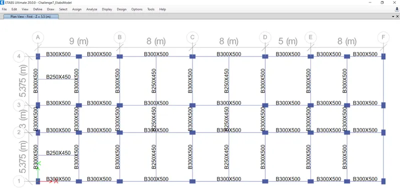
- After download the Challenge open it in the etabs 2023, as shown below.
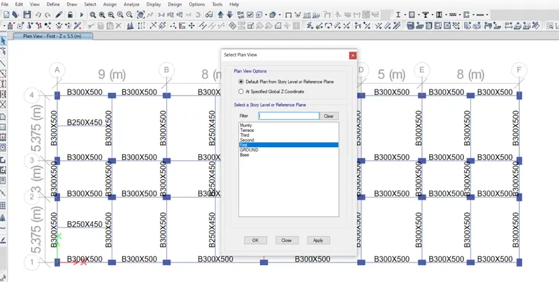
- open first floor plan
Step:-2
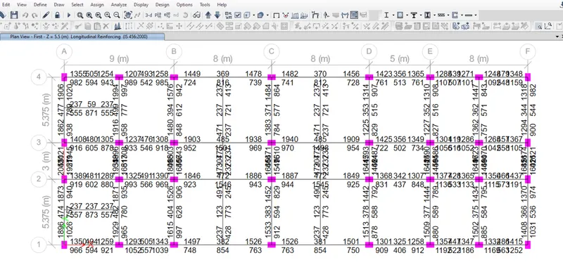
- Next we have to check the load combinations, as shown below.
- After clicking the icon, it starts checking the concrete design
Step:-3
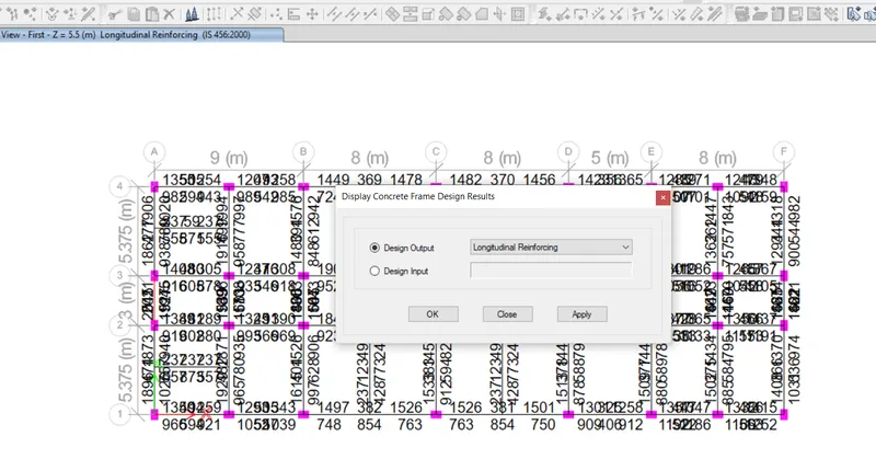
- select drop down button which is near to concrete frame design icon
- select display design info option
- one more window is diplayed on screen again select
Step:-4
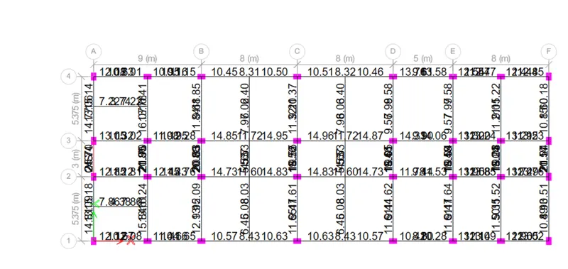
- After selecting the 'Display Design Info' option the new tab appears, In that we select the shear Reinforcing in the Design Output and click on the OK button, as shown below.
- below show the deail of shear reinforcement.
Step:-5
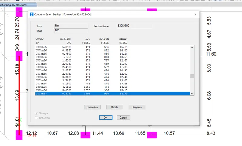
- we select the beam and right click on the beam then the new tab appears, as shown below.
- Next we need to click on the Details option in Concrete beam design tab, as shown below.
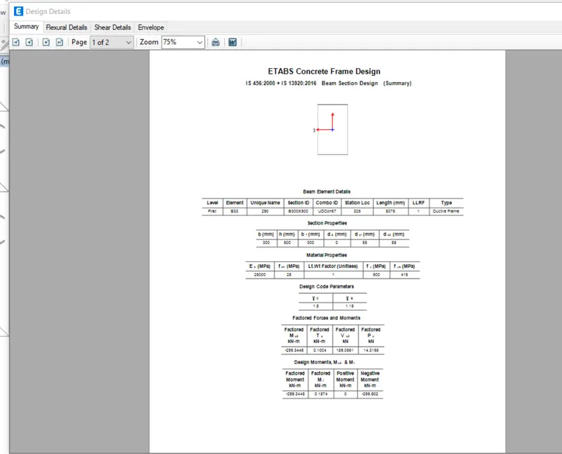
- Next the Shear details will be visible, as shown below.
- As per the clause 6.3.3 the design force is 232 kN.
- We got, Maximum Shear force = 174.11 kN.
Step:-6
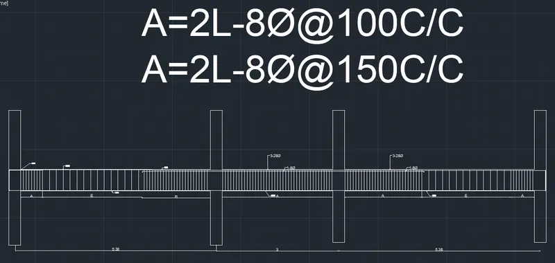
- Next we need to draw the Reinforcement diagram of 3 span continous beam along Grid-A, and also need to provide the reinforcement details.
- The maximum Ast for the bottom support is 2045mm2 and bottom middle 789 mm2
- The maximum Ast for the top support is 2021mm2 and top middle is 511mm2
- Now we provide 3-28Φ at the top and bottom, as shown in the below figure.
- Next we provide 1-8Φ at the top supports for the continuous beam, as shown below.
Step:-6
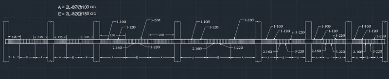
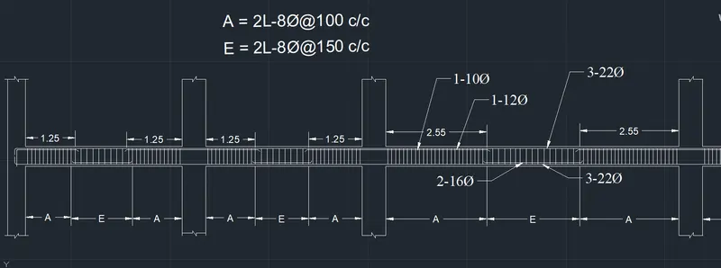
- Next we need to draw the Reinforcement diagram of 7 span continous beam along Grid-3, and also need to provide the reinforcement details.
- The maximum Ast for the bottom support is 1061mm2 and bottom middle is 1493mm2
- The maximum Ast for the top support is 1915mm2 and top middle is 479mm2
- Now we provide 3-22Φ at the top and bottom, as shown in the below figure.
- Next we provide 1-10Φ and 1-12Φat the top supports and we provide 2-16Φ at the bottom middle for the continuous beam, as shown below
Result:-
- Next the Shear details will be visible, as shown below.
- As per the clause 6.3.3 the design force is 232 kN.
- We got, Maximum Shear force = 174.11 kN.