Reinforcement Detailing of Beams from ETABS output
Aim - i) To design the beams in detail from the Etabs 2018.
ii) To provide the detailing of longitudinal and shear reinforcement for two continuous beams.
iii) To calculate the value of maximum shear force in any one of the spans in the continuous beams
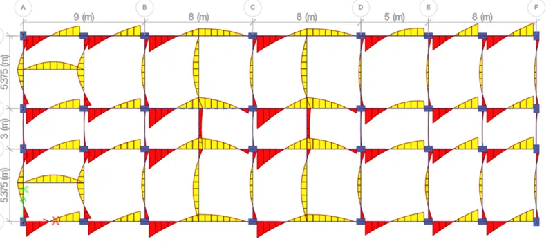
iv) To provide the reasons of failure of middle span along grid A.
Introduction -
- A beam is a structural element that primarily resists loads applied laterally to the beam's axis (an element designed to carry primarily axial load would be a strut or column). Beams are horizontal structural elements used for the supporting lateral loads.
- Its mode of deflection is primarily by bending. The loads applied to the beam result in reaction forces at the beam's support points.
- The total effect of all the forces acting on the beam is to produce shear forces and bending moments within the beams, that in turn induce internal stresses, strains and deflections of the beam.
- Beams are characterized by their manner of support, profile (shape of cross-section), equilibrium conditions, length, and their material.
- In conventional reinforced concrete structures, beams usually receive load from the floor slab, but may also be subjected to other loads such as wall loads, finishes, services installation, etc.
- The design and detailing of RC beams involves the selection of the proper beam size and the quantity of longitudinal and shear reinforcement that will satisfy ultimate and serviceability limit state requirements.
- Afterwards, It is very important that the beam reinforcements are placed and arranged properly on site, to avoid construction error.
Procedure -
Step 1)
i) Open the challange 7 attachment which are provided to us and download it.
ii) After downloading open the Challenge open it in the Etabs software.
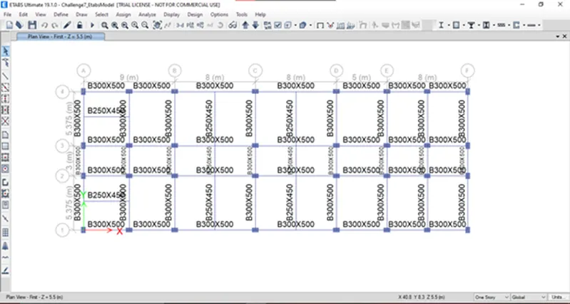
Step 2)
i) Now check the load combinations which are already created in given modeling file.
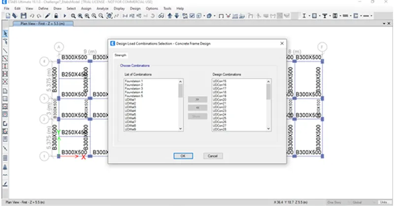
Step 3)
i) Before Run Analysis we have to check the model
ii) Click on Analyze
iii) Click on Check Model
iv) A structure is verified without any error and Model has been checked.
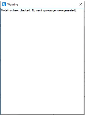
Step 4)
i) Now we have to start the beam design by selecting the 'Start Design/Check' option
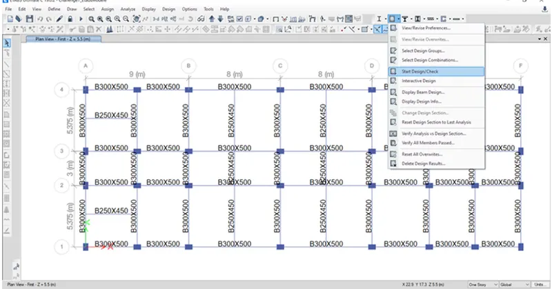
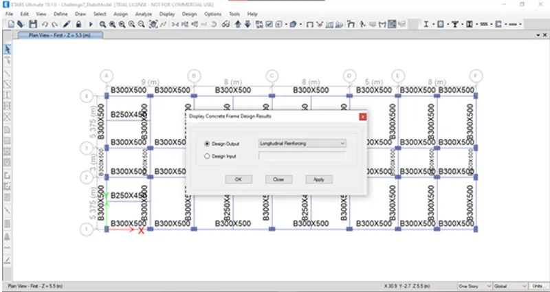
ii) Once you click on Start / Design check you will see Display concrete frame Design results box.
iii) Where you can select whatever design output you want
iv) So Click on Longitudinal Reinforcement.
Step 5)
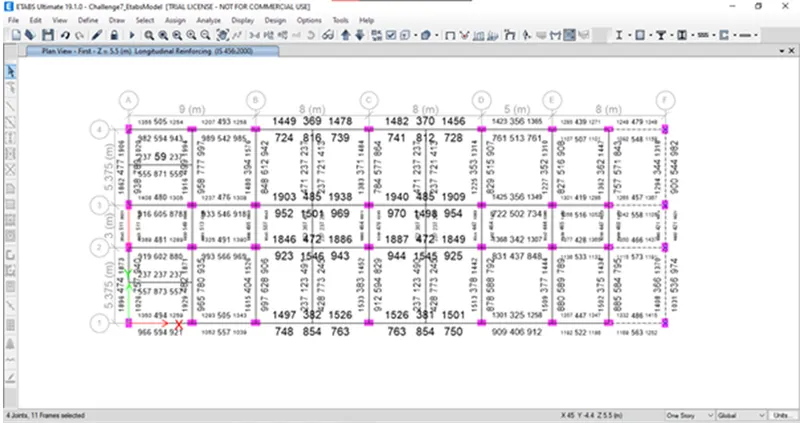
i) Once you click on, Longitudinal reinforcement details will appear
Step 6)
1) Reinforcement details along Grid A -
i) Max Ast at bottom support = 1945 mm2
ii) Max Ast at bottom middle = 789 mm2
iii) Max Ast at Top support = 2046 mm2
Max Ast at Top middle = 511mm2
Reinforcement Calculation -
1) For Top -
i) Total Ast required at top is = 2046
So we can provide
4 bars of diameter 20 mm and 4 bars of 16 mm satisfies the overall Ast
4 x T20 = 1256 mm2
4 x T16 = 804 mm2
4 X T20 + 4 x T16 = 2060 mm2.......Hence Satisfy.
2) For Bpttom -
i) Total Ast required at top is = 1945
So we can provide
3 bars of diameter 20 mm and 5 bars of 16 mm satisfies the overall Ast
3 x T20 = 942 mm2
4 x T16 = 1004 mm2
3 X T20 + 5 x T16 = 1946 mm2.....................Hence Satisfy.
3) For Shear details -
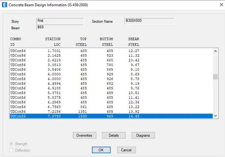
i) Right Click on and Click on Details
ii) Click on Shear Details
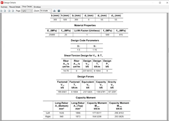
iii) As per Clause 6.3.3 we have to provide Spacing till 2d from the face of the column is 100 .
iv) It should not be more than that
v) So provide 3 legged stirrups of 10mm diameter with 100mm spacing throught the beam length .
Step 7)
1) Reinforcement details along Grid 3 -
i) Max Astat bottom support = 1042 mm2
ii) Max Ast at bottom middle = 1501 mm2
iii) Max Ast at Top support = 1940 mm2
iv) Max Ast at Top middle = 485 mm2
Reinforcement Calculation -
1) For Top -
i) Total Ast required at top is = 1940 mm2
So we can provide
3 bars of diameter 20 mm and 5 bars of 16 mm satisfies the overall Ast
3 x T20 = 942 mm2
4 x T16 = 1004 mm2
4 X T20 + 4 x T16 = 1946 mm2.......................Hence Satisfy .
2) For Bottom -
i) Total Ast required at top is = 1501 mm2
So we can provide
3 bars of diameter 20 mm and 3 bars of 16 mm satisfies the overall Ast
3 x T20 = 942 mm2
3 x T16 = 603 mm2
3 X T20 + 5 x T16 = 1545 mm2.......................Hence Satisfy.
3) For Shear details -
i) Right Click on and Click on Details
ii) Click on Shear Details
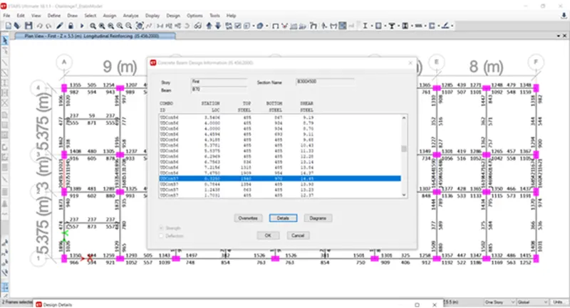
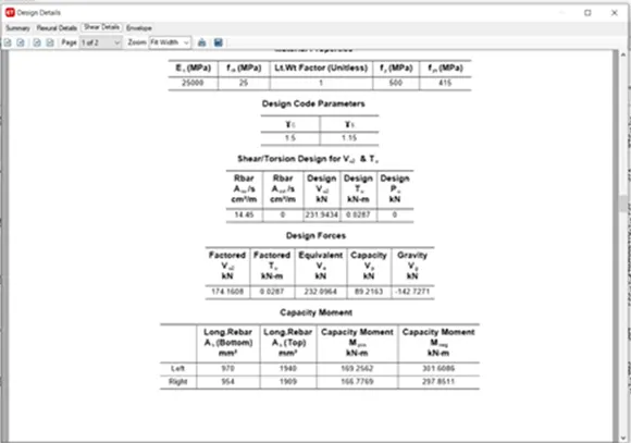
iii) As per Clause 6.3.3 we have to provide Spacing till 2d from the face of the column is 100.
iv) It should not be more than that
v) So provide 3 legged stirrups of 8mm diameter with 100mm spacing throught the beam length on both side
vi) And provide 3 legged stirrups of 8mm diameter with 150mm spacing at mid span.
Step 8)
i) Now we have to do Check for Sway shear .
A) For Right Sway
We know that the formula to calcuate
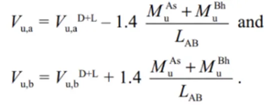
From Etabs Model results substitute the value -
i) VuD+L = 92 Kn
ii) Mas = 176 kn-m
iii) Mbh = 295 kn
iv) Lab = 4.725 m
Put this value in above eqn
we get ,
Vu,a = 48 Kn
Vu,b = 230 Kn
B) For Left Sway
i) Follow the same process
ii) We know the formula
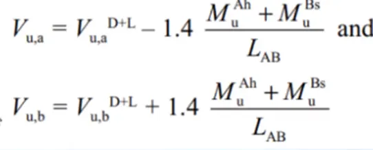
From Etabs Model results substitute the value -
i) VuD+L = 74 Kn
ii) Mah = 236 kn
iii) Mbs = 150 kn
iv) Lab = 4.725 m
Put this value in above eqn
we get ,
Vu,a= 190 Kn
Vu,b = 50 Kn
C) Existing Shear capacity in beam as per Is 456-2002
i) We know the formula -
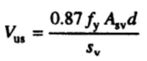
Put the values -
i) fy = 415 N/mm2
ii) Asv = 151 mm2
iii) Spacing = 100 mm
iv) d = 450 mm
put this value in above eqn
we get
Vus = 246 kn > 230 kn ( Shear sway)........... ( Hence Safe )
Results -
Calculate value of the maximum shear force in any one of the spans in both the continuous beams, as per clause 6.3.3 (b) in IS 13920 – 2016.
As we have already calculated the value of shear force as per IS 13920 - 2016 Clause 6.3.3 (b)
We get the Shear sway value Right and Left support within limit
246 kn > 230 Kn ...................( Safe )