Reinforcement Detailing of Beams from ETABS output
Challenge 7 – Detailed design of concrete buildings -1
Detail design of beams in Etabs 2018.
The ETABS file for a G+4 building is provided. Run the analysis and design the RCC Moment ResistingFrame. The following challenge deals specifically with two continuous beams in the 1st floor.
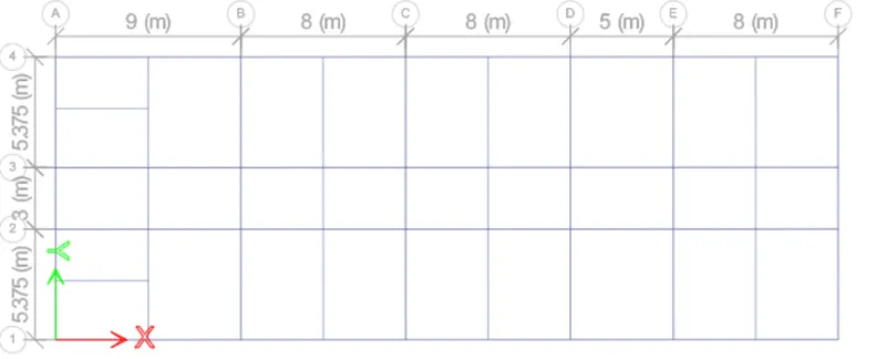
1) 3 span continuous beam along grid A
2) 7 span continuous beam along grid 3
Address the following issues thereafter.
• Provide details of longitudinal and shear reinforcement for the two continuous beams. Sketch the beam elevation details or draft it using autocad software. A sample of how beam elevation details is prepared in consultancy firms is provided below. Participants can prepare it as per their preference:
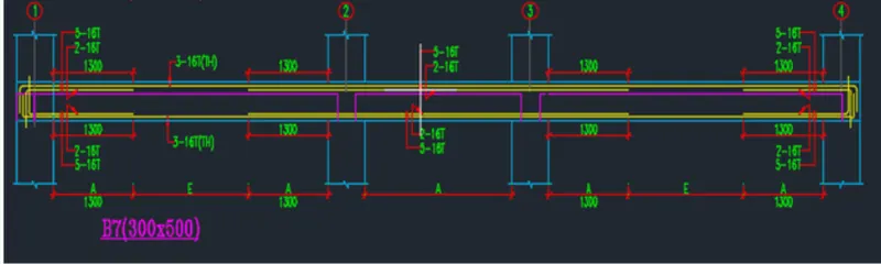
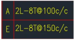
• Provide reasons for failure of the middle span along grid A. What are the possible ways this issue can be resolved?
• Calculate value of the maximum shear force in any one of the spans in both the continuous beams, as per clause 6.3.3 (b) in IS 13920 – 2016. Also, confirm these values from shear force demand calculated by ETABS.Please note that if longitudinal reinforcement provided is more than required (as per ETABS results), the shear force demand will vary from what is provided by ETABS.
ANSWER :
AIM:
i) To design the beams in detail from the Etabs 2018.
ii) To provide the detailing of longitudinal and shear reinforcement for two continuous beams .
iii) To calculate the value of maximum shear force in any one of the spans in the continuous beams
iv) To provide the reasons of failure of middle span along grid A.
Introduction -
1) Beams are horizontal structural elements used for the supporting lateral loads.
2) In conventional reinforced concrete structures, beams usually receive load from the floor slab, but may also
be subjected to other loads such as wall loads, finishes, services installation, etc.
3) The design and detailing of RC beams involves the selection of the proper beam size and the quantity of longitudinal
and shear reinforcement that will satisfy ultimate and serviceability limit state requirements.
4) Afterwards, It is very important that the beam reinforcements are placed and arranged properly on site,
to avoid construction error.
PROCEDURE:
STEP 1:
i) Open the challange 7 attachment which are provided to us and download it .
ii) After downloading open the Challenge open it in the Etabs software .
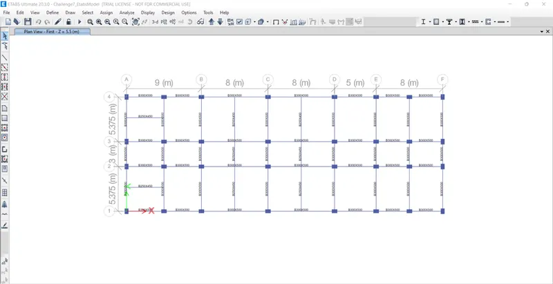
Step 2)
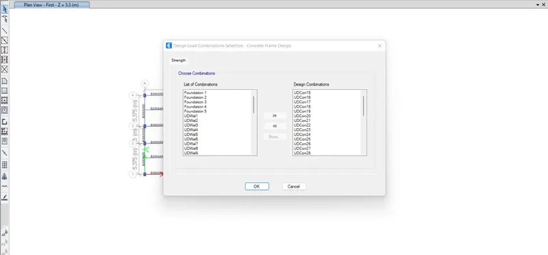
i) Now check the load combinations which are already created in given modeling file .
Step 3)
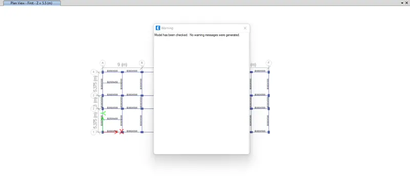
i) Before Run Analysis we have to check the model
ii) Click on Analyze
iii) Click on Check Model
iv) A structure is verified without any error and Model has been checked .
Step 4)
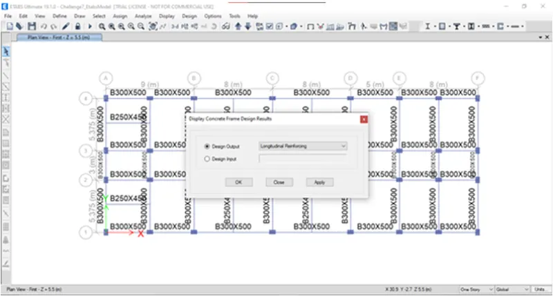
i) Now we have to start the beam design by selecting the 'Start Design/Check' option .
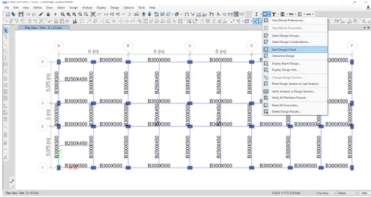
ii) Once you click on Start / Design check you will see Display concrete frame Design results box .
iii) Where you can select whatever design output you want
iv) So Click on Longitudinal Reinforcement .
Step 5)
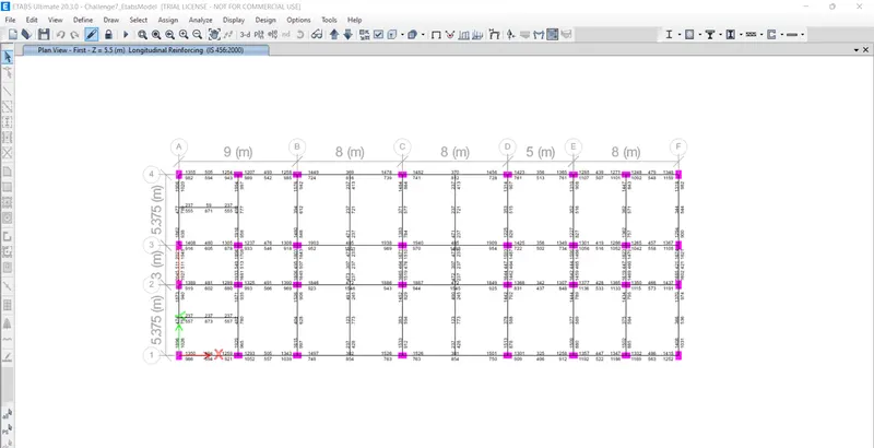
i) Once you click on , Longitudinal reinforcement details will appear .
Step 6) :
1) Reinforcement details along Grid A -
i) Max Ast">Ast at bottom support = 1026 mm2
ii) Max Ast">Ast at bottom middle = 757 mm2
iii) Max Ast">Ast at Top support = 1896 mm2
iv) Max Ast">Ast at Top middle = 474 mm2
Reinforcement Calculation -
1) For Top -
i) Total Ast required at top is = 1896 MM^2
So we can provide
3 bars of diameter 20 mm and 5 bars of 16 mm satisfies the overall Ast
3 x T20 = 942 mm2
5 x T16 = 804 mm2
3 X T20 + 5 x T16 = 1946mm2.......................Hence Satisfy .
2) FOR BOTTOM: -
i) Total Ast required at top is = 1026 MM^2.
So we can provide
2 bars of diameter 20 mm and 2 bars of 16 mm satisfies the overall Ast
2 x T20 = 628 mm2
2 x T16 = 402 mm2
2X T20 + 2 x T16 = 1030 mm2........................Hence Satisfy .
3) For Shear details -
i) Right Click on and Click on Details
ii) Click on Shear Details
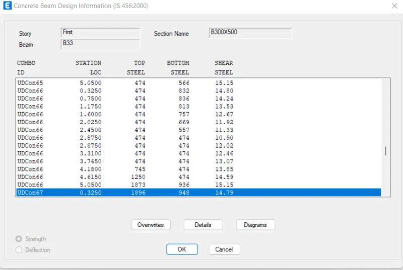
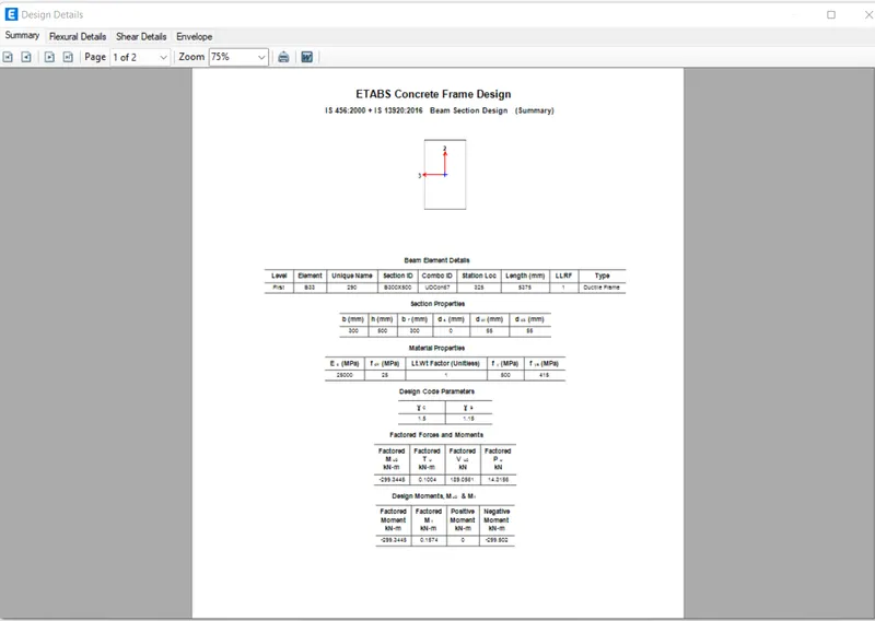
FIG.
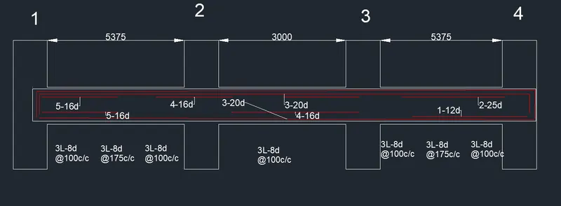
iii) As per Clause 6.3.3 we have to provide Spacing till 2d from the face of the column is 100 .
iv) It should not be more than that
v) So provide 3 legged stirrups of 10mm diameter with 100mm spacing throught the beam length .
REINFORCMENT DETAIL AT GRID 3:

FIG.
Step 8)
i) Now we have to do Check for Sway shear .
A) For Right Sway
We know that the formula to calcuate :
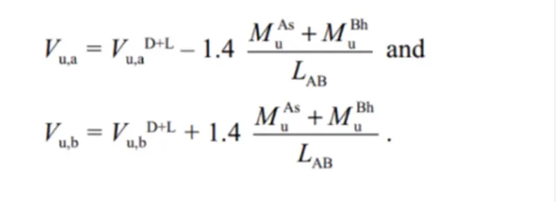
From Etabs Model results substitute the value -
i) VuD+L= 92 Kn
ii) Mas= 176 kn-m
`ii) Mbh= 295 kn&n`
iv) Lab = 4.725 m
Put this value in above eqn
we get ,
Vu,a= 48 Kn
Vu,b = 230 Kn
B) For Left Sway
i) Follow the same process
ii) We know the formula
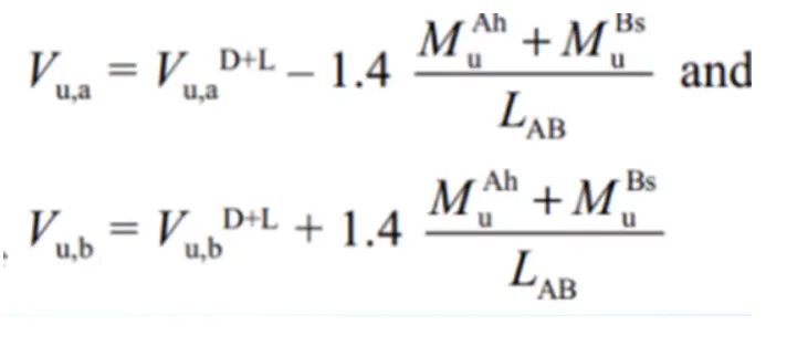
From Etabs Model results substitute the value -
i) VuD+L= 74 Kn
`i) Mah= 23`
iii) Mbs= 150 kn
iv) Lab = 4.725 m
Put this value in above eqn
we get ,
`V_(u,a)`= 190 Km
Vu,b = 50 Km
C) Existing Shear capacity in beam as per Is 456-2002
i) We know the formula -
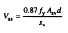
Put the values -
i) fy = 415 N/mm2
ii) Asv = 151 mm2
iii) Spacing = 100 mm
iv) d = 450 mm .
put this value in above eqn
we get
VusVus) = 246 kn............................................> 230 kn ( Shear sway)........... ( Hence Safe )
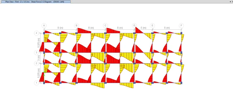
Results -
i) Beam Design is done successfully with detailed reinforcement .
ii) Provide reasons for failure of the middle span along grid A. What are the possible ways this issue can be resolved ?
1) The main reason of failure of middle span along grid A is shear stress is exceeded the limiting value
2) This may be beacause of the higher Shear force acting on that beam and due to provision of weak shear
reinforcement at the end supports .

3) This Issue can be Solved by -
i) By providing Higher grade of concrete in that particular section
ii) Or by reducing the Shear force in that beam section
iii) Or by providing higher shear reinforcement which can resist the shear force in that section
iii) Calculate value of the maximum shear force in any one of the spans in both the continuous beams,
as per clause 6.3.3 (b) in IS 13920 – 2016.
As we have already calculated the value of shear force as per IS 13920 - 2016 Clause 6.3.3 (b)
We get the Shear sway value Right and Left support within limit
246 kn > 230 Kn ...................( Safe )