Reinforcement Detailing of Beams from ETABS output
Challenge 7 – Detailed design of concrete buildings -1
Question: Detail design of beams in Etabs 2018.
The ETABS file for a G+4 building is provided. Run the analysis and design the RCC Moment ResistingFrame. The following challenge deals specifically with two continuous beams in the 1st floor.
1) 3 span continuous beam along grid A
2) 7 span continuous beam along grid 3
Address the following issues thereafter.
• Provide details of longitudinal and shear reinforcement for the two continuous beams. Sketch the beam elevation details or draft it using autocad software. A sample of how beam elevation details is prepared in consultancy firms is provided below. Participants can prepare it as per their preference:
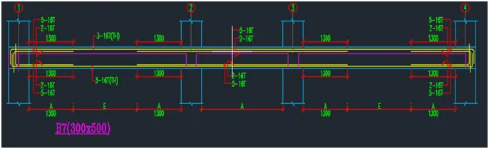
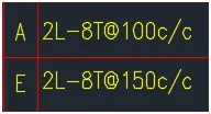
• Provide reasons for failure of the middle span along grid A. What are the possible ways this issue can be resolved?
• Calculate value of the maximum shear force in any one of the spans in both the continuous beams, as per clause 6.3.3 (b) in IS 13920 – 2016. Also, confirm these values from shear force demand calculated by ETABS.Please note that if longitudinal reinforcement provided is more than required (as per ETABS results), the shear force demand will vary from what is provided by ETABS.
AIM:
We have to design the beams in the software ETABS in a very detailed manner. ETABS sotware allows the user to detail the beams and any other members of the structure in a very detailed manner with accurate results. We all know that the ETABS is an engineering software which is used to design and analyse the multi-stirey buildings with their different modelling tool,codes based load prescriptions and analysis methods. Basic and advanced systems under static or dynamic conditions may be evaluated using the ETABS software. So here we are going to design the Beams for the below given plan with detailing.
- Provide details of longitudinal and shear reinforcement for the two continuous beams. Sketch the beam elevation details or draft it using autocad software. A sample of how beam elevation details is prepared in consultancy firms is provided below. Participants can prepare it as per their preference:
PROCEDURE:
- So in order to design the beams in ETABS software,first of all download the attachment that is already given in the question.
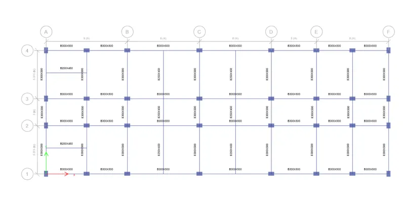
- The plan is already given in the question.
- Go and download the plan and open that plan in the ETABS software.
- The plan of the structure is given below in the image:
- Provide details of longitudinal and shear reinforcement for the two continuous beams. Sketch the beam elevation details or draft it using autocad software. A sample of how beam elevation details is prepared in consultancy firms is provided below. Participants can prepare it as per their preference:
- So first of all we have to provide the detalis of the longitudinal and the shear reinforcement for the two continuous beams.
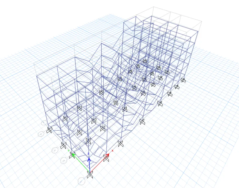
- First of all we have to do the Run analysis,and to do the run analysis simply just press F5 and now the run analysis has been completed just as shown in the below image:
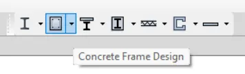
- After doing the run analysis just go to the option Concrete frame design at the top of the screen and click on the Concrete Frame design option just as shown in the below image:
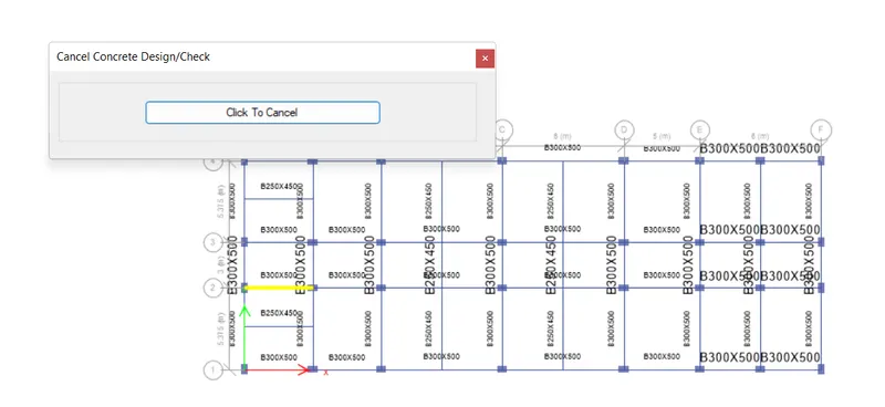
- Now click on the Concrete Frame Icon. Just after clicking that icon it starts checking the Concrete design just as shown in the below given image.
- The result after running the Concrete Design/Check is given below:
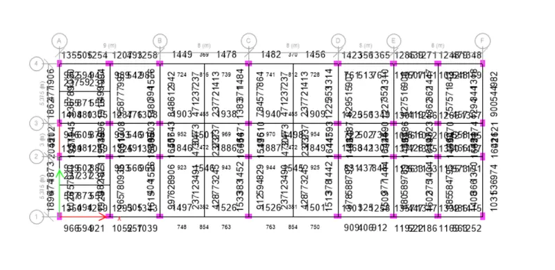
- Now the check has been done as we can see in the above given image.
- So as we know that we have to do the beam detailing in the below given grids:
1) 3 span continuous beam along grid A.
2) 7 span continuous beam along grid 3.
- And for doing this first we have to go to the Plan View,where we have the column detailing and the beam detailing.
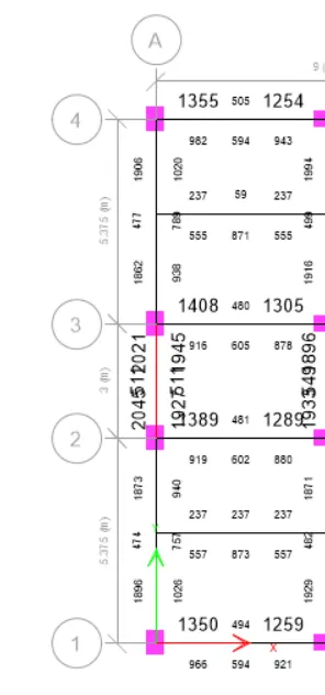
- Longitudinal Reinforcement of Beam at Grid-A from the ETABS (sq.m):
- Below is the screenshoot of the beam at the grid-A from the ETABS software:
- Shear Reinforcement of Beam at Grid-3 from the ETABS (sq.cm/1000mm):
- Below is the screenshoot of the beam at the grid-A from the ETABS software:

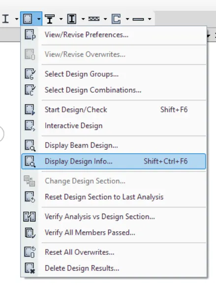
- After this we need to go to the option Concrete frame design at the top of the screen and click on the arrow in the downward direction just as shown in the below image:
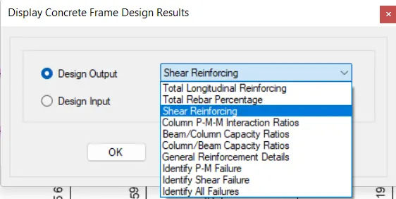
- After this a new dialouge box opens named as Display Concrete Frame Design Results opens,in that dialouge box go to the option Design Output there go to the Shear Reinforcing option and then click on the option OK just as shown in the below given image:
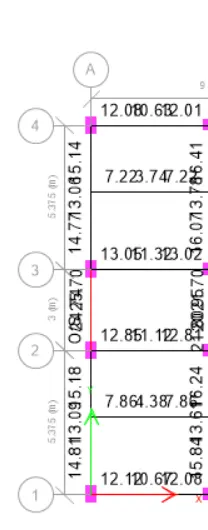
- Longitudinal Reinforcement of Beam at Grid-A from the ETABS (sq.m):
- Below is the screenshoot of the beam at the grid-A from the ETABS software:
- Now we will be doing the calculations for the Reinforcement detailing along Grid A:
- Maximum `Ast`at the bottom support = 1945 sq.m.
- Maximum `Ast`at the bottom middle = 789 sq.m.
- Maximum `Ast`at the top support = 2046 sq.m.
- Maximum `Ast`at the top middle = 511 sq.m.
- So the calculation for the Reinforcement for Grid-A is given below:
- For Top support:
- Total `Ast` required at the top = 2046 sq.m.
So we can provide, 4 bars of 20mm diameter and 4 bars of 16mm diameter.
4 bars of 20mm diameter = 4 X 314 = 1256 sq.m.
4 bars of 16mm diameter = 4 X 201 = 804 sq.m.
And to check if this satisfy the criteria or not, add both the diameter's Ast:
Therefore, Total Ast = 4 bars of 20mm diameter + 4 bars of 16mm diameter
= 1256 + 804
= 2060 sq.m.
Hence this satisfy the above criteria.
- For Bottom support:
- So the total `Ast` required for the bottom support = 1945 sq.m.
So we can provide, 3 bars of 20mm diameter and 5 bars of 16mm diameter.
3 bars of 20mm diameter = 3 X 314 = 942 sq.m.
5 bars of 16mm diameter = 5 X 201 = 1005 sq.m.
And to check if this satisfy the criteria or not, add both the diameter's Ast:
Therefore, Total Ast = 3 bars of 20mm diameter + 5 bars of 16mm diameter
= 942 + 1005.
= 1947 sq.m.
Hence this satisfy the above criteria.
- Shear Details:
- Now we will be checking the shear details.
- So in order to check the shear details first we need to select the column and then right-click on that column.
- And then a new dialouge box opens named as the Concrete Beam Design Information (IS 456:2000) in that option just click the combination and then click on the Details option just as shown in the below image:
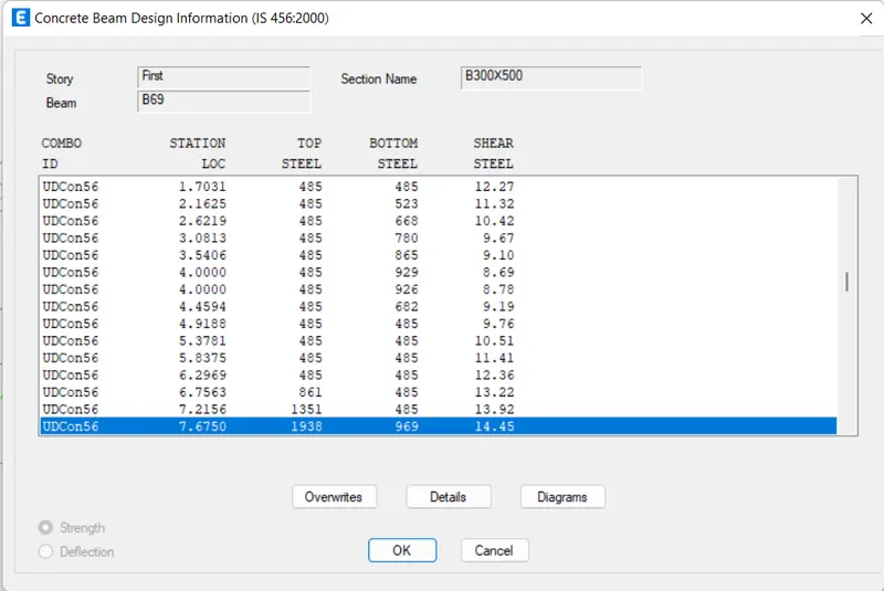
- And then after clicking on the Details option an another dialouge box opens named as Design Details,this dialouge box contains all the information regarding the shear details just as shown in the below given figure:
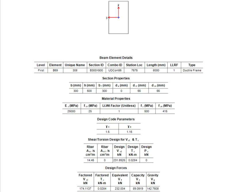
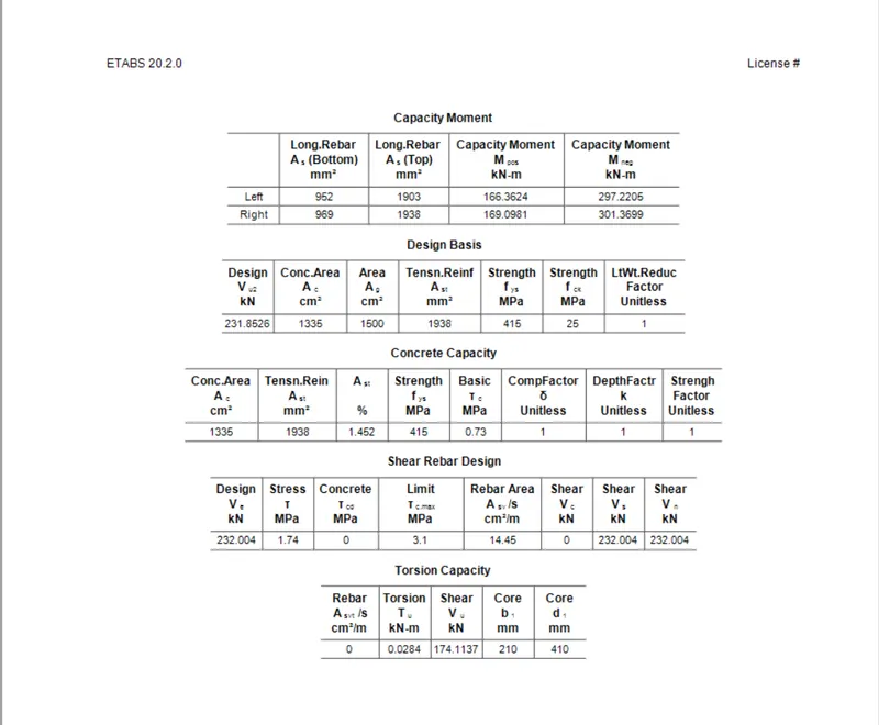
- So according to the clause 6.3.3 it suggest that we should provide spacing till 2d from the face of the column should be 100. And it should not be more than that.
- So here we should be providing the 3 legged stirrups of 10mm diameter with 100mm spacing.
- Shear Reinforcement of Beam at Grid-3 from the ETABS (sq.cm/1000mm):
- Below is the screenshoot of the beam at the grid-A from the ETABS software:

- And now we will be doing the Reinforcement calculations for the Grid 3:
- Maximum `Ast`at the bottom support = 1042 sq.m.
- Maximum `Ast`at the bottom middle = 1501 sq.m.
- Maximum `Ast`at the top support = 1940 sq.m.
- Maximum `Ast`at the top middle = 485 sq.m.
- So the calculation for the Reinforcement is given below:
- For Top support:
- Total `Ast` required at the top = 1940 sq.m.
So we can provide, 3 bars of 20mm diameter and 5 bars of 16mm diameter.
3 bars of 20mm diameter = 3 X 314 = 942 sq.m.
5 bars of 16mm diameter = 5 X 201 = 1005 sq.m.
And to check if this satisfy the criteria or not, add both the diameter's Ast:
Therefore, Total Ast = 3 bars of 20mm diameter + 5 bars of 16mm diameter
= 942 + 1005
= 1947 sq.m.
Hence this satisfy the above criteria.
- For Bottom support:
- So the total `Ast` required for the bottom support = 1501 sq.m.
So we can provide, 3 bars of 20mm diameter and 3 bars of 16mm diameter.
3 bars of 20mm diameter = 3 X 314 = 942 sq.m.
3 bars of 16mm diameter = 3 X 201 = 603 sq.m.
And to check if this satisfy the criteria or not, add both the diameter's Ast:
Therefore, Total Ast = 3 bars of 20mm diameter + 5 bars of 16mm diameter
= 942 + 603.
= 1545 sq.m.
Hence this satisfy the above criteria.
- Shear Details:
- Now we will be checking the shear details.
- So in order to check the shear details first we need to select the column and then right-click on that column.
- And then a new dialouge box opens named as the Concrete Beam Design Information (IS 456:2000) in that option just click the combination and then click on the Details option just as shown in the below image:
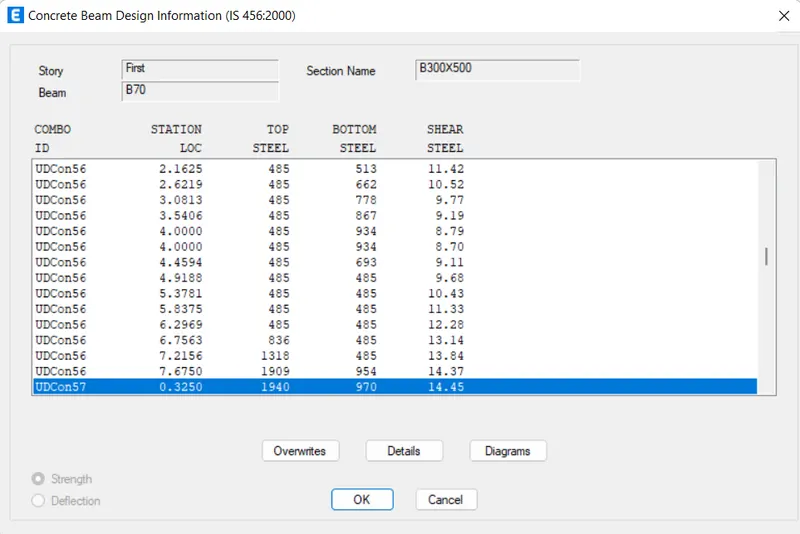
- And then after clicking on the Details option an another dialouge box opens named as Design Details,this dialouge box contains all the information regarding the shear details just as shown in the below given figure:
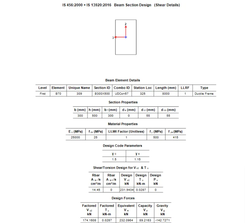
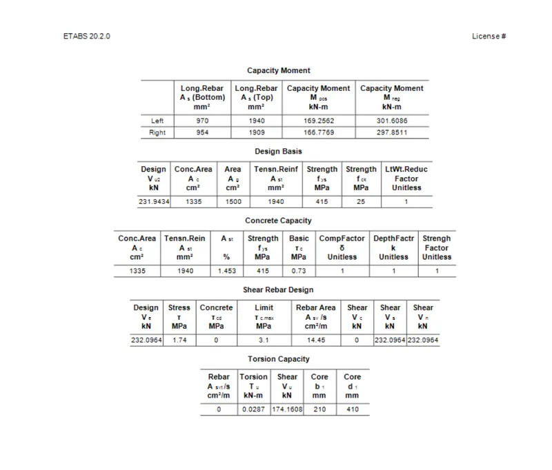
- So according to the clause 6.3.5 of IS 13920:2016, it suggest that we should provide spacing till 2d from the face of the column should be 100. And it should not be more than that. Below is the given image:
- So here we should be providing the 3 legged stirrups of 10mm diameter with 100mm spacing throughout the beam length.
- And we should provide 3 legged stirrups of 8mm diameter with 150mm spacing at the mid-span.
- Check for the Right Sway Shear:
- After this we will be doing the calculations for the Sway shear force to the Right:
- And the formula for Right Sway is mentioned below:
`Vua=Vua^(D+L)-1.4frac{Mu^(As)+Mu^(Bh)}{Lab}`
`Vub=Vub^(D+L)+1.4frac{Mu^(As)+Mu^(Bh)]{Lab}`
Where:
`Mu^(As)=`Support A sagging moment.
`Mu^(Bh)=`Support B hogging moment.
`Vua^(D+L)=`Factored gravity shear force which is not included any lateral force.
`Vub^(D+L)=`Factored gravity shear force which is not included any lateral force.
- Below are the given values from the ETABS model:
- `Vu^(D+L)=92 KN.`
- `Munderset(as)`= 176 KN/m.
- `Munderset(bh)`= 295 KN.
- `Lunderset(ab)`= 4.725 m.
- Now put these above values in the formula:
- `Vua=Vua^(D+L)-1.4frac{Mu^(As)+Mu^(Bh)}{Lab}`
`Vunderset(u,a)`= `92-1.4frac{176+295}{4.725}`
`Vunderset(u,a)`= `92-(1.4xx99.68)`
`Vunderset(u,a)`= `48 KN`
- `Vu,b=Vu,b^(D+L)+1.4frac{Mu^(As)+Mu^(Bh)}{Lab}`
-
`Vunderset(u,b)`= `92+1.4frac{176+295}{4.725}`
`Vunderset(u,b)`= `92+(1.4xx99.68)`
`Vunderset(u,b)`= `231 KN`
Therefore, `Vunderset(u,a)`= `48 KN`
`Vunderset(u,b)`= `231 KN`
- Check for the Left Sway Shear:
- After this we will be doing the calculations for the Sway shear force to the Left:
- And the formula for Left Sway is mentioned below:
`Vua=Vua^(D+L)-1.4frac{Mu^(Ah)+Mu^(Bs)}{Lab}`
`Vub=Vub^(D+L)+1.4frac{Mu^(Ah)+Mu^(Bs)]{Lab}`
Where:
`Mu^(Ah)=`Support A hogging moment`
`Mu^(Bs)=`Support B sagging moment`
`Vua^(D+L)=`Factored gravity shear force which is not included any lateral force.
`Vub^(D+L)=`Factored gravity shear force which is not included any lateral force.
- Below are the given values from the ETABS model:
- `Vu^(D+L)=74 KN.`
- `Munderset(ah)`= 236 KN/m`
- `Munderset(bs)`= 150 KN`
- `Lunderset(ab)`= 4.725 m.
- Now put these above values in the formula:
- `Vua=Vua^(D+L)-1.4frac{Mu^(Ah)+Mu^(Bs)}{Lab}`
`Vunderset(u,a)`= `74-1.4frac{236+150}{4.725}`
`Vunderset(u,a)`= `74-(1.4xx81.69)`
`Vunderset(u,a)`= `40 KN`
- `Vu,b=Vu,b^(D+L)+1.4frac{Mu^(Ah)+Mu^(Bs)}{Lab}`
-
`Vunderset(u,b)`= `74+1.4frac{236+150}{4.725}`
`Vunderset(u,b)`= `74+(1.4xx81.69)`
`Vunderset(u,b)`= `189 KN`
Therefore, `Vunderset(u,a)`= `40 KN`
`Vunderset(u,b)`= `189 KN`
- Existing Shear Capacity in beam:
- And now we will be calculating the existing shear capacity in beam by the below given formula as per IS 456:2000:
`Vunderset(us)`= `frac{0.87fyAsvd}{sv}`
And below is the values given:
- fy = 415 N/sq.m.
- Asv = 151 sq.m.
- Spacing = 150 mm.
- d = 450 mm.
- Now put the above values in the given equation:
`Vunderset(us)`= `frac{0.87fyAsvd}{sv}`
`Vunderset(us)`= `frac{0.87xx415xx151xx450}{100}`
`Vunderset(us)`= 246 KN.
- Hence the Shear capacity which is 246 KN is larger than the Shear sway which is 231 KN. So it means that it is safe.
- Provide reasons for failure of the middle span along grid A. What are the possible ways this issue can be resolved?
Answer: Reasons of failure:
- So the main reason for the failure of the middle span along the grid A,is that the stress is being beyond the allowable value. And this is the reason why it is not possible to calculate the reinforcement.
- And this may be because of the higher shear force which is acting on that beam.
- Here the torsion is minimum but the stress increased.
- Suggestions:
- There are two possible ways to stop the failure that is either increase the loadings or decrease the loadings.
- And we know that the shear capacity of the concrete varies w.r.t. the grade of concrete. So instead of using the M30 grade of concrete for the entire beam, use higher grade of concrete, only then we can increase the shear capacity of the beam.And we can make it pass it in the shear stress design.
- Calculate value of the maximum shear force in any one of the spans in both the continuous beams, as per clause 6.3.3 (b) in IS 13920 – 2016. Also, confirm these values from shear force demand calculated by ETABS.Please note that if longitudinal reinforcement provided is more than required (as per ETABS results), the shear force demand will vary from what is provided by ETABS.
Answer. As we already calculated the value of the shear stress in the above calculations according to the IS 13920:2016 clause 6.3.3(b). And according to the calculations that we have already done before for the right and the left shear sway,both the values are within the limit. So it is not necessary to re-design the beam.