Radial Engine Assembly : Week 4 Challenge
RADIAL ENGINE ASSEMBLY
The Radial Engine assembly consists of 10 Parts which are first created as part files and later on assembled in an assembly file using different constraints.
PISTON:
The piston was created using different features like shaft, groove, pad, pocket, mirror.
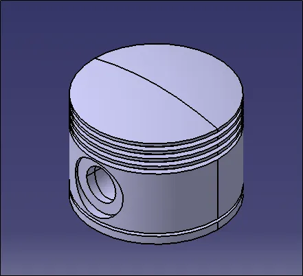
Fig 1. Piston Isometric View
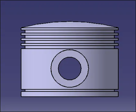
Fig 2. Piston Front View
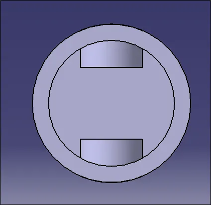
Fig 3. Piston Bottom View
MASTER ROD:
The Master Rod was created using different features like pad, pocket, mirror.
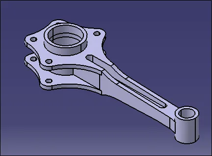
Fig 4. Master Rod Isometric View
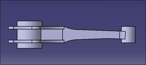
Fig 5. Master Rod Front View
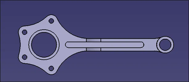
Fig 6. Master Rod Top View
PISTON RING:
The Piston Ring was created using feature Pad.
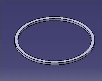
Fig 7. Piston Ring Isometric View
PISTON PIN:
The Piston Pin was created using feature Pad.
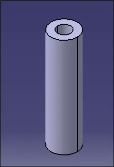
Fig 8. Piston Pin Isometric View
PISTON PIN PLUG:
The Piston Pin Plug was created using different features like Pad , Edge Fillet.
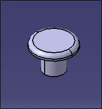
Fig 9. Piston Plug Isometric View
MASTER ROD BEARING:
The Master Rod Bearing was created using feature Pad.
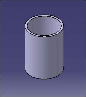
Fig 10. Master Rod Bearing
ARTICULATE ROD:
The Articulate Rod was created using different features like Pad , Pocket.
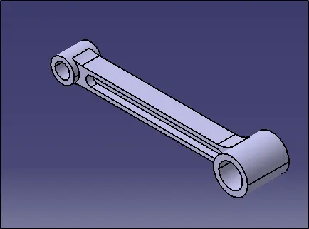
Fig 11. Articulate Rod Isometric View
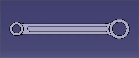
Fig 12. Articulate Rod Top View
LINK PIN:
The Link Pin was created using feature Pad.
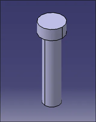
Fig 13. Link Pin Isometric View
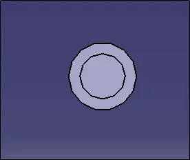
Fig 14. Link Pin Bottom View
ROD BUSH LOWER:
The Rod Bush Lower was created using feature Pad.
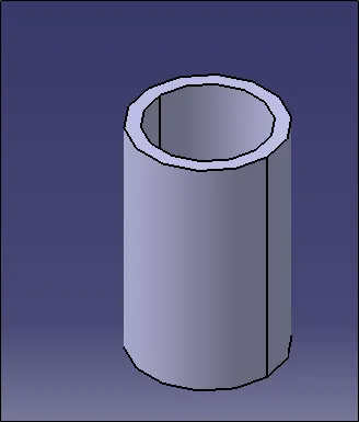
Fig 15. Rod Bush Lower Isometric View
ROD BUSH UPPER:
The Rod Bush Upper was created using feature Pad.
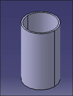
Fig 16. Rod Bush Upper Isometric View
ASSEMBLY:
After creating all the different part files they are assembled together in an assembly file by using different constraints like offset constraint, surface contact , coincidence constraint and angle constraint.
The assembly views are:
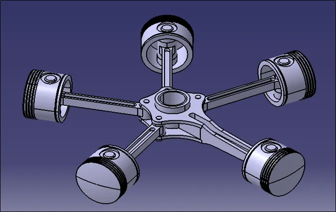
Fig 17. Assembly Isometric View
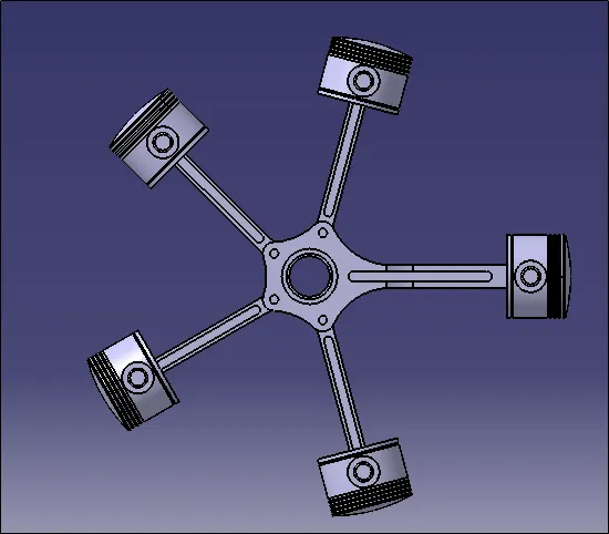
Fig 18. Assembly Top View
*****