Radar Mast & Final Assembly of Yacht
Modeling and rendering of Sunseeker Predator Yacht using Solidworks
Objective :
The main objective of this project is
- To create individual part models of Yacht
- To create Assembly of a Yacht
- To create the rendering images using the Photo view 360 tools.
- To create real-time rendering images with Solidworks Visualize by using required appearances and environments
Introduction :
SolidWorks is a 3D mechanical CAD program that suddenly spikes in demand for MicrosoftWindows which was created by SolidWorks partnership, headquartered in the USA, an auxiliary of Dassault Systemes. SolidWorks furnishes engineers, designers, and other imaginative experts with the devices they need to plan the world's most prominent items. SolidWorks gives a full scope of coordinated displaying, reproduction, perception, correspondence, and approval devices that item planners need to grow better items quicker and at a lower cost. Also, its special capacities empower the mechanical architect to focus on the item plan.
A yacht is a sailor power vessel used for pleasure, cruising, or racing. There is no standard definition, so the term applies to such vessels that have a cabin with amenities that accommodate overnight use. To be termed a yacht, as opposed to a boat, such a pleasure vessel is likely to be at least 33 feet (10 m) in length and may have been judged to have good aesthetic qualities
Design Flow Chart :
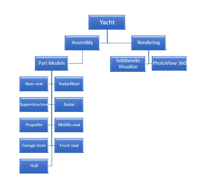
Important Procedures used in modeling all individual parts
- The Common Template of Metric values(MMGS - millimeter, gram, second) is used to model all parts.
- All sketch drawings will be fully defined in all the part models.
- All part models are defined with appropriate material, appearance, and color.
- Solidworks version used for modeling: 2019-20.
2D Sketch: A 2D drawing view consists of two-dimensional elements. A 2D drawing view allows you to quickly create or modify a drawing view without making changes to a part or assembly document.
3D Sketch: A 3D sketch is a sketch that is not limited to a single plane. You can have a 3D sketch that is planar, but it has the option of not being on the plane. While a 2D sketch is limited to the single plane that it was started on.
Extruded Boss/Base: Extrudes a sketch or selected sketch contours in one or two directions to create a solid feature.
That means, if you have a closed contour sketch drawing, then you can materialize that contour and convert it into a 3D model.
Revolved Boss/Base: Revolved Boss/Base is a Solidworks feature tool that is used to create a solid 3D model around an axis. You can revolve the sketch around an axis to add materials to it.
Swept Boss/Base: Swept Boss/Base is one of the useful features which help to sweep a closed profile through an open or closed path.
Lofted Boss/Base: Loft Boss/Base mainly helps to add materials between two or more profiles with ease. The profile should be closed and you can use it for a profile different or similar in shape.
Boundary Boss/Base: Boundary Boss/Base is a tool used to create features by adding materials in two directions. That means you can add materials between two profiles between two Boundaries.
Extruded Cut: Extrude cut is another cool feature that helps to remove materials from the 3D model. It is just opposite to extrude boss/base features because it cuts a sketch profile while extruding.
You can cut in both directions and mainly used for creating holes, channels, slots, etc.
Revolved Cut: Revolved cut feature is one of the very useful Solidworks feature tools, which helps to remove materials from 3D models possessing axis symmetry.
Revolved cut removes materials by revolving a closed profile along an axis.
Swept Cut: Solidworks swept cut is mainly used to cut a solid model or part by sweeping a completely closed profile along an open or closed path. To use swept cuts, you should need a closed profile and open or closed path, which may be a line, helix, and circle, rectangular or arc, etc.
Projected curve: Projected curve is a type of curve available in Solidworks which is used to create/project a curve onto the face of the model or to create a 3D curve in Solidworks.
We can also create a 3D by creating two different sketches in two different sketches in two different planes, the intersection between the two sketches is converted as a Projected curve
Linear Pattern: Linear pattern feature tool is used to create patterns of closed profiles in extruded parts. For linear patterning, there is a parent pattern (base pattern) which is used to create the array of patterns in one or two dimensions.
Fillet: A fillet is a feature tool that is used for rounding of interior or external face along with one or more edges of your design. The radius of fillet or round radius is deciding the amount of filleting in the design part.
Chamfer: The chamfer tool is one of the useful tools, which helps to cut (like the 45-degree angle with the normal surface) or make edges or corners (vertex) of a 3D model straight.
Shell: Solidworks shell tool is mainly used for the shelling process, in which the material is removed from the inner body of the model by keeping a small thickness and results in a hollow model.
Using this tool, you can make either a completely closed hollowed model or one face opened type.
Mirror: Mirror feature tool is used to create a copy of your sketch/model on its opposite side. If you have to make the same copy or mirror image, on the other hand, the Solidworks Mirror function helps to do it instantly.
Reference Plane : The planes which are used other than the default Top, Right, and Front Planes are known as reference plane.
Modeling of Blueprint :
Blueprint: A blueprint is a reproduction of a technical drawing or engineering drawing using a contact print process on light-sensitive sheets. It was widely used for over a century for the reproduction of specification drawings used in construction and industry.
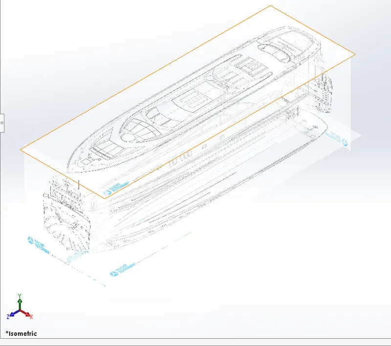
Features used for Modeling of Blueprint
- 2D Sketch
- Sketch Picture
Modeling of Front Seat:
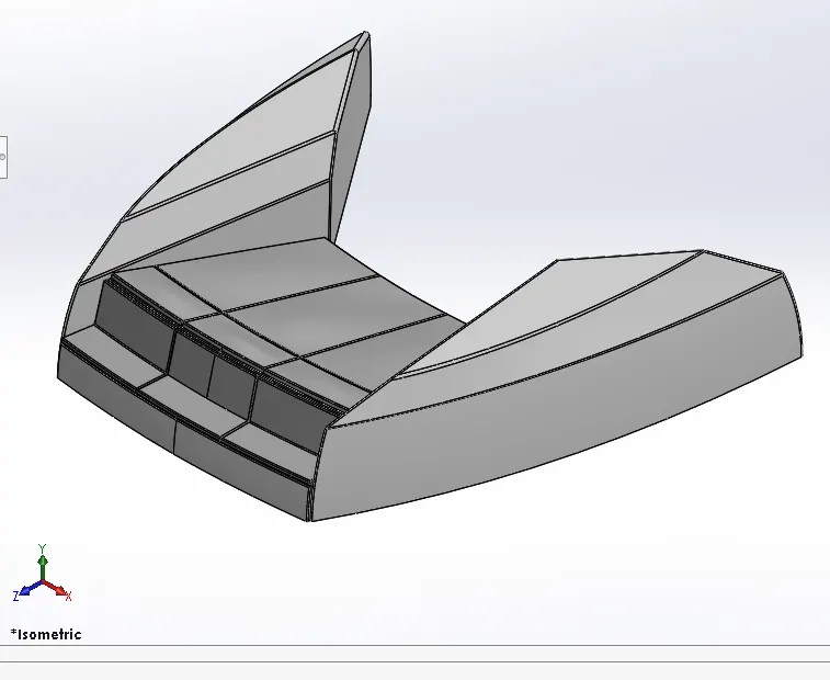
Features used for Modeling of Front Seat
- 2D sketch
- Reference Plane
- Surface - Swept Boss/Base
- Surface - Extruded Boss/Base
- Trim
- Surface Fill
- Surface - Loft Boss/Base
- Knit
- Chamfer
- Revolve Boss/Base
- Extruded Cut
- Fillet
- Mirror
- Dome
Dome: Dome is a hollow half of a sphere. Domes are one of the most familiar features in architecture, frequently used for government and religious buildings. A dome is a curved formation or structure. It is shaped like half of a sphere
Modeling of Garage Door :
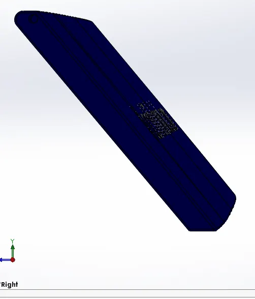
Features used for Garage Door :
- 2D sketch
- Extruded Cut
- Shell
- Fillet
- Mirror
- Reference Plane
Reference Plane : The planes which are used other than the default Top, Right, and Front Planes are known as reference plane.
Modeling of Hull :
Hull: A hull is the watertight body of a ship, boat, or flying boat. The hull may open at the top (such as a dinghy), or it may be fully or partially covered with a deck. Atop the deck may be a deckhouse and other superstructures, such as a funnel, derrick, or mast.
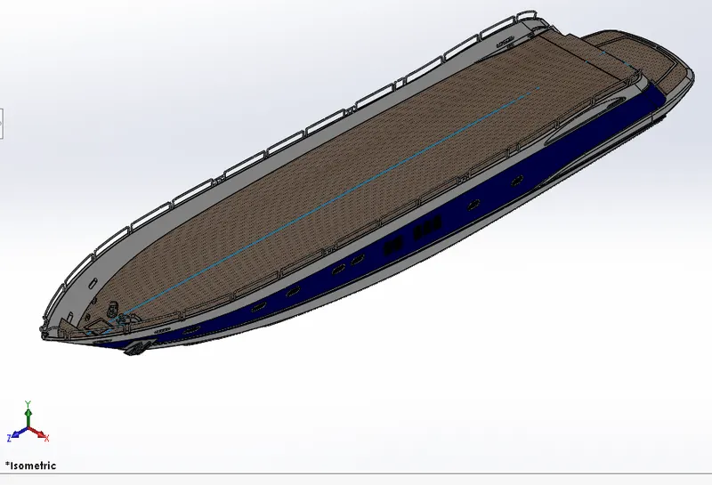
Features used for Modeling of Hull :
- BluePrints
- 2D sketch
- Projected Curve
- Surface-Lofted Boss/Base
- Surface Trim
- Surface-Extruded Boss/Base
- Surface Knit
- Surface Fill
- Shell
- Extruded Boss/Base
- Extruded Cut
- Fillet
- Chamfer
- Reference Plane
- Swept Boss/Base
- 3D sketch
- Revolved Boss/Base
- Dome
- Helix/Spiral tool
- Linear Pattern
- Combine
- Mirror
- Extruded Cut-Thin
- Split Line
Knit: Knit Surface tool is used to combine two or more faces and surfaces into one.
Dome: Dome is a hollow half of a sphere. Domes are one of the most familiar features in architecture, frequently used for government and religious buildings. A dome is a curved formation or structure. It is shaped like half of a sphere
Split Line: The Split Line. the tool projects an entity (sketch, solid, surface, face, plane, or surface spline) to surfaces, or curved or planar faces. It divides a selected face into multiple separate faces. You can split curves on multiple bodies with one command.
Helix/Spiral tool: The Helix and Spiral tool can be cleverly used to generate 3D curves which can be then used as a sweep path. Ideal for creating springs!
Surface Fill: The Filled Surface feature constructs a surface patch with any number of sides, within a boundary defined by existing model edges, sketches, or curves, including composite curves. You can use this feature to construct a surface to fill a gap in a model.
Modeling of Middle Seat:
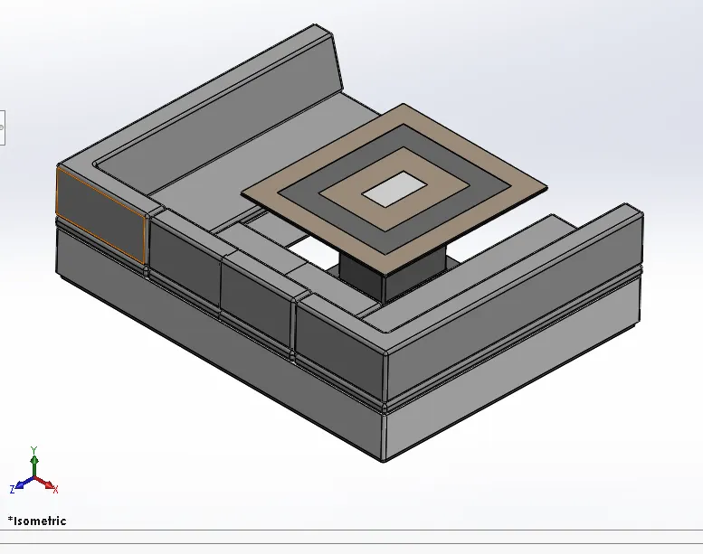
Features used for Modeling of Middle Seat:
- 2D sketch
- BluePrints
- Extruded Boss/Base
- Reference Plane
- Chamfer
- Fillet
- Mirror
- Extruded Cut
Fillet: A fillet is a feature tool that is used for rounding of interior or external face along with one or more edges of your design. The radius of fillet or round radius is deciding the amount of filleting in the design part.
Modeling of Propeller :
Propeller: The purpose of the propeller is to provide a method of propulsion so the aircraft is able to move forward through the air. The propeller itself consists of two or more blades connected together by a central hub that attaches the blades to the engine shaft.
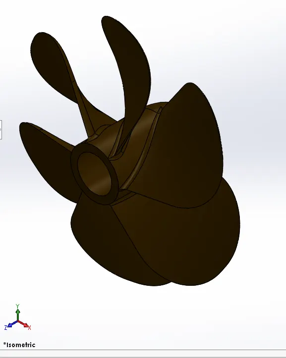
Features used for Modeling of Propeller :
- 2D sketch
- Revolved Boss/Base
- Reference Plane
- Lofted Boss/Base
- Fillet
- Extruded Cut
- Fillet
- Circular Pattern
Circular Pattern: Circular pattern feature tool is the same as the Linear pattern, used to create patterns of closed profile in extruded parts.
But In circular Patterns, Patterns are created in reference with 360 degrees or circular.
Fillet: A fillet is a feature tool that is used for rounding of interior or external face along with one or more edges of your design. The radius of fillet or round radius is deciding the amount of filleting in the design part.
Modeling of Radar :
Radar: A device or system consisting usually of a synchronized radio transmitter and receiver that emits radio waves and processes their reflections for display and is used especially for detecting and locating objects or surface features.
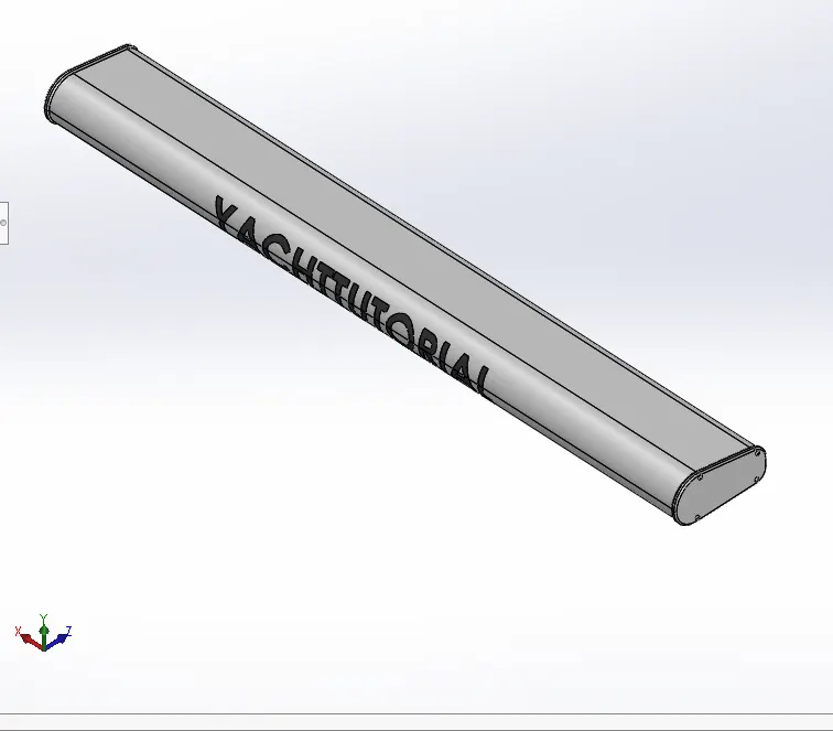
Features used for Modeling of Radar :
- 2D sketch
- Extruded Boss/Base
- Fillet
- Extruded Cut
- Sketch Pattern
- Mirror
- Split Line
Split Line: The Split Line. the tool projects an entity (sketch, solid, surface, face, plane, or surface spline) to surfaces, or curved or planar faces. It divides a selected face into multiple separate faces. You can split curves on multiple bodies with one command.
Modeling of Rear Seat :
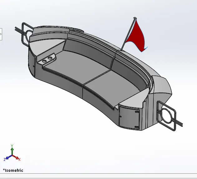
Features used for Modeling of Rear Seat :
- 2D sketch
- Blueprints
- Reference Plane
- Surface-Swept Boss/Base
- Surface Offset
- Surface Trim
- Ruled surface
- Surface Knit
- Reference Plane
- Surface Extend
- Surface- Extruded Boss/Base
- Surface Lofted Boss/Base
- Extruded Cut
- Chamfer
- Fillet
- Mirror
- Revolved Boss/Base
Surface Extend: You can extend a surface by selecting an edge, multiple edges, or a face. Under Edges/Faces to Extend, select one or more edges or faces in the graphics area for Selected Face/Edges., For edges, the surface extends along the plane of the edge.
Fillet: A fillet is a feature tool that is used for rounding of interior or external face along with one or more edges of your design. The radius of fillet or round radius is deciding the amount of filleting in the design part.
Modeling of RadarMast :
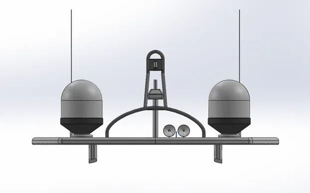
Features used for Modeling of RadarMast :
- BluePrints
- 2D sketch
- 3D sketch
- Reference Plane
- Extruded Boss/Base
- Fillet
- Revolved Boss/Base
- Projected Curve
- Swept Boss/Base
- Chamfer
- Dome
- Extruded Cut
- Shell
- Mirror
Modeling of Superstructure :
Superstructure: A superstructure is an extended construction of any building or platform that rises above the rest of the building or platform in a distinct manner. The size of the superstructure has a great influence on the mobility of the vessels. They are designed in a manner so that they add value and hinder the speed and mobility in the least. The superstructure is mostly designed in fashion as well.
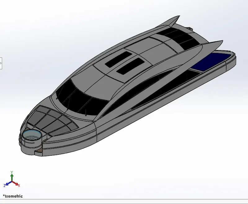
Features used for Modeling of Superstructure :
- BluePrints
- 2D sketch
- 3D sketch
- Projected Curve
- Surface-Lofted Boss/Base
- Surface Trim
- Surface-Extruded Boss/Base
- Surface Knit
- Surface Fill
- Shell
- Extruded Boss/Base
- Extruded Cut
- Fillet
- Chamfer
- Reference Plane
- Swept Boss/Base
- 3D sketch
- Revolved Boss/Base
- Dome
- Linear Pattern
- Surface Knit
- Surface Fill
- Combine
- Mirror
- Extruded Cut-Thin
- Split Line
- Fillet
Dome: Dome is a hollow half of a sphere. Domes are one of the most familiar features in architecture, frequently used for government and religious buildings. A dome is a curved formation or structure. It is shaped like half of a sphere
Split Line: The Split Line. the tool projects an entity (sketch, solid, surface, face, plane, or surface spline) to surfaces, or curved or planar faces. It divides a selected face into multiple separate faces. You can split curves on multiple bodies with one command.
Surface Fill: The Filled Surface feature constructs a surface patch with any number of sides, within a boundary defined by existing model edges, sketches, or curves,
Knit: Knit Surface tool is used to combine two or more faces and surfaces into one.
Surface Extend: You can extend a surface by selecting an edge, multiple edges, or a face. Under Edges/Faces to Extend, select one or more edges or faces in the graphics area for Selected Face/Edges., For edges, the surface extends along the plane of the edge.
3D Sketch: A 3D sketch is a sketch that is not limited to a single plane. You can have a 3D sketch that is planar, but it has the option of not being on the plane. While a 2D sketch is limited to the single plane that it was started on.
Fillet: A fillet is a feature tool that is used for rounding of interior or external face along with one or more edges of your design. The radius of fillet or round radius is deciding the amount of filleting in the design part.
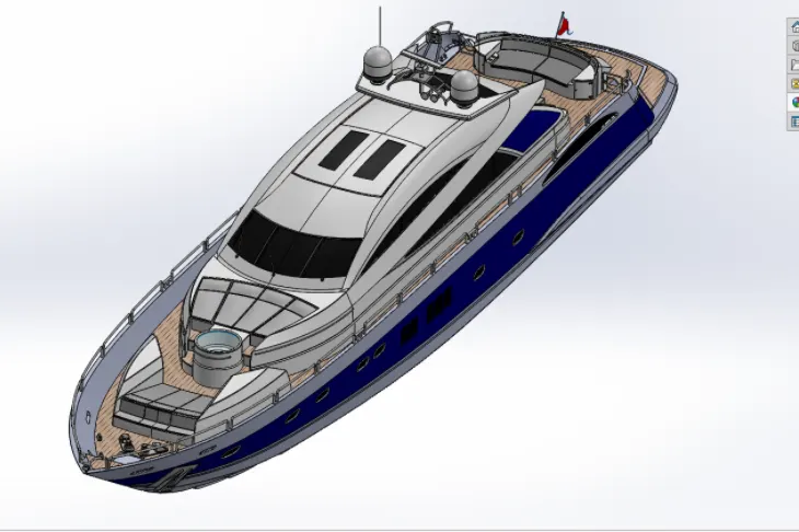
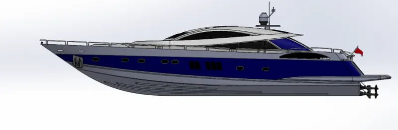
Assembly Of Yacht :
Adding a component to an assembly creates a link between the assembly and the component. When SOLIDWORKS opens the assembly, it finds the component file to show it in the assembly. Changes in the component are automatically reflected in the assembly.
You can build complex assemblies consisting of many components, which can be parts or other assemblies, called subassemblies. For most operations, the behavior of components is the same for both types.
Design Methods (Bottom-up and Top-down Design)
You can create assemblies using bottom-up design, top-down design, or a combination of both methods.
- Bottom-up design: Bottom-up design is the traditional method. Your first design and model parts, then insert them into an assembly and use mates to position the parts. To change the parts, you must edit them individually. These changes are then seen in the assembly.
- Top-down Design: In Top-down design, parts' shapes, sizes, and locations can be designed in the assembly.
For example, You can model a motor bracket so it is always the correct size to hold a motor, even if you move the motor. Solidworks automatically resizes the motor bracket.
This capability is particularly helpful for parts like brackets, fixtures, and housings, whose purpose is largely to hold other parts in their correct positions.
Important Feature of Assembly
Mate: Mates create geometric relationships between assembly components. As you add mates, you define the allowable directions of linear or rotational motion of the components. You can move a component within its degrees of freedom, visualizing the assembly's behavior.
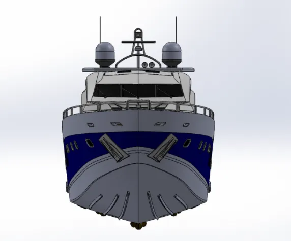
Rendering with PhotoView 360
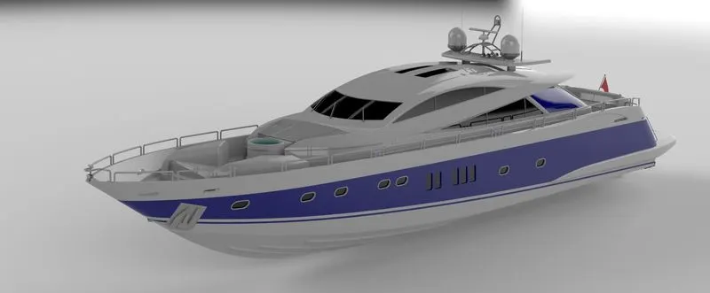
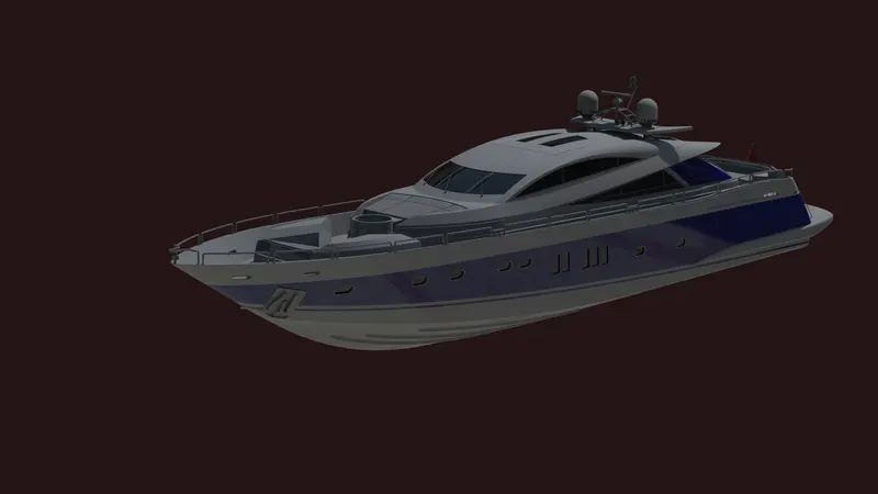
PhotoView 360 is a Solidworks add-in that produces photo-realistic renderings of Solidworks models. The rendered image incorporates the appearances, lighting, scene, and decals included with the model. PhotoView 360 is available with Solidworks Professional or Solidworks Premium.
Rendering with Solidworks Visualize :
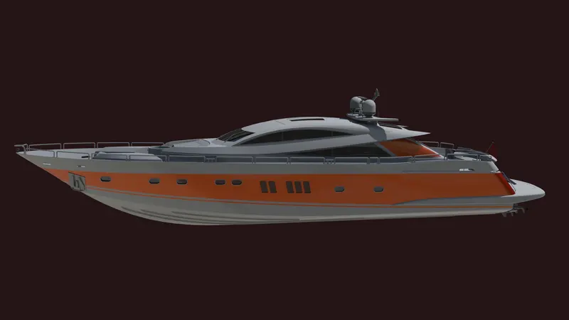
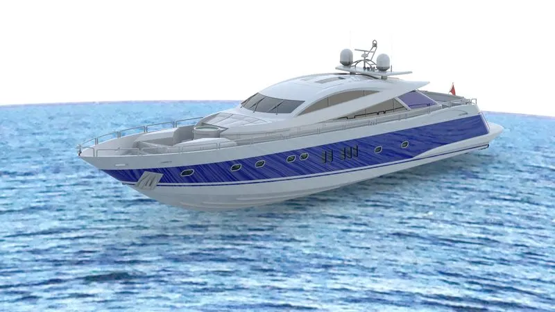
The key benefits of SOLIDWORKS Visualize include:
- Improve internal design, engineering, and sales reviews to help make more educated final decisions
- Drastically reduce the cost and number of physical prototypes, helping to arrive at final design decisions much more efficiently
- Deliver photo-quality imagery and content to marketing much earlier to help promote the newest products via the web and printing
- Added time savings allow for more design time, which results in an overall better final product
- Simple, intuitive interface with a minimal learning curve which helps bring better products to the market faster
Conclusion :
- The parts of the Sunseeker Predator Yacht were modeled.
- The Yacht Assembly was created successfully.
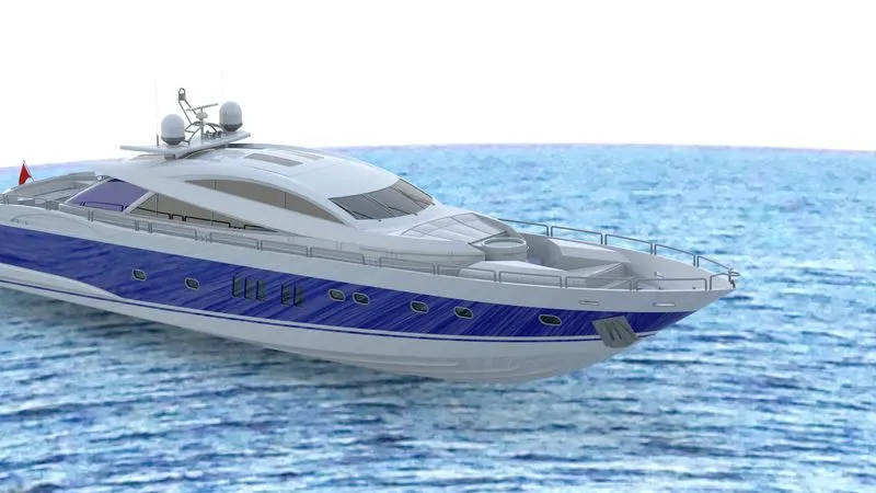
- The Yacht images are rendered with PhotoView 360 and Solidworks Visualize