Advanced Sheet Metal Design Using NX Cad Challenge_5_Odd Shaped Enclosure
Advanced Sheet Metal Design Using NX Cad Challenge_5_Odd Shaped Enclosure
Objective :
The main objective of this project is
- To create sheet metal modeling of the Odd Shaped Enclosure using NX Cad
- To learn about the sheet metal modeling features and applications
Introduction :
Sheet metal is metal formed by an industrial process into thin, flat pieces. Sheet metal is one of the fundamental forms used in metalworking, and it can be cut and bent into a variety of shapes. Countless everyday objects are fabricated from sheet metal.
Sheet metal is used in automobile and truck (lorry) bodies, airplane fuselages and wings, medical tables, roofs for buildings (architecture), and many other applications. Sheet metal of iron and other materials with high magnetic permeability, also known as laminated steel cores, has applications in transformers and electric machines
Design methodology :
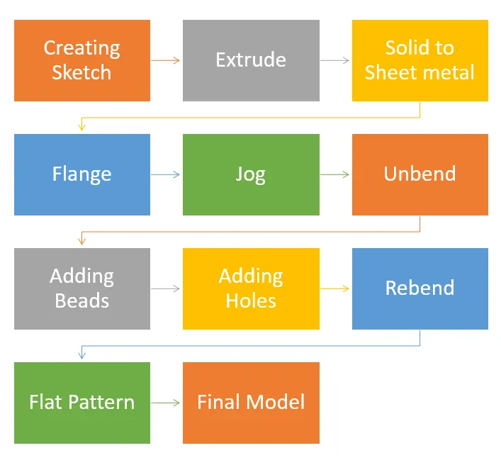
Description :
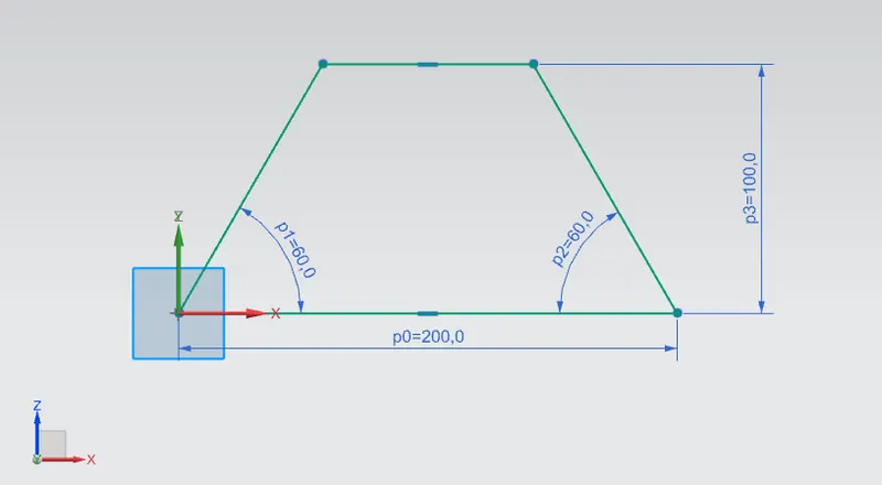
Step 1: Creating a sketch for solid body
An XZ plane is selected to draw the required sketch to form a solid body. The sketch draws are shown in the below figure.
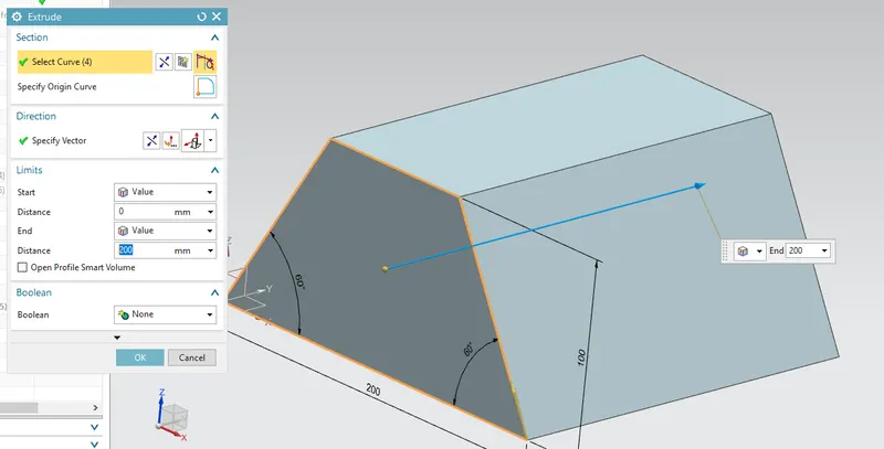
Step 2: Creating a solid using Extrude command.
Extrude is defined as the process of creating a feature from a sketch by adding the material along the direction normal to the sketch or any other specified direction.
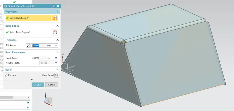
Step 3: Creating Sheet metal from a solid
To create a Sheet metal from a solid body, select the command.
To activate command - Click on command on (When sheet metal application activated.) “ Home => Basic Group => Convert Drop Down => Convert to Sheet Metal”.
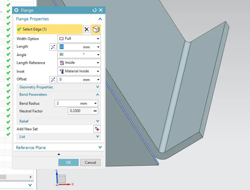
Step 4: Adding a flange
A flange feature consists of a face and bends connected to an existing face along a straight edge. To add a flange feature, you select one or more edges and specify the size and position of the material added.
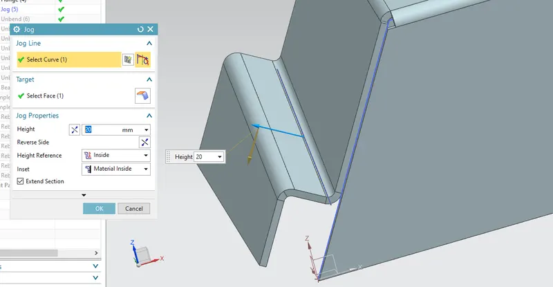
Step 5: Adding Jog.
The Jog tool adds material to a sheet metal part by creating two bends from a sketched line. Some additional items to note about the Jog tool: The sketch must contain only one line. The line does not need to be horizontal or vertical. The bend line does not have to be the exact length of the faces you are bending.
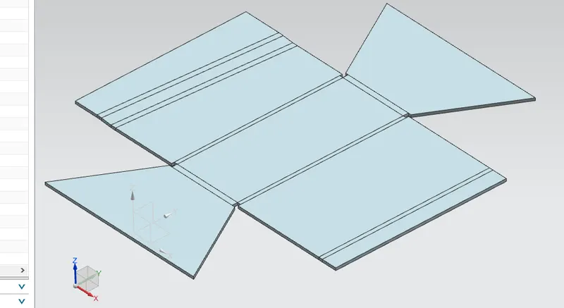
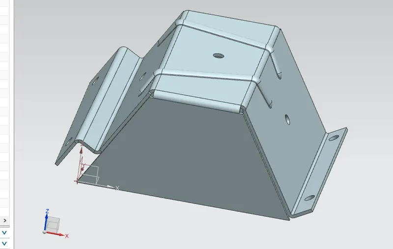
Step 6: Unbend to add more features like holes, beads, etc
Unbend - To flatten a sheet metal feature.
Basically, this feature is used, when the workflow needs to add more features like beads, dimples, holes and more.
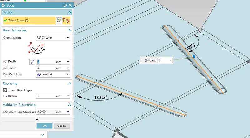
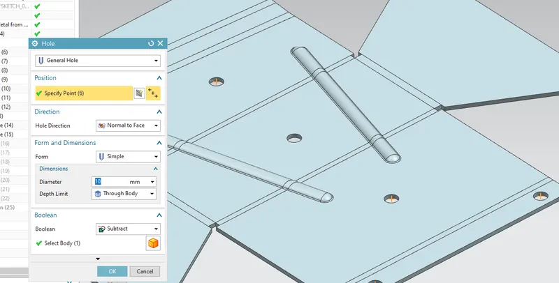
Step 7: Adding Beads and Holes to the model.
Beads are elongated recesses that are stamped into the sheet metal parts to increase the stiffness. To maximize this effect, the length and stamping depth of the bead must be adapted to the size and thickness of the workpiece.
Beading is one of the common bending operations which are used to form beads at the end of the sheets. In beading, the periphery of the sheet metal is bent into the cavity of the die as shown in the following figure.
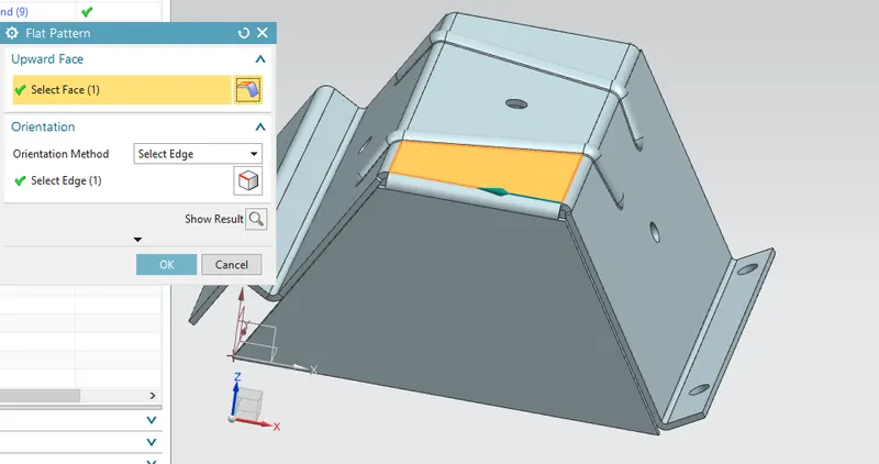
Step 8: Rebend the model and creating a flat pattern.
Use a flat pattern, which is the shape of the sheet metal part before it is formed, to create drawings for manufacturing. Flat patterns show bend lines, bend zones, punch locations, and the shape of the entire part with all bends flattened and bend factors considered.
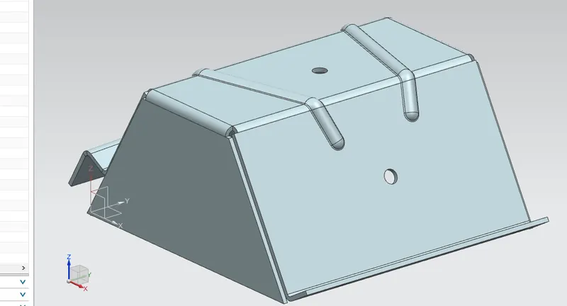
Final Model Views
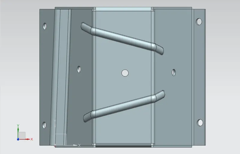
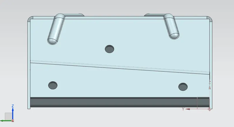
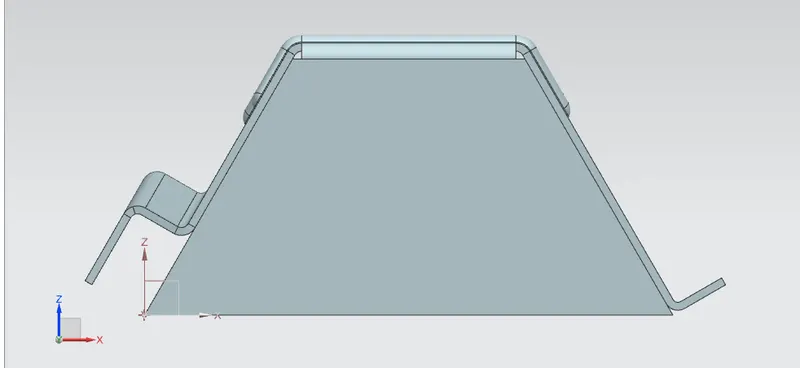
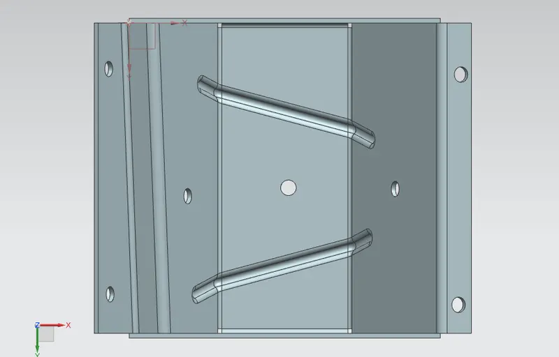
Drafting
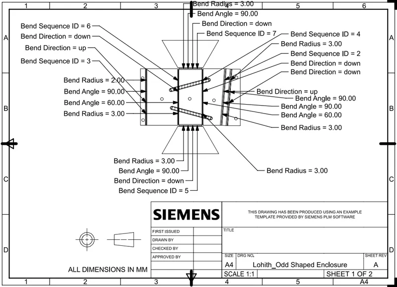
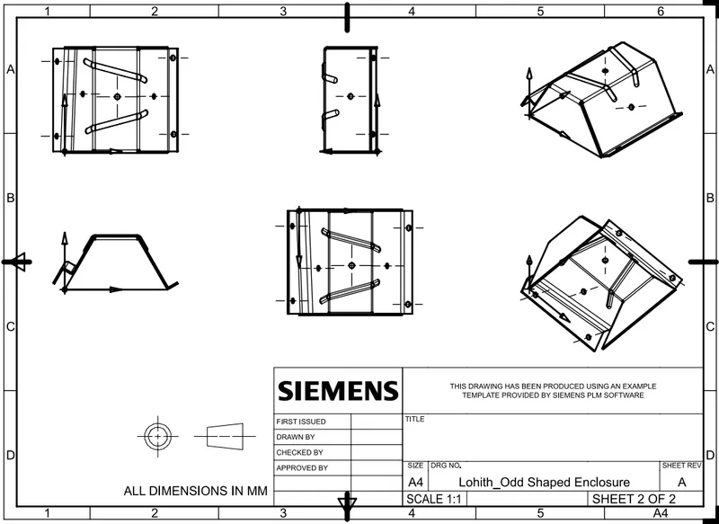
Drafting is a vital tool that allows users to add to their work instructions, hold associativity, and create full prints of tooling and fixturing. New capabilities in NX 12 allow for the jump to drafting from manufacturing while in previous versions of NX, you could only jump to drafting from modeling or assembly.
Conclusion
- Sheet metal modeling of the Odd Shaped Enclosure is successfully created.
- Understood the NX Cad sheet metal features and its application.