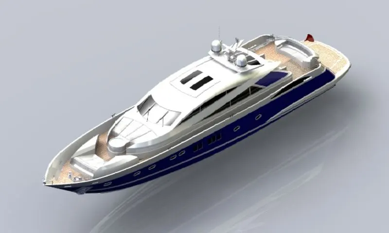
Radar Mast & Final Assembly of Yacht
1. Radar Master
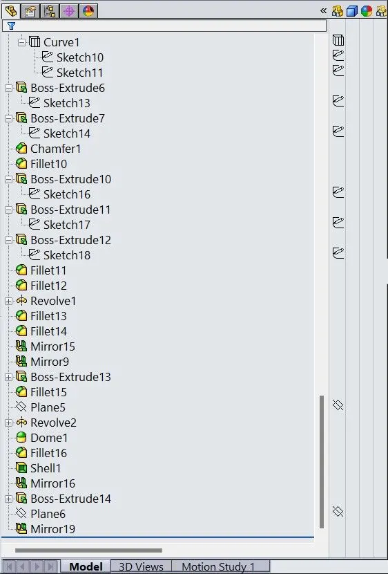
a. Feature Tree.
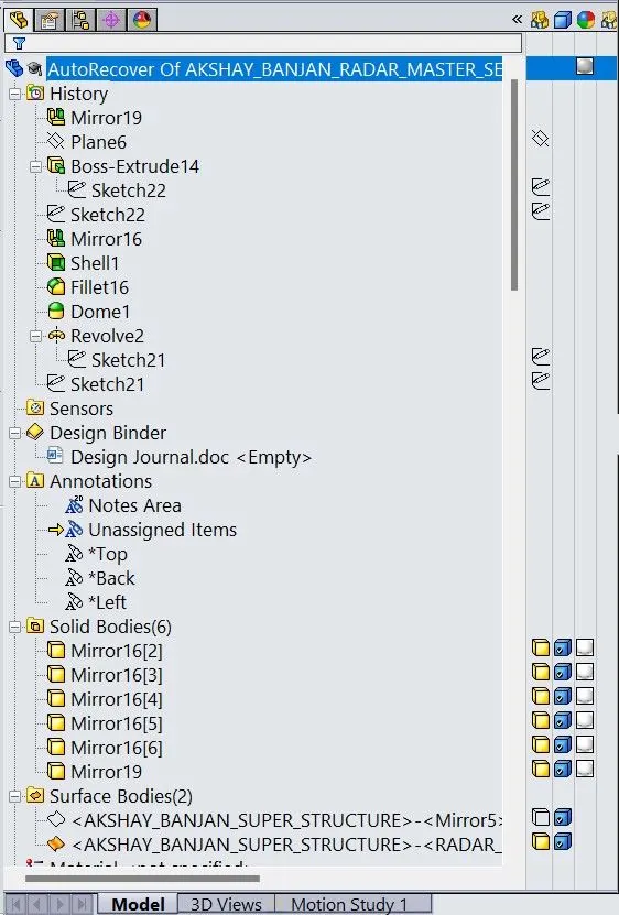
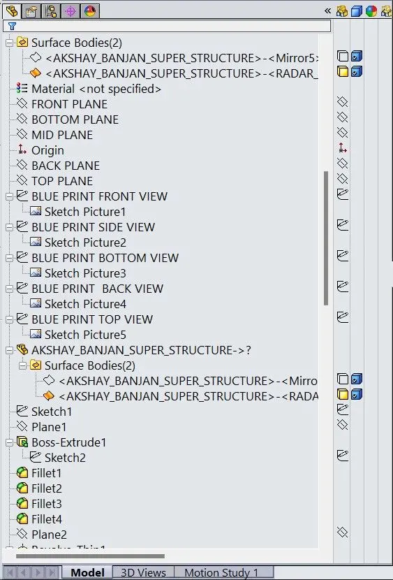
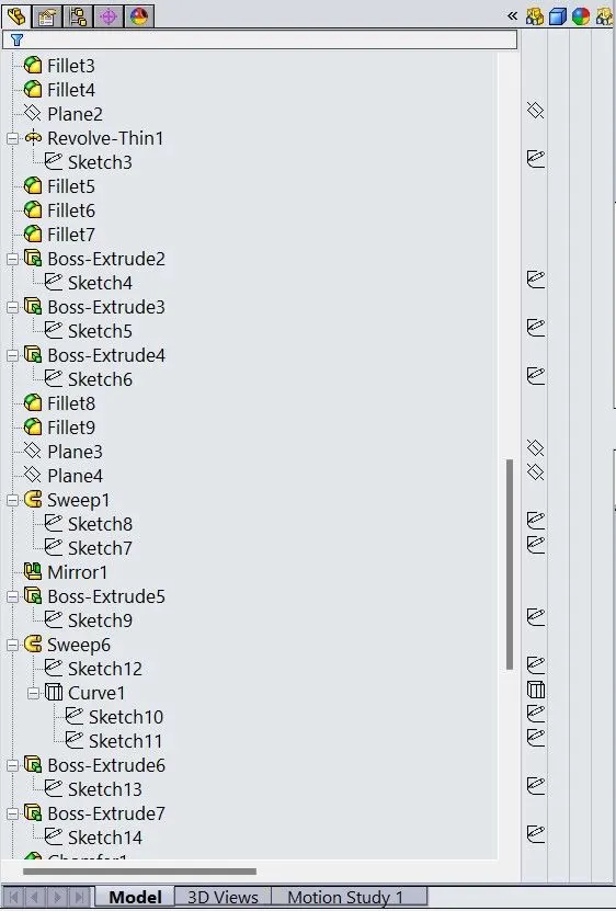
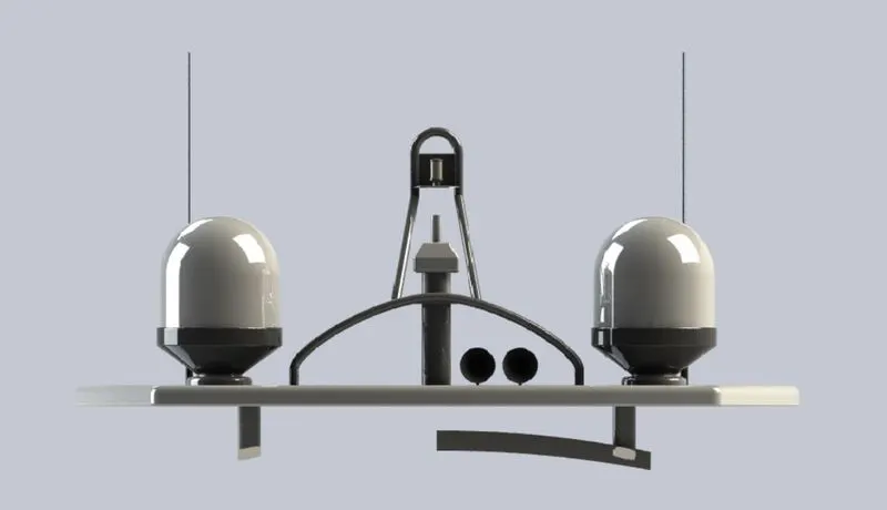
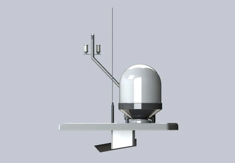
Front View
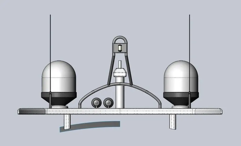
Back View
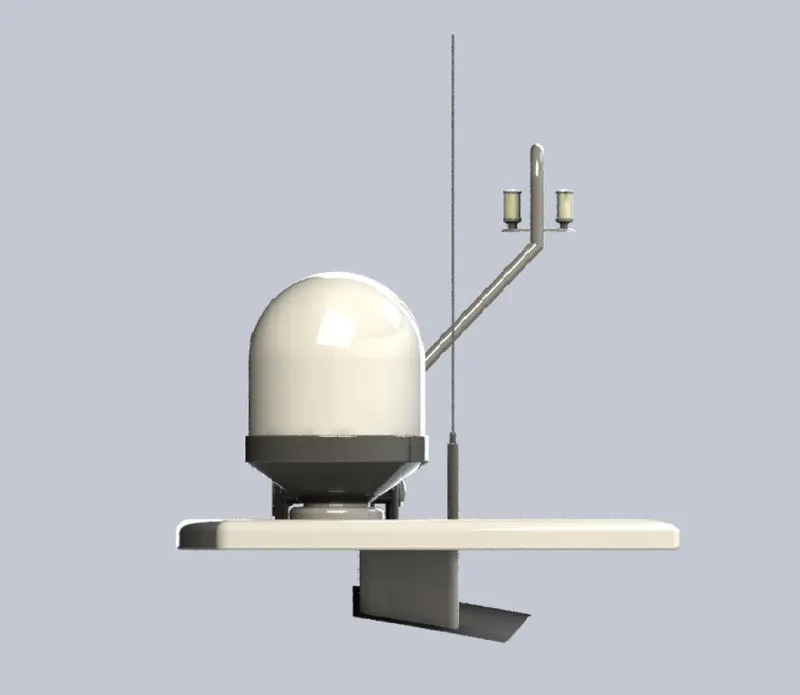
Right View
Left View
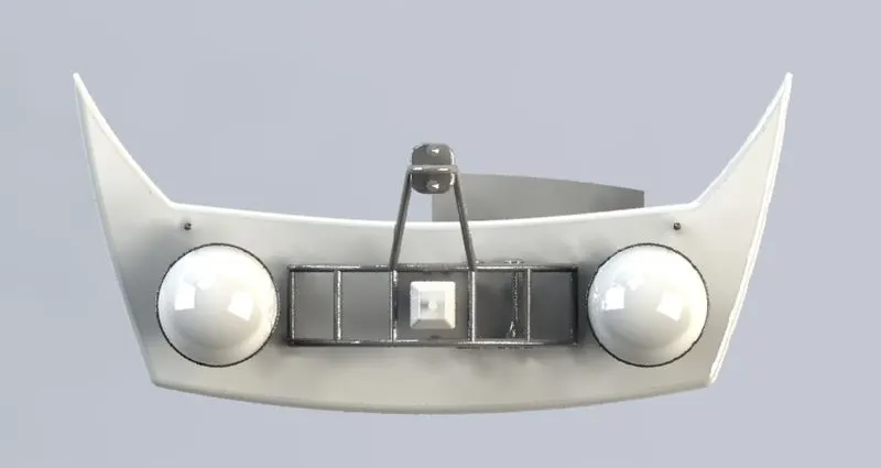
Top View
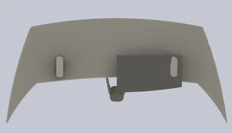
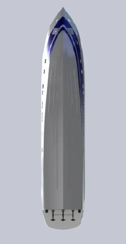
Bottom View
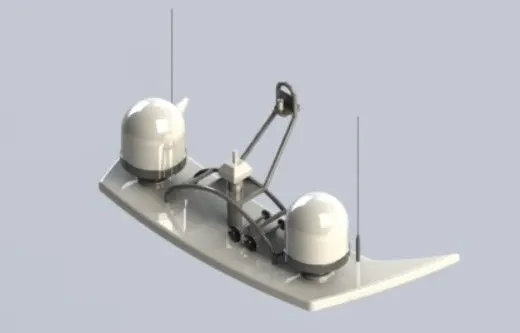
Isometric View
2.
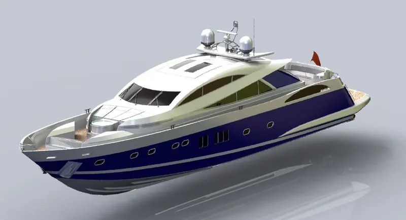
MODELLING AND ASSEMBLING OF SUNSEEKER PREDATOR YACHT
Objective:
The objective is to make detailed models of various parts of a yacht and assemble them to make a yacht model.
Introduction:
- Yacht.
A yacht is a sailing or power vessel used for pleasure, cruising, or racing. There is no standard definition, though the term generally applies to vessels with a cabin intended for overnight use. To be termed a yacht, The term, yacht, originates from the Dutch word jacht (which means "hunt"), and originally referred to light, fast sailing vessels that the Dutch Republic Navy used to pursue pirates and other transgressors around and into the shallow waters of the Low Countries.
- 2. Solid Works
The SOLIDWORKS CAD software is a mechanical design automation application that lets designers quickly sketch out ideas, experiment with features and dimensions, and produce models and detailed drawings.
Design Methodology:
The method for designing the yacht is as follows
1. Designing of parts and their appearance.
2. Assembly of the designed parts of the Yacht.
3. Applying Decals, Camera setup and scene compositions.
4. Final Rendering.
Parts of Yacht:
- Propeller
- Radar
- Hull
- Front seat.
- Middle seat.
- Rear seat.
- Garage door.
- Superstructure.
- Radar master.
Procedure
- Propeller
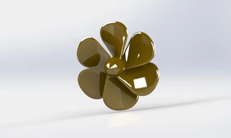
A propeller (colloquially often called a screw on a ship) is a device with a rotating hub and radiating blades that are set at a pitch to form a helical spiral which, when rotated, exerts linear thrust upon a working fluid such as water. The blades are specially shaped so that their rotational motion through the fluid causes a pressure difference between the two surfaces of the blade by Bernoulli's principle which exerts force on the fluid. Most marine propellers are screw propellers with helical blades rotating on a propeller shaft.
Tools Used:
- Sketch
- Line
- Circle
- Loft
- Rectangle
- Revolve
- Circular Pattern
- Fillet
- Extrude Cut
MODELLING PROCEDURE:
- The centre portion of the propeller is sketched and revolved.
- A reference plane is created for the blades of the propeller.
- Create a loft between two rectangles for making the shape of the blade.
- Add fillet on the outer surface of the blade created.
- Make the centre of the propeller hollow with the help of cut extrude.
- Add a fillet to make the edge of the blade smooth.
- Now use a circular pattern for making five more blades.
- Radar
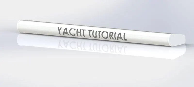
Radars are X-band or S-band radars on ships, used to detect other ships and land obstacles, to provide bearing and distance for collision avoidance and navigation at sea. They are electronic navigation instruments that use a rotating antenna to sweep a narrow beam of microwaves around the water surface surrounding the ship to the horizon, detecting targets by microwaves reflected from them, generating a picture of the ship's surroundings on a display screen.
Radar is a vital navigation component for safety at sea and near the shore. Captains need to be able to manoeuvre their ships within feet in the worst of conditions and to be able to navigate "blind" when there is no visibility at night or due to bad weather. In addition to vessel-based marine radars, in port or in harbour, shore-based vessel traffic service radar systems are used by harbourmasters and the coast guard to monitor and regulate ship movements in busy waters.
Tools Used:
- Sketch
- Extrude
- Fillet
- Line
- Polygon
- Circle
- Text
- Mirror
MODELLING PROCEDURE:
- Draw the required sketch on Midplane and extrude it using Boss Extrude.
- Add fillets on the edges of the extruded surface.
- Make a sketch on either of the edges for end plates and add fillets
- Make four holes on the side plate
- Draw a circle to make a nut on the side plate.
- Make a fillet on the surface of the screw and use a sketch pattern to make four screws.
- Cut a semi-circular slot under the radar at the middle position.
- Mirror the radar through mid-plane
- Add the name of the radar.
- Hull
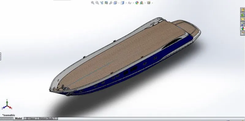
A hull is the watertight body of a ship, boat, or flying boat. The hull may open at the top (such as a dinghy), or it may be fully or partially covered with a deck. Atop the deck may be a deckhouse and other superstructures, such as a funnel, derrick, or mast. The line where the hull meets the water surface is called the waterline.
Tools Used:
- Sketch
- Line
- Circle
- Projected curve
- Linear Pattern Mirror
- Surface Loft
- Extrude cut
- Fillet
- Chamfer
- Sweep Surface
- Knit Surface
- Trim
- Offset
- 3D Sketch
- Plane
- Shell
- Helix
MODELLING PROCEDURE
- Open the blueprint of the yacht in the required plane.
- Draw sketches for creating projected curves for the side of the hull.
- Join the projected curves and loft a surface.
- Remove the extra surface created by using surface trim.
- Use surface loft for creating the rear of the hull and draw a sketch for a flat surface at the rear for mounting propulsion systems and trimming the unwanted area.
- Now use the surface fill option to fill the hull and use the surface knit command to knit all the surfaces.
- Now use the shell command to give desired thickness to the hull.
- Draw a sketch on the mid-plane and extrude it to the inner surface of the hull
- Cut the extra part in the rear upper of the hull
- Now create a sketch on the mid-plane for creating a lower deck
- Add details like windows to the hull. Add fillets to make the corners smooth.
- Make sketches on midplane and top plane for making stairs.
- Create a reference plane make a sketch and give some detailing to the bottom of the hull.
- Add fillets and chamfer to give extra detail to the bottom of the hull.
- Add details on the deck surface for vents and anchor system.
- Make railing by using sketch tool projected curve tool sweep tool
- Draw a sketch for mountings of the propeller using revolve tool sketch tool fillet tool etc.
- Use pattern direction command to create propeller mounting for the second propeller.
- Use a 3d sketch for joining the two mounting to each other.
- Create a new plane for making an anchor on the hull
- Use sketch tool boss extrude, fillet and chamfer tool for making anchor.
- Use cut extrude for making a space in the rear of the hull
- Add decals on the surface of the deck stairs and the second deck
- Now use the mirror tool for making full hull taking mid-plane as reference.
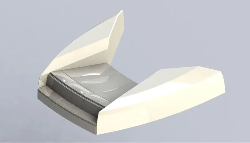
- Front seat
The front seat is placed in front of the superstructure on the hull. It is designed up on the deck surface of the hull. A seat material should have followed quality for better durability, UV resistance, Sturdy hard interior or exterior frame, and corrosion resistance.
Tools Used:
- Plane
- Sweep Structure
- Loft Surface
- Trim
- Extrude Cut
- Resolve
- Surface Knit
- Surface Fill
- Dome
- Mirror
- Fillet
MODELLING PROCEDURE
- Import the blueprint setup of the yacht.
- Draw a sketch on the deck surface.
- Draw a sketch and sweep it to make the side of the front seat.
- Draw another sketch for making the inner surface of the side structure of the front seat.
- Use surface trim to make the final shape generated from the swept surface.
- Fill the surface with the help of the fill surface option.
- Use surface trim to cut a slot on the outer surface of the structure created on two surfaces.
- Make another surface using the surface loft to make a slanting surface.
- Knit all the surfaces and a chamfer at the inner surface.
- Draw a sketch on the inner surface and use revolve option for making the seat structure.
- Use cut extrude for removing an extra portion of the seat
- Draw a sketch on the earlier surface for a cushion of the seat and revolve it to make the required surface.
- Use cut extrude to remove the extra section.
- Add cut extrude for giving detailing to the seat.
- Now mirror the seat section-wise and add fillets for improving details.
- Middle seat
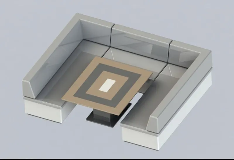
The middle seat is placed just behind the superstructure on the hull. It is designed up on the deck surface of the hull. A seat material should have followed quality for better durability, UV resistance, Sturdy hard interior or exterior frame, and corrosion resistant.
Tools Used
- Extrude Bose
- Chamfer
- Fillet
- Mirror
- Line
- Rectangle
- Cut extrude
- Reference plane
MODELLING PROCEDURE
- Open the blueprint setup and draw the sketch on the surface of the deck.
- Extrude the sketch for making the base of the seat
- Draw another sketch on the extruded surface and extrude the sketch.
- Create another reference plane at the top of the extruded surface.
- Draw a sketch on the new plane and extrude it.
- Create another plane at the top and create a sketch and extrude it.
- Add chamfer to the backrest of the seat.
- Add fillets to make smooth corners.
- Use the mirror option on a section of the seat to make it complete along the mid-plane.
- For making a table use sketch and extrude tools.
- Use cut extrude and fillets tools to give details to the table
- Rear seat
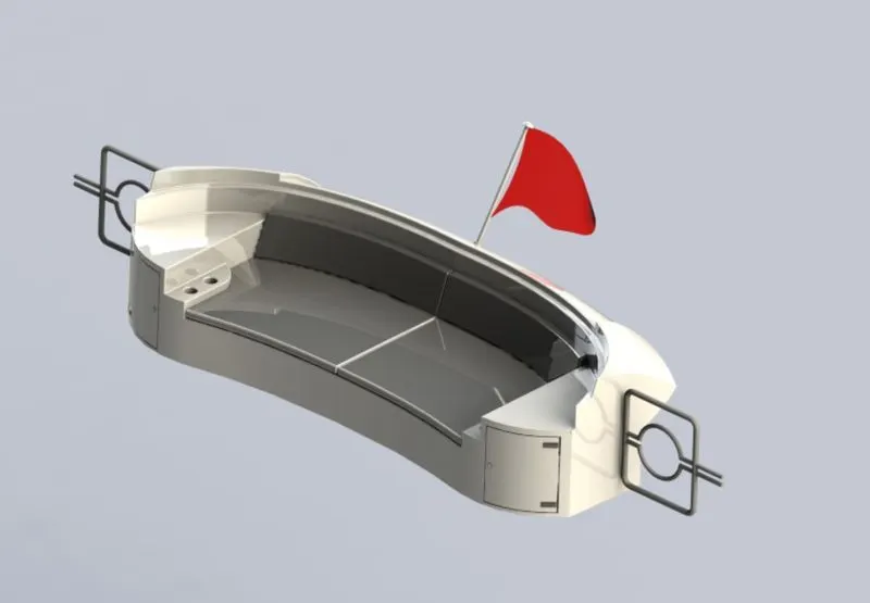
The rear seat is placed at the rear end of the hull behind the middle seat on the hull. It is designed up on the deck surface of the hull. A seat material should have followed quality for better durability, UV resistance, Sturdy hard interior or exterior frame, corrosion resistant
Tools used :
- Surface Extrude
- Surface Offset
- Surface Trim
- Sweep
- Ruled Surface
- Surface Extend
- Surface Knit
- Extrude Bose
- Chamfer
- Extrude Cut
- Mirror
- Plane
- Fillet
MODELLING PROCEDURE
- Open the blueprint setup and insert the deck surface for reference.
- Draw a sketch on the midplane
- Create a new plane and draw a sketch for sweeping the earlier sketch.
- Use surface offset to make the second half of the rear seat
- Use the ruled surface tool to extend the second half of the seat.
- Use a knit surface to knit the ruled surface and rear of the seat.
- Draw a sketch on the bottom plane and use it to remove the extra part in the rear seat.
- Use surface sweep and surface extension for joining the two sections of the rear seat.
- Use surface trim to remove the extra section in the extended section.
- Draw a sketch on the bottom plane with the help of convert entities and extrude it to cover the end of the seat.
- Use surface trim to remove the extra section in the extruded end surface and knit all the surfaces.
- Use convert entities to create the front end of the backrest and extrude it.
- Use a surface loft to cover the corner of the seat and knit all the surfaces.
- Use the surface loft option to cover the bottom of the seat.
- Use the surface extend option to eliminate any gap remaining in the lofted surface then trim the extra surface
- Knit all the surfaces.
- Draw a sketch on the bottom plane and extrude it to make a seat.
- Draw a sketch on top of the extruded surface to make an armrest area.
- Use cut extrude to make a glass holder and cabinet door in the seat.
- Create a new plane and draw a sketch for making hinges and door handles.
- Use surface offset to make a bottom section of the cushion of the seat and extrude it.
- Draw a sketch on the same plane which was used to create hinges for the rear light.
- Draw a sketch by using convert entities on the top surface of the seat and extrude it to make the backrest of the seat.
- Add chamfer and fillets to add details to the seat
- Make two reference planes to make a gate at the side of the seat
- Draw the sketch to make the path to make a sweep.
- Use a mirror to make the top part of the gate
- Use mirror-taking midplane as a reference and make other sections of the seat.
- Garage door
A garage door is a large door in a garage that opens either manually or by an electric motor (a garage door opener). Garage doors are frequently large enough to accommodate automobiles and other vehicles. The operating mechanism is spring-loaded or counterbalanced to offset the weight of the door and reduce the human or motor effort required to operate the door. Less commonly, some garage doors slide or swing horizontally. Doors are made of wood, metal, or fiberglass, and may be insulated to prevent heat loss.
Tools Used:
- Extrude cut
- Mirror
- Text
- Fillet
- Shell
- Plane
MODELLING PROCEDURE
- Import the Solid body split which was made while designing the hull for modelling the garage door.
- Use extrude cut to remove the extra section to get the final shape of the garage door.
- Use the shell command to get the needed thickness of the door.
- Add fillets to the inner surface of the door.
- Use the cut extrude command for creating a hole for the installation of the door to the main body of the yacht.
- Make fillets at the outer corner of the door for making a smooth surface.
- Use mirror command along the midplane to make the rest half of the door.
- Make a plane parallel to the front plane at a certain distance for mentioning the name on the door with the help of the cut extrude command.
- Superstructure
A superstructure is an upward extension of an existing structure above a baseline called ground level and it usually serves the purpose of the structure's intended use. A superstructure is a decked structure on the freeboard deck, extending from side to side of the ship.
Tools Used:
- Line
- Spline
- Circle
- Extrude cut
- Projected curve
- Offset
- Surface fill
- Surface extrudes
- Surface sweep
- Dome
- Surface trim
- Extend surface
- Surface knit
- Plane
- Ruled surface
- Split Entities
- Split lines
- Delete faces
- Fillet
- Chamfer
- Mirror
MODELLING PROCEDURE
- Open blueprint setup and use the deck surface for reference.
- Draw a sketch on the deck surface and use the surface extrude command.
- Add a ref. plane at the end of the curved surface of the extruded surface.
- Draw a sketch on the new plane and sweep along the extruded surface and knit them together.
- Add a fillet to make the corner smooth then use a ruled surface at a certain angle for the inclined surface.
- Now trim the extra surface from the ruled surface area.
- Now draw two projected curves for the upper side surface of the structure and use the Loft surface.
- Make a reference plane on the flat surface rear end of the bottom panel.
- Draw a sketch on the plane and a 3D sketch and use a sweep surface then remove the extra surface with the help of surface trim.
- Draw a sketch on mid-plane for the upper deck surface then trim the extra surface.
- Use surface fill, and surface loft for making a curved section for making the rear panel.
- Use a Knit surface to knit the required surfaces.
- Use the surface loft option to make the top panels of the superstructure.
- Use convert entities for making a 3D sketch and the use ruled surface to make side glass of the superstructure then trim the unwanted surface.
- Use a surface loft to fill the gap between the glass surface and a panel of the structure.
- Use extend surface to extend the top surface at the rear end and trim the unwanted surface.
- Use loft surface, and ruled surface to create surfaces to fill the gaps.
- Knit all the surfaces.
- Make a sketch on the deck surface to enclose the rear of the superstructure.
- Use surface extend surface trim to make the front of the superstructure
- Make stairs at the front of the superstructure.
- Make a sketch on the surface deck for the jacuzzi by using revolve command and trim the extra surface created.
- Add details like grab rail at the required area, cushions on the front of the deck, windshield and side glasses etc.
- Mirror the whole structure along the midplane.
- Create a surface for mounting the Radar master.
- Make wipers by using the 3D sketch Bose extrude sweep command.
- Make a dome for creating a water surface in the jacuzzi.
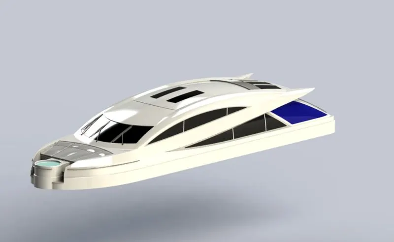
- Radar mast
A mast is a vertical ship structure mounted on top of the bridge and forward of the forecastle towards the ship’s derrick and holds necessary equipment such ass radar, navigation lights and ship's horn in case of the foremast. They are made of high tensile steel with added rigidity based on the size of the derrick it holds. Other than that, a ship's main mast is also used to hoist the ship's flag.
Out of different parts of the ship, the main job of the mast is to hold necessary equipment such as radar receiver, navigation lights, ship horn, and derrick in some cases. Out of different parts of the ship, the main job of the mast is to hold necessary equipment such as radar receiver, navigation lights, ships horn, flags and derricks in some case
Tools Used:
- Line
- Spline
- Extrude bose
- Revolve
- Circle
- Mirror
- Line
- Fillet
- Chamfer
- Shell
- Projected curve
MODELLING PROCEDURE
- Open the blueprint setup and use the surface we have created from Superstructure for locating the radar master.
- Draw a sketch on Midplane.
- Add A reference plane along with the sketch drawn earlier.
- Draw a sketch on the new plane and extrude it for the base of the radar.
- Use fillets to make the corner smooth.
- Take another reference plane perpendicular to the base surface.
- Draw a sketch on plane two for the body of the radar.
- Add fillets for smooth corners.
- Draw a sketch on the base of the radar for the Antenna and extrude it at the different radii and different heights.
- Add Fillets for the Antenna for more details.
- Make two reference planes one parallel to the backplane and another coincident to the flat surface of the radar base.
- For the lamp stand use the fourth plane and sweep the sketch drawn on the plane.
- For foot steps draw three circles on plane 3 and extrude it.
- Use sketch, sweep and extrude for creating a stand from the base of the radar.
- Use chamfer and fillet to give it extra details
- Draw a sketch on plane 3 for making the top part of the stand and extrude it.
- Use a mirror to mirror the top part of the stand.
- Draw a sketch on the bottom side of the base of the radar and extrude it to join the radar to the superstructure surface.
- Make another ref. a plane parallel to the mid-plane.
- Use revolve command to make the horn on plane 3.
- Apply shell command, Dome and fillet to add details to the horn.
- Use mirror command on horn and radar master separately.
Features
- Circle:
Circle is an important sketching tool which enables to create the circular drawing on the plane.
- Rectangle:
A rectangle is a sketching tool for drawing squares, rectangles, parallelograms etc.
- Spline:
Spline is used to create a three-dimensional curve defined by a set of control points.
- Sketch fillet:
It is used to create a tangent arc between two sketches.
- Offset Entities:
It is used to copy a specific entity to a certain distance from the original entity.
- Convert Entities:
This command allows you to copy a edge into the active sketch. These sketches are already defined by previously mentioned constraints.
- Extrude Boss/Base:
This command allows us to add thickness to a 2D sketch to make it a 3D part.
- Extrude Cut:
This command is used to remove extra projection from already created parts.
- Dome:
This command is used to insert a dome surface on an existing part.
- Projected Curve:
This command is used to project a 3D curve from already created sketches.
- Lofted Surface:
This command is used to create a lofted surface between two sketches.
- Boundary Surface:
This command is used to create a surface tangent to both surfaces used as a guide, using this command gives a better smooth surface.
- Extruded Surface:
This command is used to Extrude a sketch or sketch contour at a certain distance to create the surface.
- Revolved Surface:
This command is used to create a revolved surface of a generated sketch along a given axis.
- Swept Surface:
This command is used to create a closed profile along an open or closed path to create a surface.
- Filled Surface:
This feature is used to fill the patches of a surface within a boundary defined by sketches or curves to improve the surface finish.
- Ruled surface:
This command Inserts ruled surfaces in a specified direction from the edges. Tangent to the surface, Normal to the surface, tapered to vector, perpendicular to vector or sweep can be selected.
- Trim Surface:
This command trims the surfaces where a surface intersects with another surface, a plane, or a sketch
- Knit Surface:
It combines two or more adjacent, non-intersecting surfaces into a single surface body
- Move or Copy Surface:
Moves or copies surfaces about a plane or a sketch
- Offset surface:
This command is used to create an offset surface with a certain gap by using one or more continuous faces.
- Extend Surface:
This command is used to extend one or more edges or faces on a surface based on end conditions and extension type.
- Mirror Surface:
The mirror command is used to mirror the selected feature about a plane or planner face.
- Reference plane:
The reference plane command is used for creating a new plane with reference to any surface or plane.
- Split line:
This command is used to divide selected sketch, solid, surface, or plane and we can split curves on multiple bodies with the command.
- Split point
We can split a sketch entity to create two sketch entities. Conversely, we can delete a split point to combine two sketch entities into a single sketch entity.
- Fillet:
A fillet is an internal rounding of a corner or edge in a sketch or an edge on a surface.
- Lofted surface:
- Chamfer:
- Combine:
- Surface fill:
- Assembly Commands:
Smart Mate - A Smart mate is an assembly mating relation that is created automatically.
Mate - A mate is a geometric relationship, such as coincident, perpendicular, tangent, and so on, between parts in an assembly.
Mate group - A mate group is a collection of mates that are solved together. The order in which the mates appear within the mating group does not matter.
Sub-Assembly - A sub-assembly is an assembly document that is part of a larger assembly. For example, the steering mechanism of a car is a subassembly of the car.
Insert Components - We can insert multiple instances of the group of components without closing the Property Manager.
- Assembly Procedure:
Import all the parts manually by using the Insert Components option.
Then fix the Hull part by applying the coincident mate to the Top, Right and Front planes of the Assembly and Hull respectively.
Then for each part apply the necessary mates required by the Blueprint using Coincident mates, Angle Mates, Distance mates etc.
The advanced mate was also used wherever required.
- Mates
Mates establish geometric relationships between components of the assembly. We define the permissible directions of linear or rotational motion of the components as we add mates. Within their degrees of freedom, we can transfer a component, envisioning the behaviour of the assembly.
- Insert parts.
In this feature, the other components that need to be mated with the prime fixed component can be added
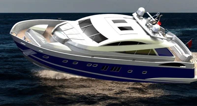
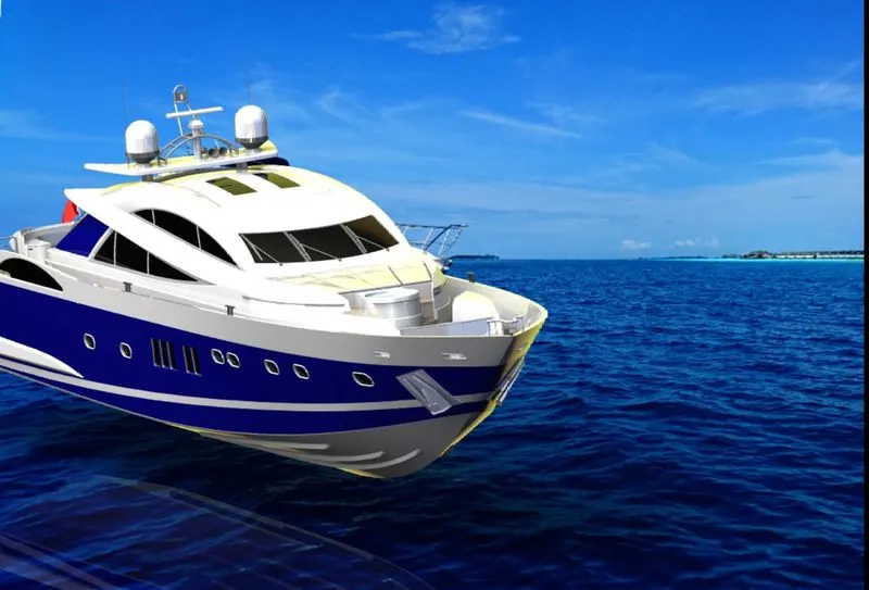
Front View
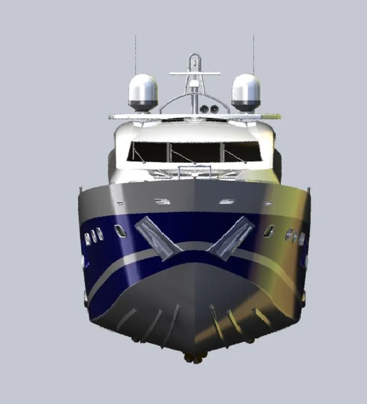
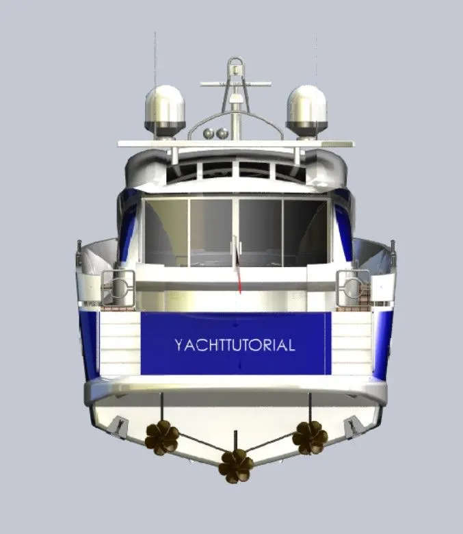
Back View
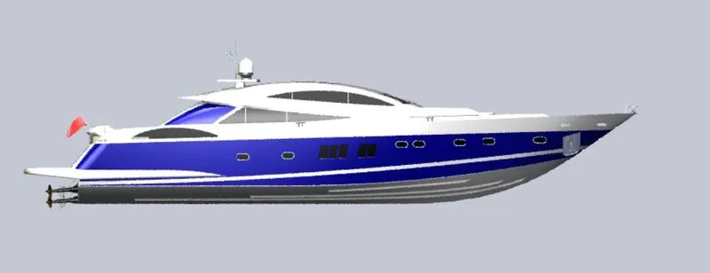
Left View
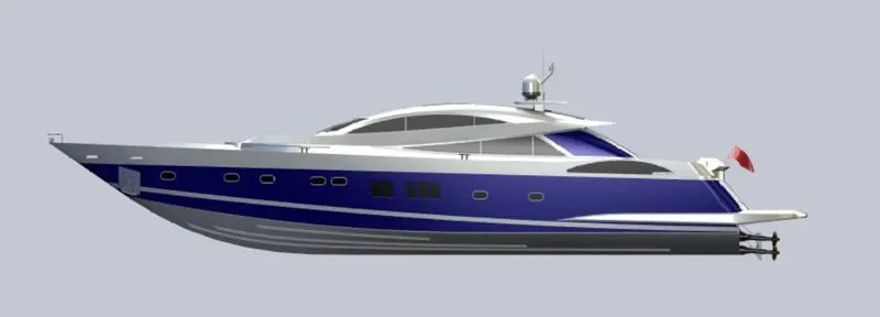
Right View
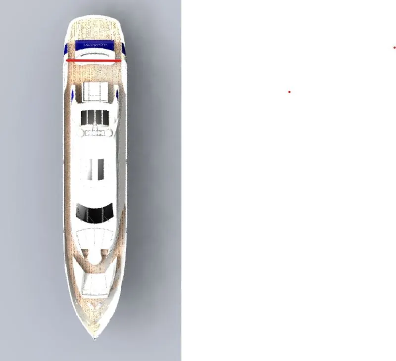
Top View
Bottom View
Isometric View