Photo Realistic Rendering
MODELLING AND RENDERING OF AMERICAN CHOPPER
Objective
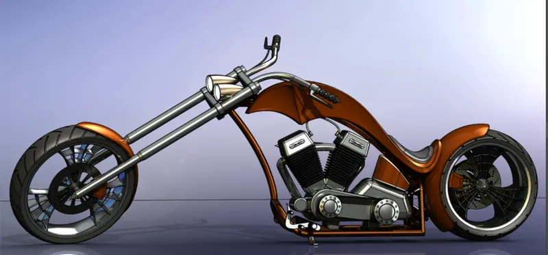
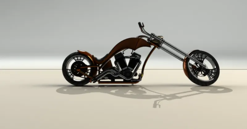
To make an American chopper model and photo realistic render in Solid works.
Modelling
The chopper has following parts which are designed separately and assembled together and the commands or features used are mentioned as per parts below.
INTRODUCTION
American chopper is a kind of motorcycle which has long wheelbase low upright seating position and higher rake angle for better handling and comfort, has low ground clearance. These bikes have foot steps positioned in such a manner that the rider has to extend his/her legs forward with high and wide handle. This kind of setup is created for comfort of the rider for long ride while compromising cornering ability.
We have created American chopper in solid works in following two sections.
- Creating Part
- Assembling parts
1.CREATING PARTS: Modelling in solid works has two approaches first feature and second parametric which is done simultaneously.
Parametric approach (Length, width, diameter, Tangency, collinearity, position.) determines the geometry and shape of the part/assembly.
Feature approach is used to convert 2D sketches to 3D model using different features such as (extrude, revolve, fillet, chamfer, loft, sweep. Etc.
2.ASSEMBLING PARTS: Assembly of parts can be done in assembly environment with the help of mates which determines the final relation between various parts some of the common mates used mates are, Concentric, parallel, tangency, width, angle, limit angle etc.
DESIGN METHODOLOGY
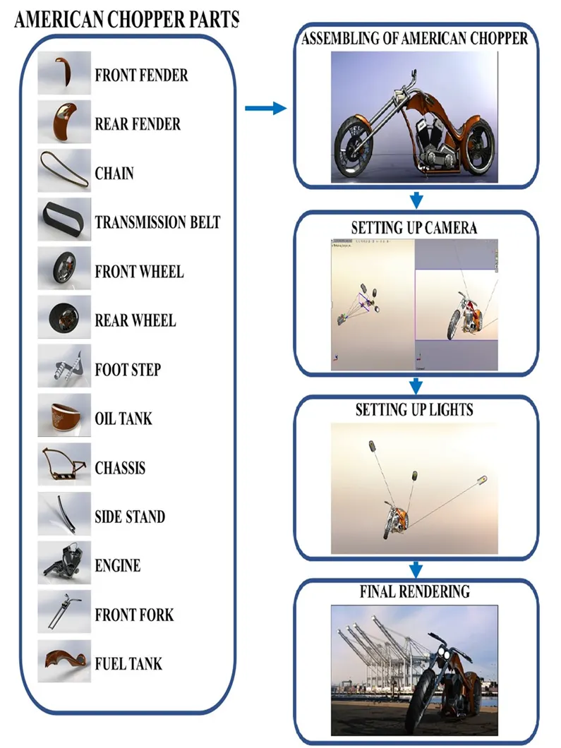
PART DISCRIPTION
- CHASSIS
Chassis is part of a bike on which every part is mounted on. The chassis must be strongest part of the bike to withstand all the forces generated (tensile compressive shear stresses) while other parts are working. It also consists of mounts for mounting of various parts such as foot step, Side stand, engine, front fork, rear wheel etc.
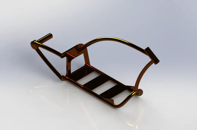
COMMANDS USED: Sketch picture, line, circle, Cut Extrude, projected curve, Fillet, chamfer, spline, Boss Extrude, Revolve, split, Sweep, Mirror, Plane creation, Dome, Combine.
PROCEDURE
- Start by renaming top and front plane as bottom plane and mid plane chassis respectively.
- Place the picture of the chopper on mid plane chassis
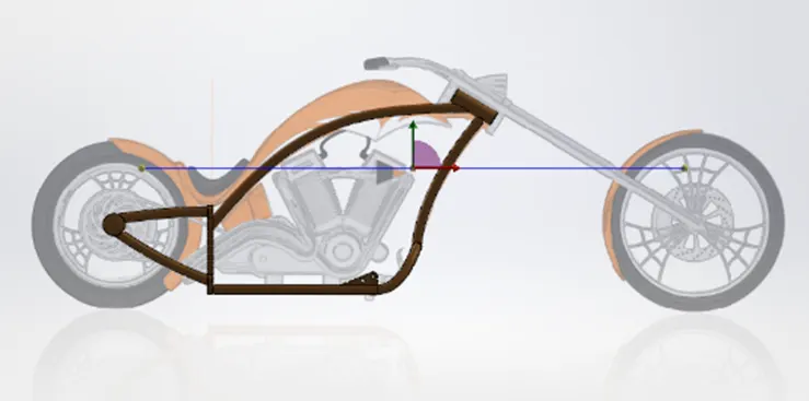
- Take reference of the chopper picture and draw the required splines, lines and sweep command for frame of the chassis.
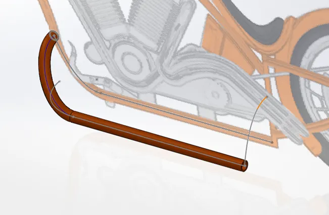
- Use projected curve feature to make complex shaped hollow tubes.
- Make back plate of chassis and use cut extrude feature to remove the portion in the plate.
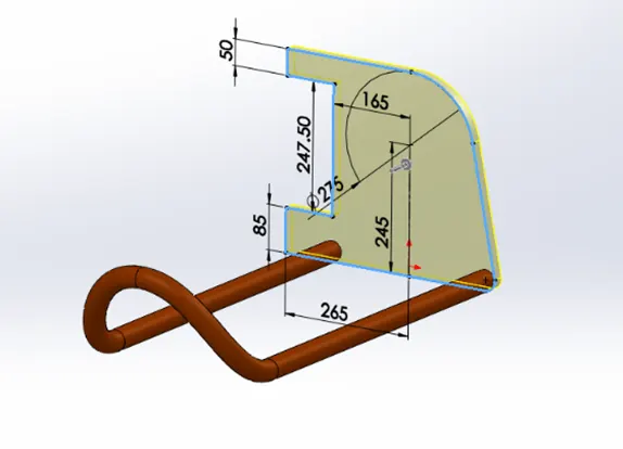
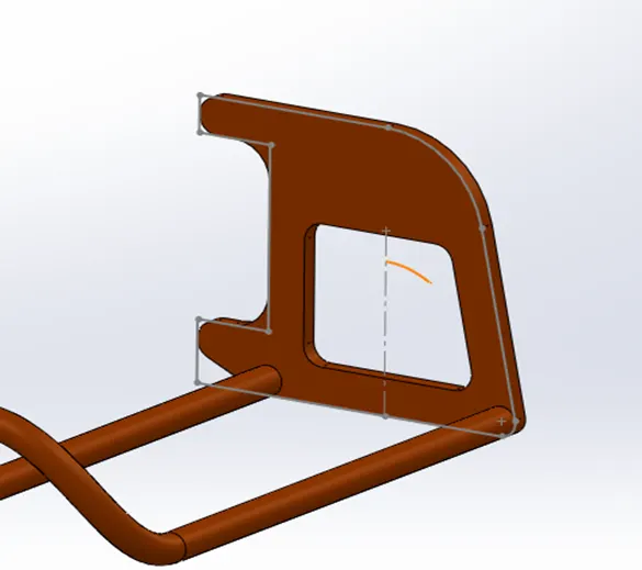
- Sweep the swing arm on the plane of the plate created. Then create a hub axle.
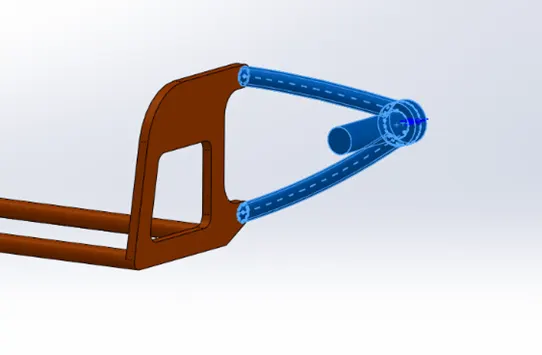
- Sweep the other sections required. And use split and consume bodies command to remove the extra hollow tube.
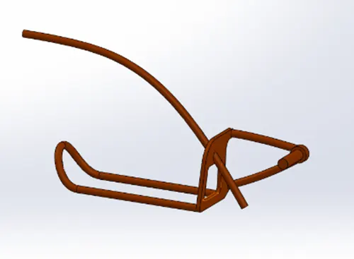
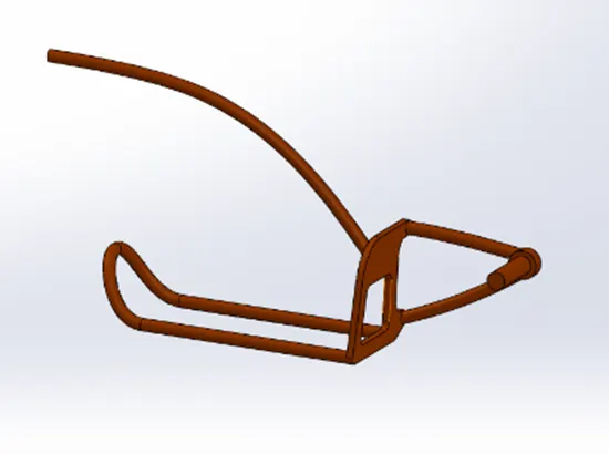
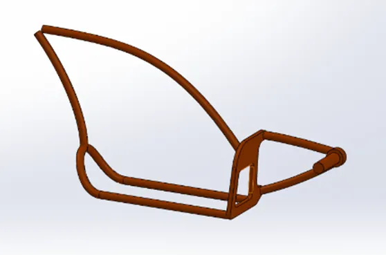
- Create a steering stem by using revolve command and then use split to consume bodies at the intersection
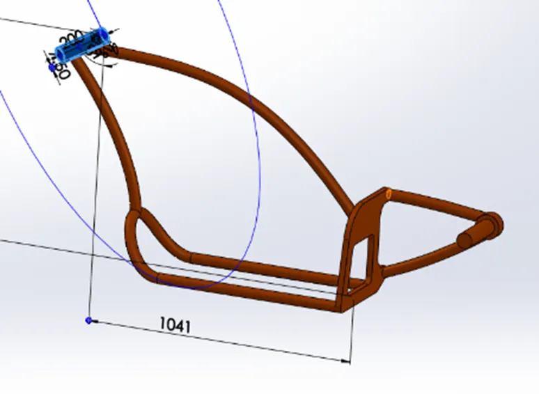
- Create chassis base plate extruding the plate sketch with the help of up to next extrude function
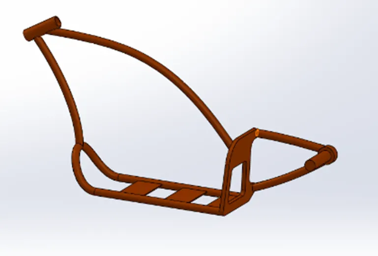
- Create foot peg mounts.
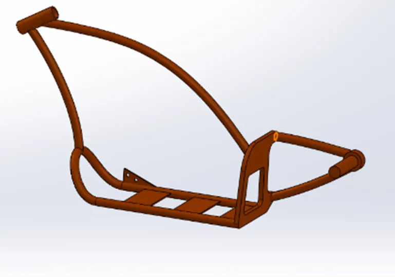
- Create a side stand mount.
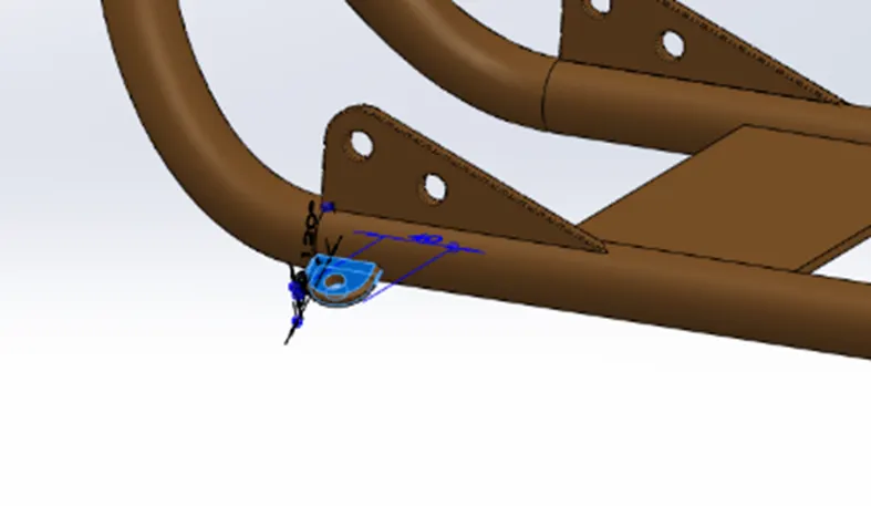
- Apply fillets and chamfer as required.
- Combine all the bodies in to one.
- Apply paint from Appearance column.
- ENGINE
Engine is component of the vehicle which generates the power for motion of vehicle. Generally, bikes have I.C. engines here we have designed twin cylinder engine. It mainly consists of air intake, cylinder block, cylinder head, gear box, transmission belt, spark plug, fuel intake system, exhaust pipe etc.
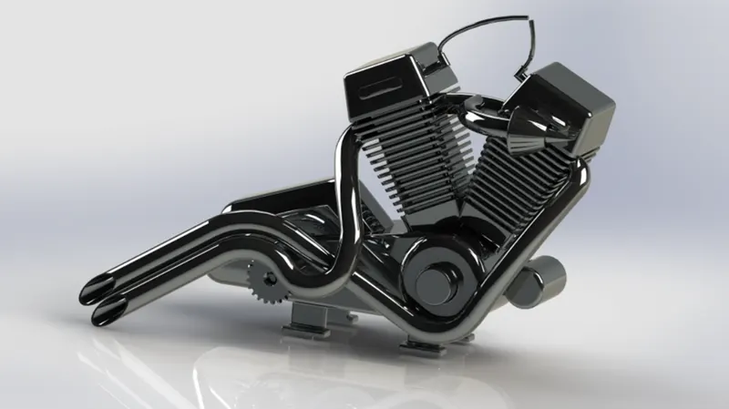
COMMANDS USED: Sketch picture, line, Circle, Spline, Boss Extrude, Fillet, Revolve, Circular pattern, Dome, Cut Extrude, Linear pattern, chamfer, three-point arc, Split, Projected curve, Combine, Mirror, Sweep.
PROCEDURE
- Open picture of chopper for reference on front plane.
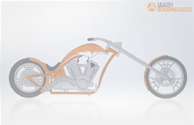
- Create a sketch of base of engine taking picture as a reference.
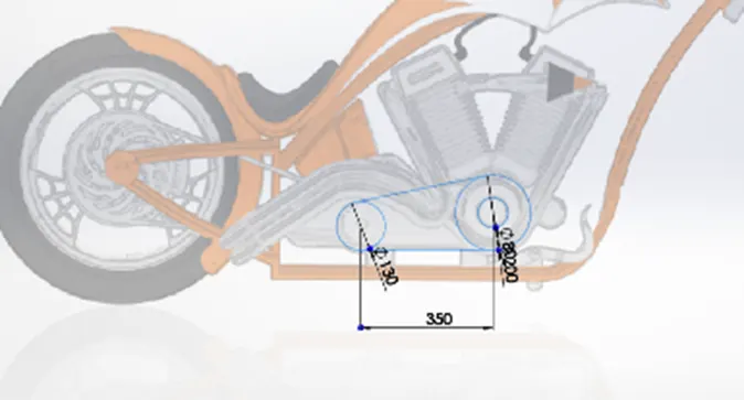
- Sketch the pulleys for installation of transmission belt
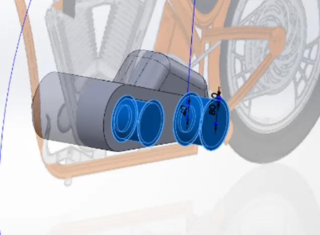
- Make rectangular cross section for better grip of belt on pulley by using circular pattern with reference to pulley.
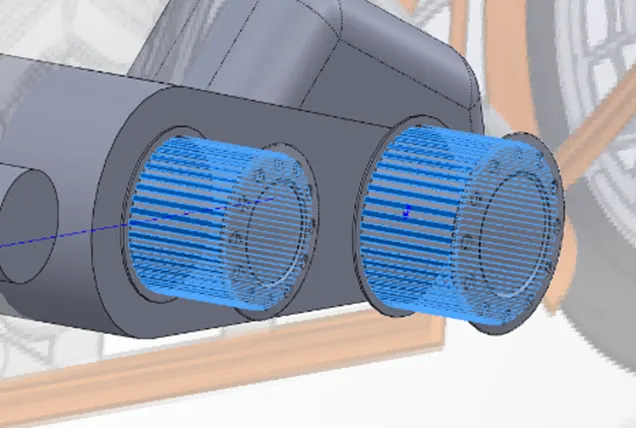
- Create a dome on both the pulleys.
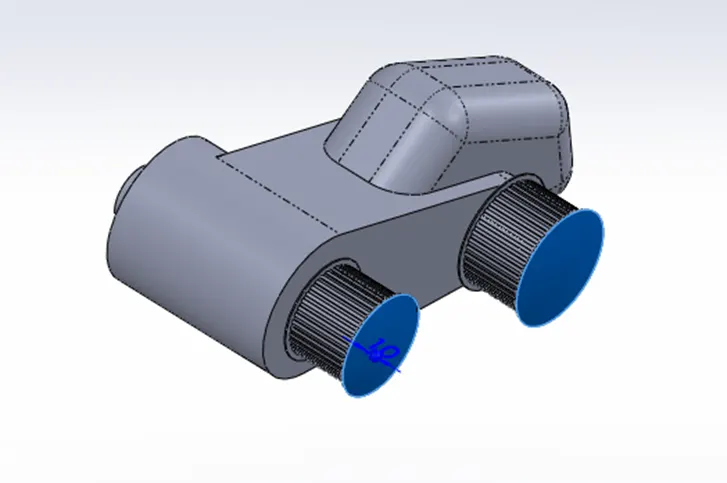
- Create a sketch for starter motor and extrude it as required.
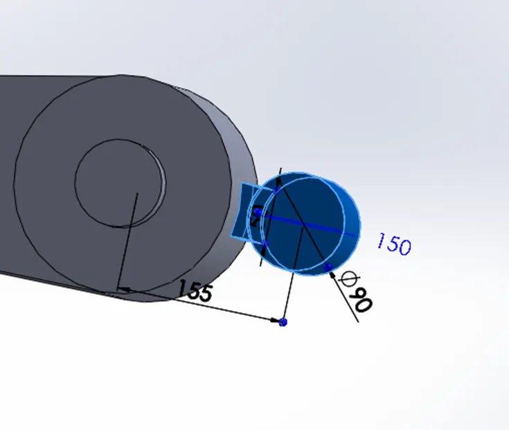
- Create a centre line for engine block and extrude a rectangle accordingly.
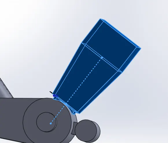
- Create fins on engine block with the help of linear pattern.
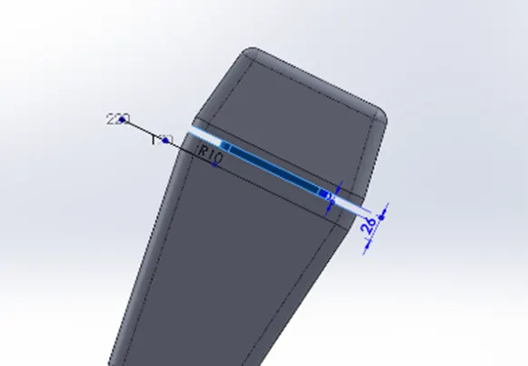
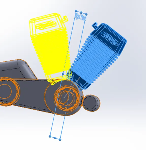
- Mirror the engine block across the right plane to create second engine block.
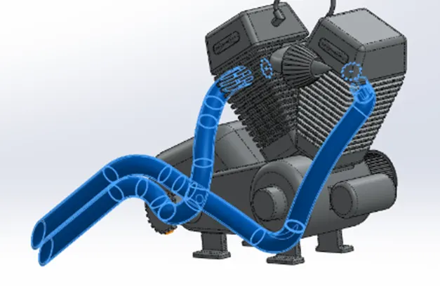
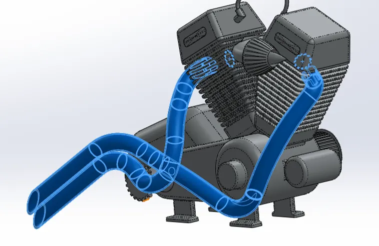
- Use splines and projected curves to create path for sweeping of exhaust pipe.
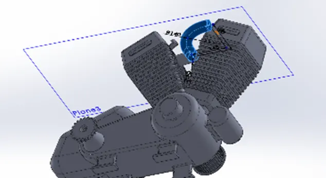
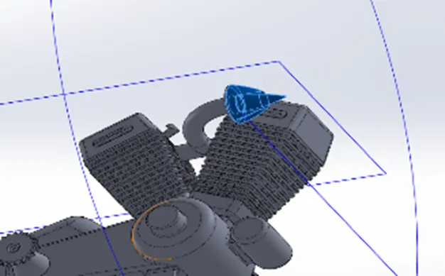
- Use spline revolve and projected curve to make air intake manifold and provide cuts on the air filter by using cut extrude command.
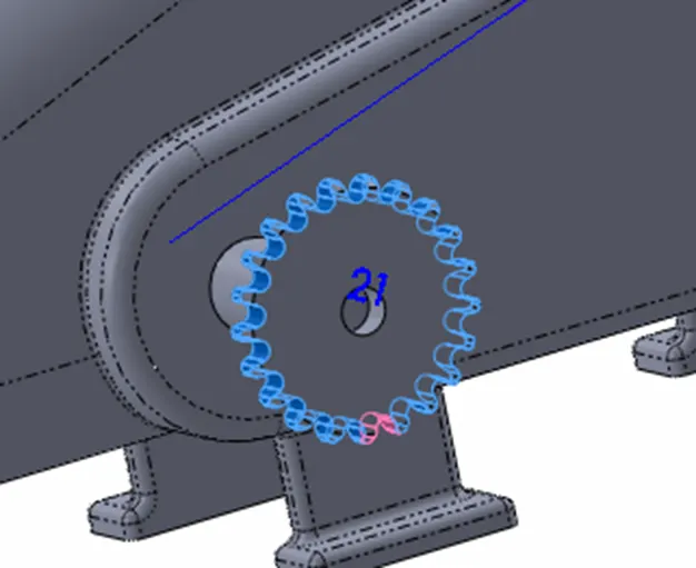
- Make a sprocket by using boss extrude cut extrude and circular pattern for mounting chain and provide a chamfer near sprocket.
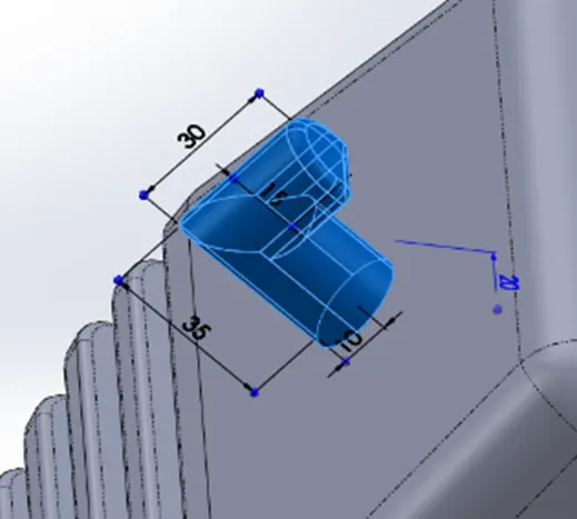
- Make spark plug by using boss extrude spline sweep and fillet functions.
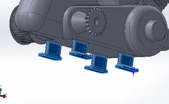
- Make mounts on bottom of the engine.
- Make fillets as required for a smooth surface transition.
- Apply appearance to the engine
- OIL TANK
Oil tank is used for storing oil for lubrication and cooling of engine parts for less wear and tear of engine components.
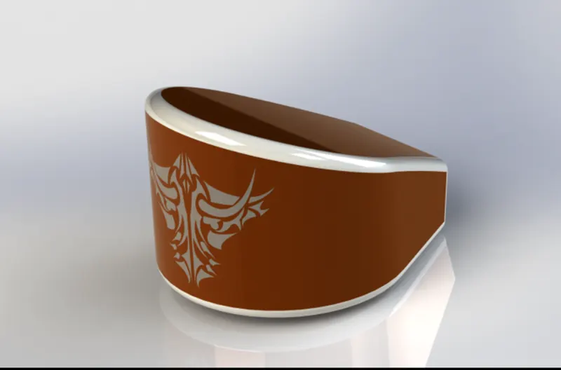
COMMAND USED: Sketch, Line, Point, three-point arc, Spline, combine (common), Fillet, Shell, Boss Extrude.
PROCEDURE
- Start by renaming front plane to mid plane oil tank.
- Sketch on top plane as in below image and extrude it both side by defining distance both sides.
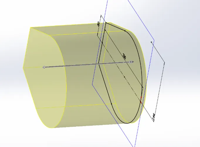
- Make reference point
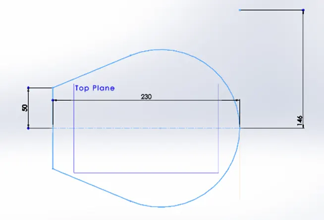
- Create a sketch on mid plane and extrude in both directions.
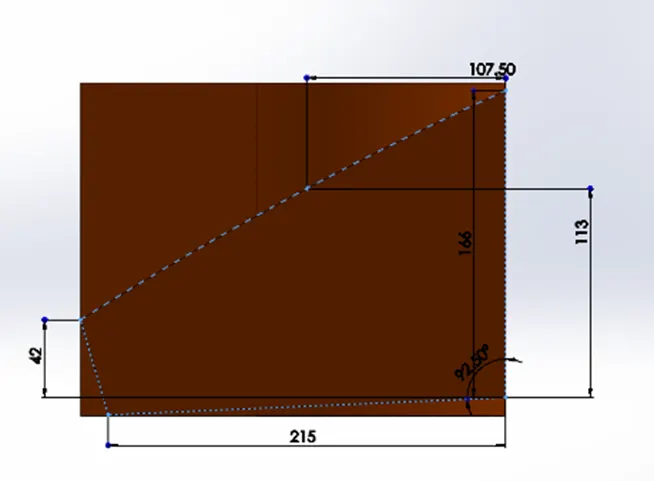
- Use combine feature and keep the common section in both extruded sections.
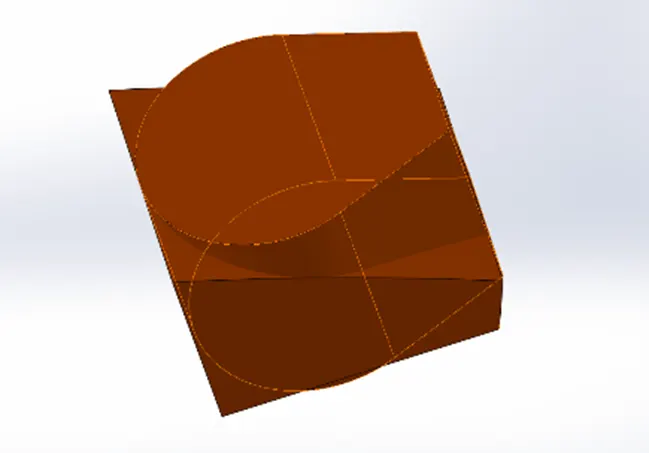
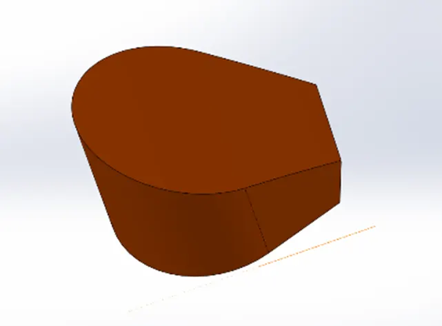
- Apply fillets at corners as in image.
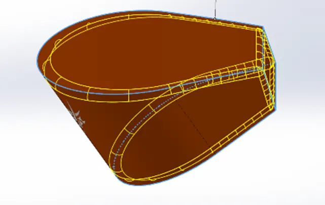
- Create a shell to make it a hollow tank
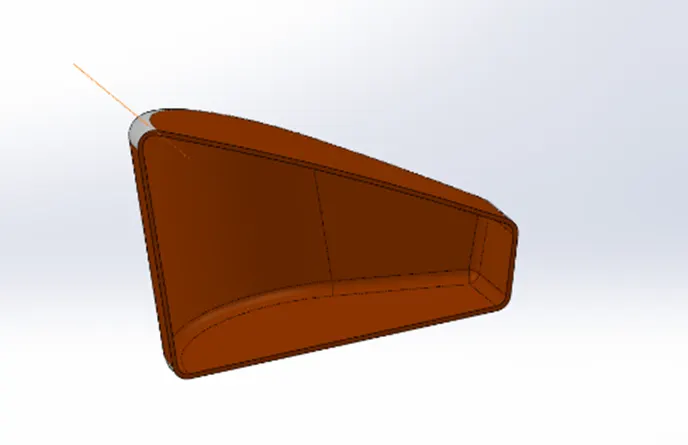
- Apply appearance to the tank.
- CHAIN
The chain consists of many links (plates) and pins which are connected with each other, chain is used to transmit power from engine to wheel through sprocket. Chains are used because of low cost, efficient power transmission.
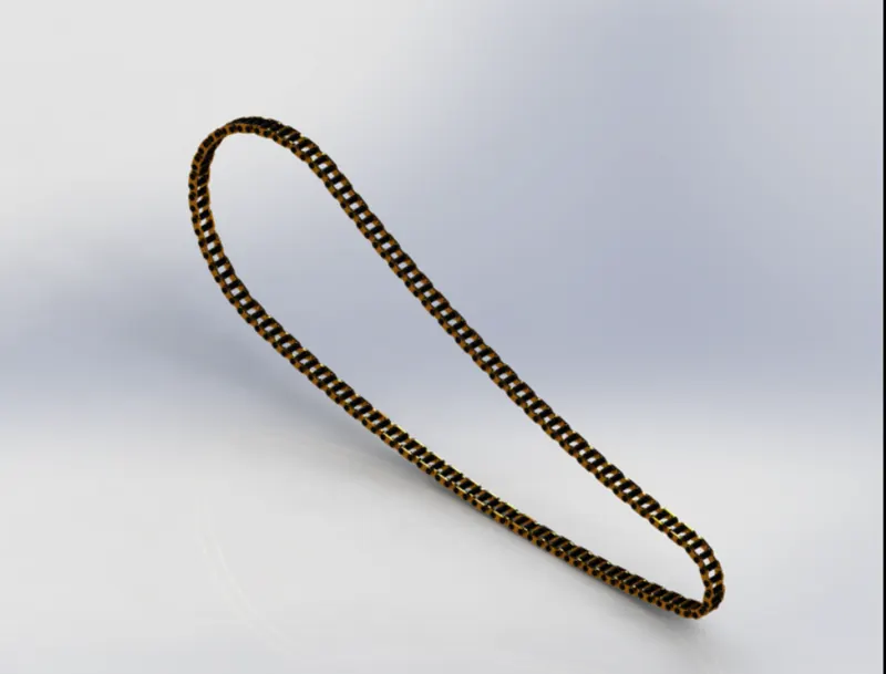
COMMAND USED: Sketch, Circle, Line, Three Point Arc, Trim, Mirror, Blocks, Curve driven pattern, convert entities, Mirror, Boss extrude, Body delete/keep, Fillet.
PROCEDURE
- Rename the front, top, and right plane as midplane, center plane, and front plane respectively.
- Sketch the path of the chain with the help of a circle three-point arc, and construction lines.
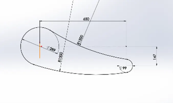
- Create two chain links and make blocks of them to reuse them.
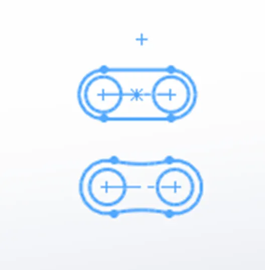
- Select blocks of chain link one and chain link two and place them on the section of the path by fixing it with coincident and concentric commands.
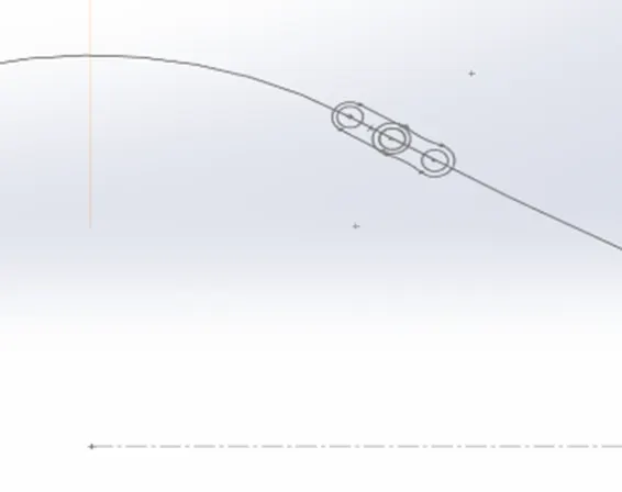
- Extrude link one pin and link two separately one offset extrudes and another extrude from vertex
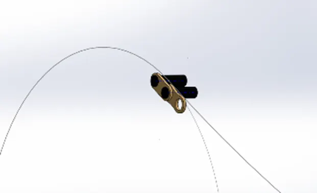
- Apply fillets on the links and the pin.
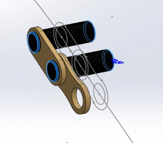
- Use linear pattern curve for repeating the chain links through path.
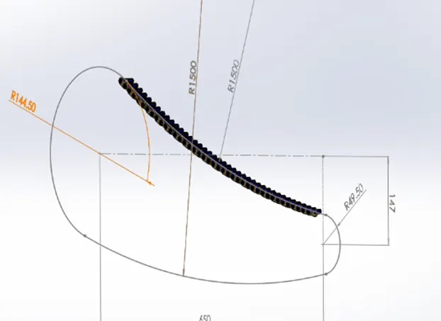
- Repeat the process of placing and patterning the links and pin at each of the remaining three sections of the path with the required number of copies.
- If required change the last link for proper fit of the links by modifying the same link.
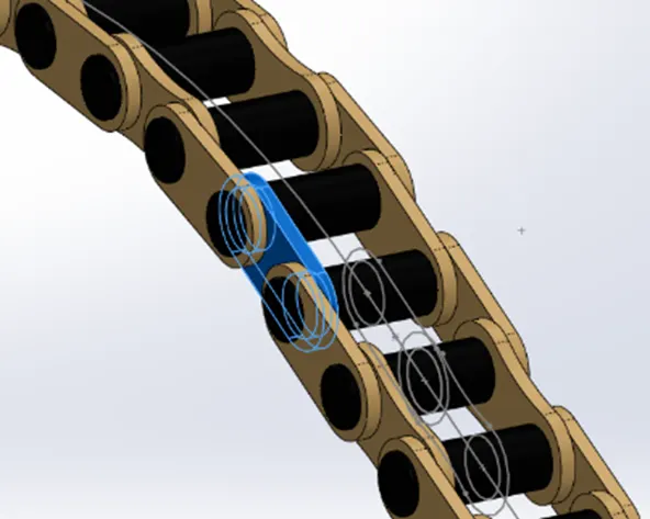
- Mirror the links along the chain path.
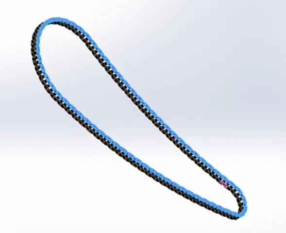
- Apply the appearance to the chain.
- FRONT WHEEL
The wheels of the bikes are very important component of the bike because it is the only connection between the ground and the bike, a good front wheel is required for proper maneuverability of vehicle. It consists of rim, tyre and brakes etc.
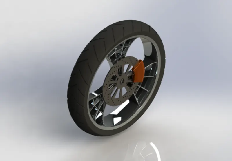
COMMAND USED: Sketch, Line, Revolve, Boss Extrude, Cut Extrude, Boss extrude (off set), Chamfer (distance/distance), Offset entities trim, three-point arc, revolve cut, circular pattern, combine, intersection curve.
PROCEDURE
- Rename the front plane as front plane front wheel
- Create a horizontal mid-point line on the front plane origin, and make an enclosed sketch by making a rectangle.
- Make a horizontal line above the origin and make a vertical relation between mid-point of line and origin.
- Make a three-point arc and make its center aligned with the line and the end point of arc must be in horizontal relation between each other.
- Join the points of arc with the line above through lines and insert fillets for producing smooth surface.
- Give a vertical distance between the arc and the upper line.
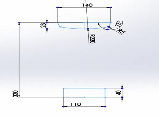
- Revolve both the sketches along the line passing through origin.
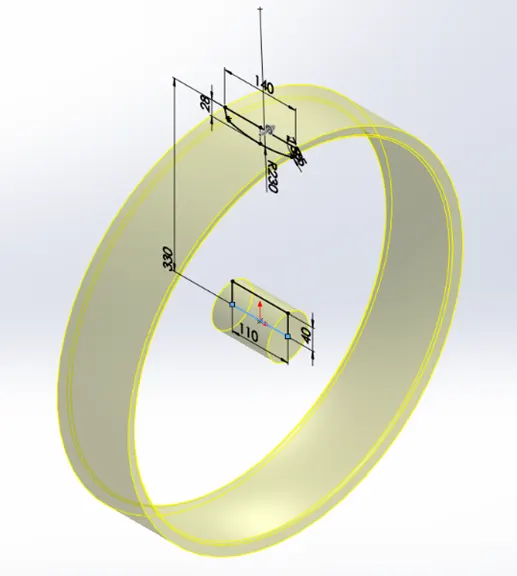
- Now create sketch for spokes and extrude it and define its position with respect to the wheel
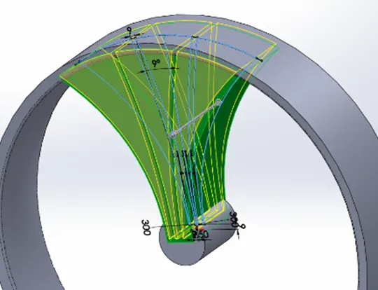
- Make another sketch for creating splines then use extrude cut to make the required spoke design.
- Make a sketch on the front plane to remove material from the spork for removing material use revolve cut option.
- Use a circular pattern to replicate the spoke design created and combine all three-spoke, hub, and rim together.
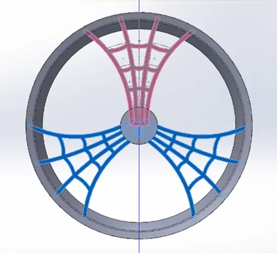
- Apply fillets on spokes as required.
- For the brake rotor sketch a circle and extrude it using the offset option.
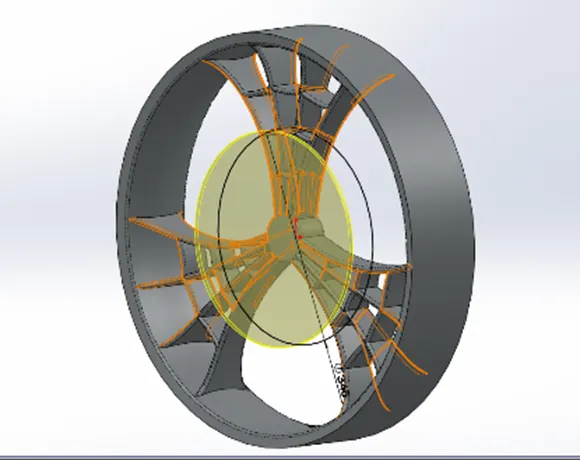
- On the disc created make a hole through extrude cut (up to next) for ventilation of the disc.
- Use the circular pattern to replicate the holes for ventilation as per requirement.
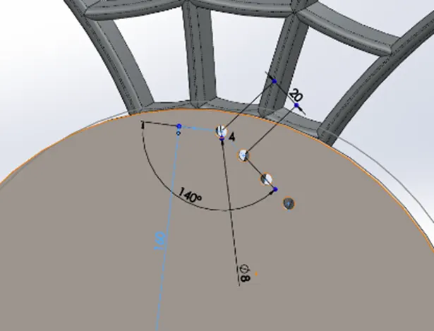
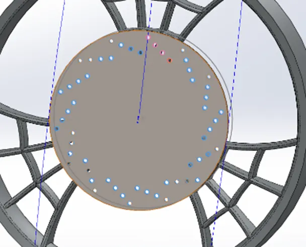
- Make a sketch to cut slots in the disc apply fillets and use the circular pattern to create slots on the disc.
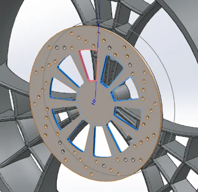
- For creating brake calipers make two circles of req. diameter.
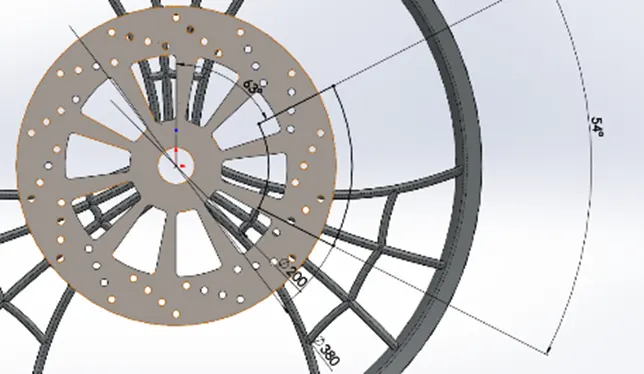
- Make a vertical construction line above the center of the rotor.
- Sketch two lines connecting two circles. Having a certain angle between them.
- Apply an angle dimension between the construction line and the upper line of calipers.
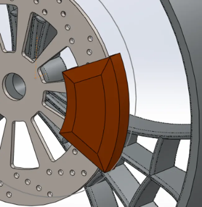
- Now extrude the sketch in both directions by defining the distance of both sides.
- Apply distance-distance chamfer and fillets to the calipers.
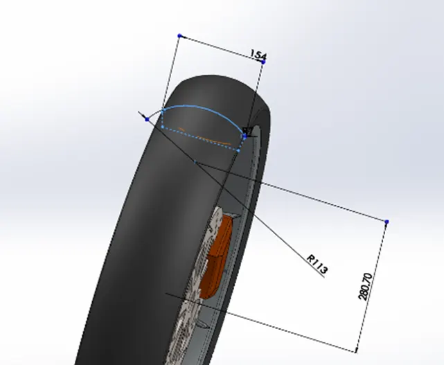
- For making tyre, use convert entities on outer side of rim and make a three-point arc.
- Make the end point of arc horizontal and center of the arc should have a vertical relation with the origin.
- Sketch two lines to join the arc with the converted line to get a closed shape.
- Use fillets at corners.
- Revolve this sketch around the center axis.
- For threads on the wheel sketch on front plane as required.
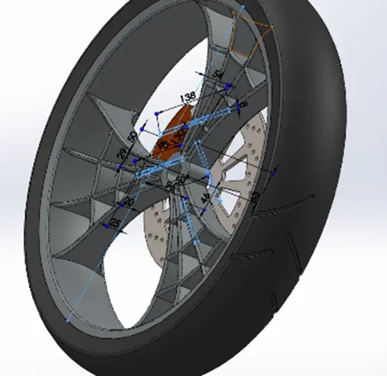
- Convert the rim edge in to sketch and make it construction.
- Use extrude cut offset from the surface of tyre
- Keep the feature scope to the tyre only.
- Apply fillets on the corners of the threads cut.
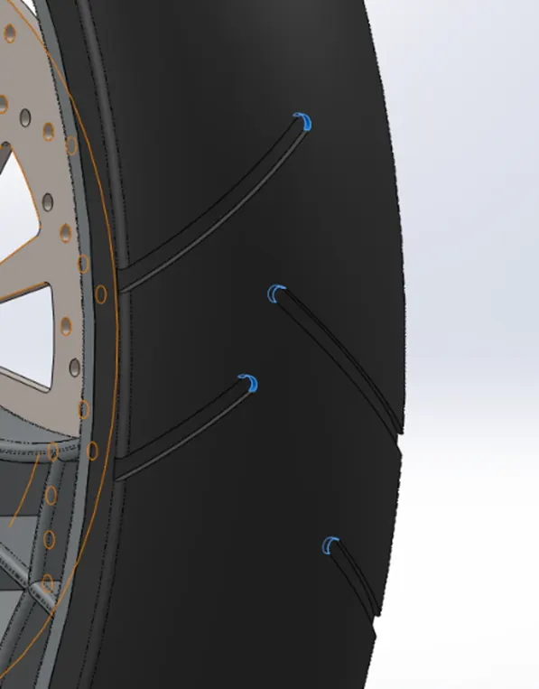
- Use circular pattern to apply threads on the whole surface of tyre.
- Apply appearance.
- FRONT FORK
Front fork of the American chopper is generally longer than other bikes and has a high rake angle for better maneuverability. The main components mounted on front fork are head lights, Handle bar, front wheel, front fender, brakes etc.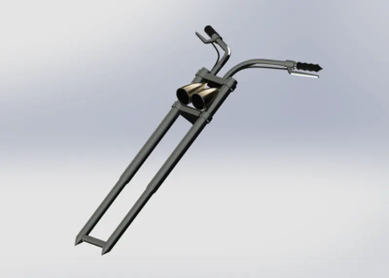
COMMAND USED: Line, sketch, circle, Cut Extrude, Boss Extrude, revolve, Cut revolve, Body move, Projected curve, sweep, combine, mirror, Fillet, Orientation (vertical Plane fork), Dome, Linear Pattern, Plane creation.
PROCEDURE
- Sketch a figure on front plane as in the image.
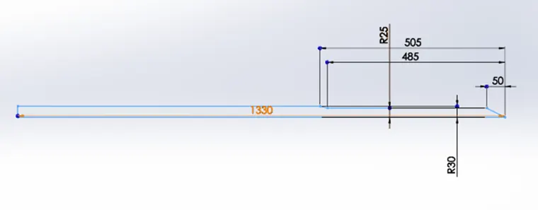
- Revolve the sketch created along the longest side.
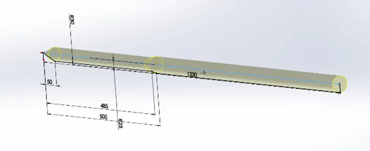
- Create a sketch for clamp on the top of the fork as in image.
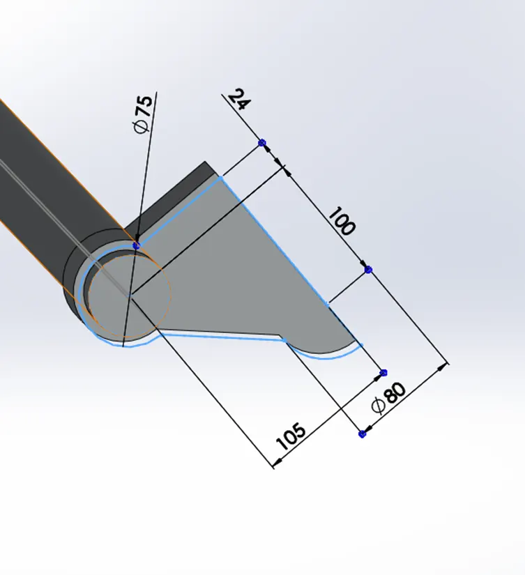
- Extrude the sketch offset towards the fork.
- Apply fillets on the corners.
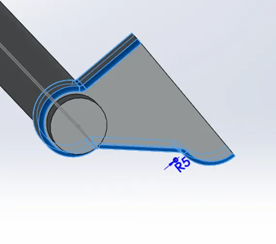
- Make temporary axis visible and use linear pattern to make lower clamp provide a distance.
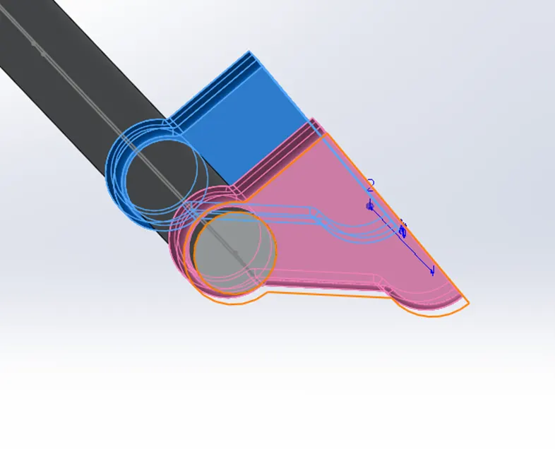
- For mounting, the front wheel create a sketch on fork as seen in the image.
- Merge this section with the fork.
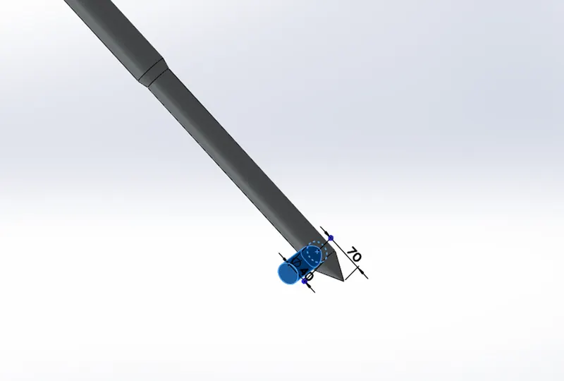
- Create a sketch and extrude it between clamps for mounting the fork to the chassis.
- Sketch on the front plane for headlights as in image.
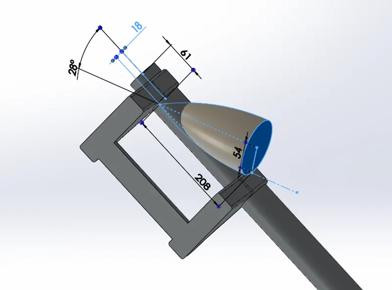
- Revolve the arc along the line.
- Position the head light as required in the design.
- Make a sketch and use revolve cut to provide details to the head light.
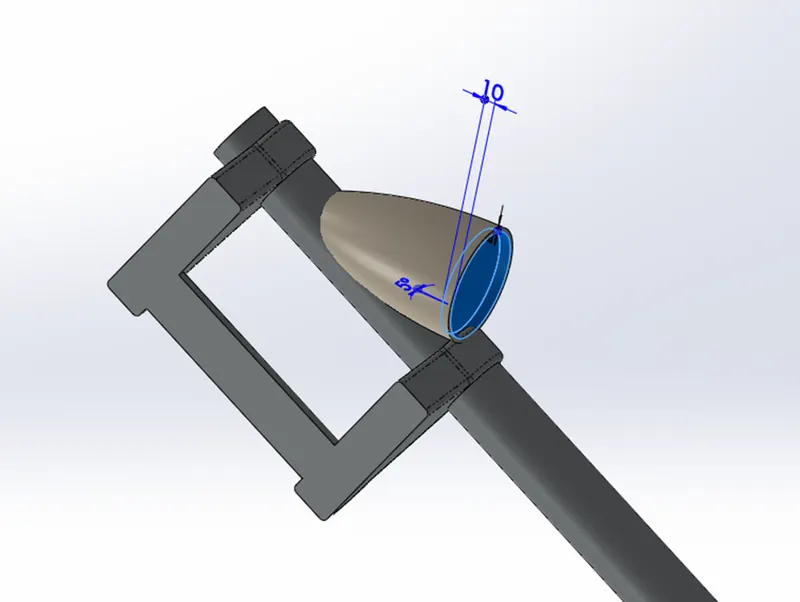
- Make a dome on face of headlight to make it more realistic.
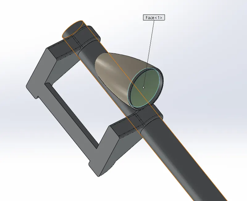
- For handle bar sketch a circle of size of the bar on top of clamp.
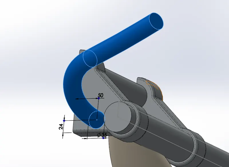
- Sketch a spline for handle bar on top plane and another spline on front plane.
- Produce a projected curve from above sketched two splines.
- Sweep the circle through the projected curve
- At the end of the handle created sketch a figure for grip as shown in image.
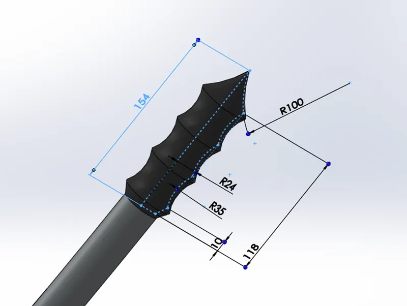
- Use revolve command on the grip sketch
- For brake lever create a new plane provide a reference angle from the plane created for handle bar.
- Make a sketch on this new plane as in image and extrude it.
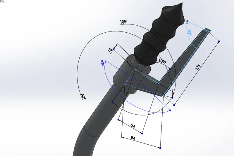
- Apply fillets at sharp corners.
- For cable follow the same procedure which is used to create handle bar with required dimensions.
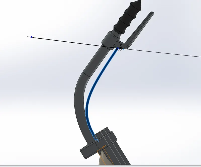
- Use mirror option about the flat face of clamp and use combine bodies.
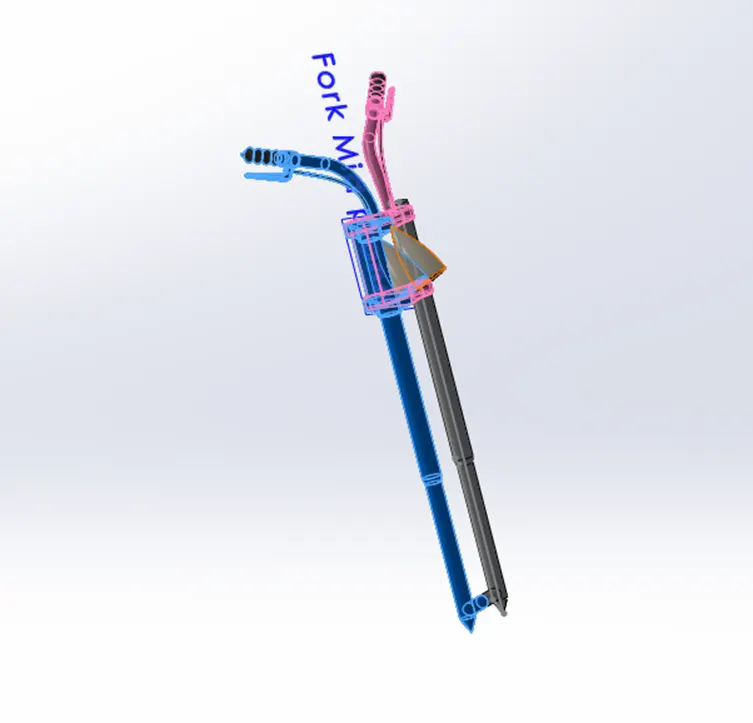
- Apply appearance as required.
- REAR WHEEL
Rear wheel is generally wider but smaller than front wheel for good grip and proper transmission of power for movement of bike. The rear wheel consists of tyre, rim, sprocket, brake assembly etc.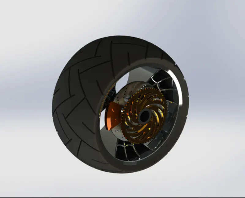
COMMAND USED: Sketch, Line, Spline, Center Line, Revolve, Boss extrude, Cut Extrude, Chamfer, offset entities trim, three-point arc, revolve cut, circular pattern, combine, intersection curve.
PROCEDURE
The process of making is similar to that of front wheel the other parts which we need to create are.
1.Axle for rear wheel.
- Make sketch as shown in the image on the front plane rear wheel.
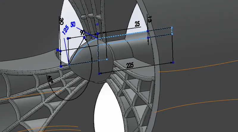
- Revolve the sketch created along the center line for creating axle.
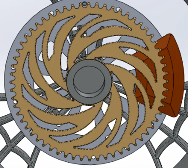
2.sproket for rear wheel.
- Sketch a circle on the face of the axle as shown in image.
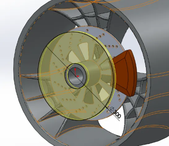
- Extrude the circle blind from the surface.
- Apply chamfer along the circumference of the disk for smooth surface.
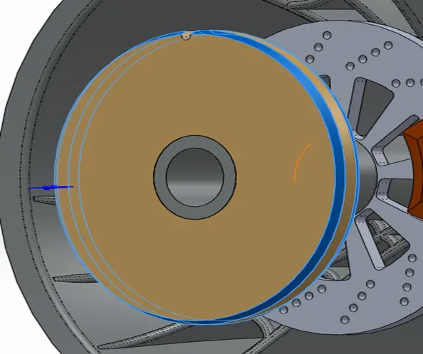
- Sketch a figure as shown in image for making teeth on sprocket for installing chain.
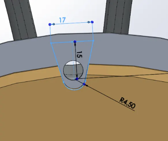
- Use extrude-cut to make teeth and apply fillets for smooth surface.
- Use circular pattern on teeth to get it on whole section.
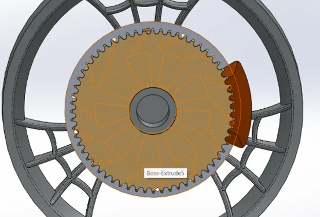
- Now for making slots on the sprocket draw the sketch as shown in figure and use extrude-cut.
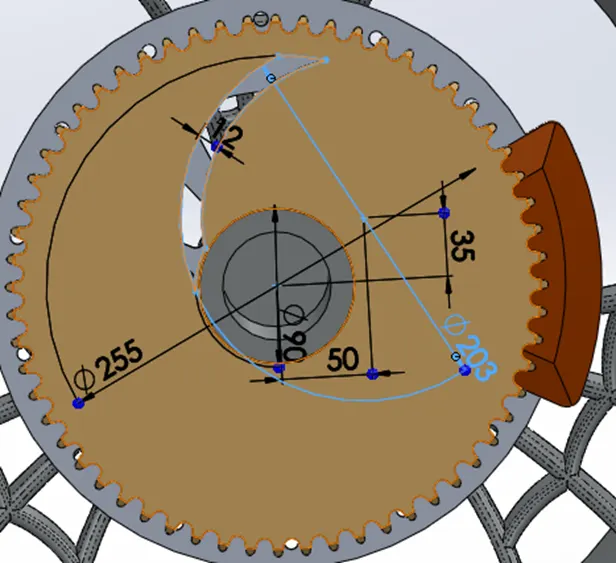
- Use fillets where the lines meet to have a smooth curve.
- Use the circular pattern to replicate the slots created.
- FRONT FENDER
Front fenders are used to prevent any object or liquids to get thrown by rotating wheel, it is placed such that it covers upper and face of tyre which is facing bike frame.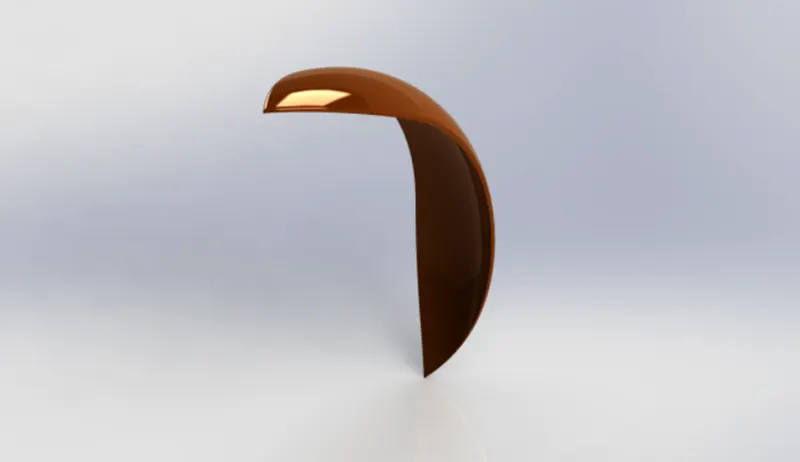
COMMAND USED: Sketch, center line, three-point arc, offset entities, split, revolved boss, Extrude cut, Fillet.
PROCEDURE
- Start by renaming front plane, top plane and right plane as vertical plane front fender, centre plane front fender and mid plane front fender respectively.
- Make a three-point arc and apply a vertical relation between centre of arc and origin and a horizontal relation between end points of arc.
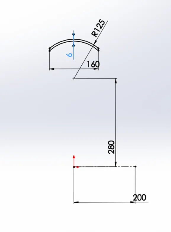
- Apply a vertical distance between centre of arc and origin as required.
- Create an offset of the arc inward.
- Make a vertical line from both end of upper arc to join the lower arc
- Create a horizontal construction line passing through origin
- Revolve the closed arc sketch along the construction line in both directions as required.
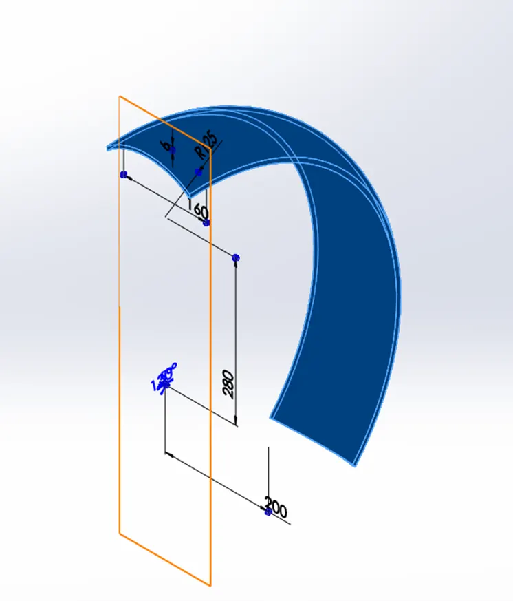
- Make a centre construction line and apply Dynamic mirror entities.
- Sketch a spline with required dimension and use split feature and consume body to make converging section on the fender.
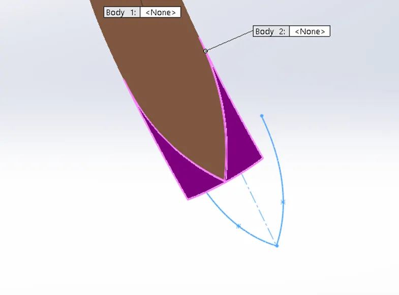
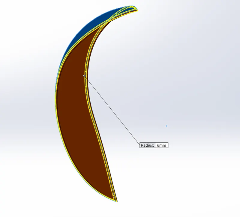
- Repeat the above step to make converging section on another end of the fender.
- Apply fillets and appearance.
- REAR FENDER
Rear fender is provided in the bike to prevent road sprays from being thrown towards bike by rotating wheel. It is placed such that it covers top and the side of wheel which faces bike.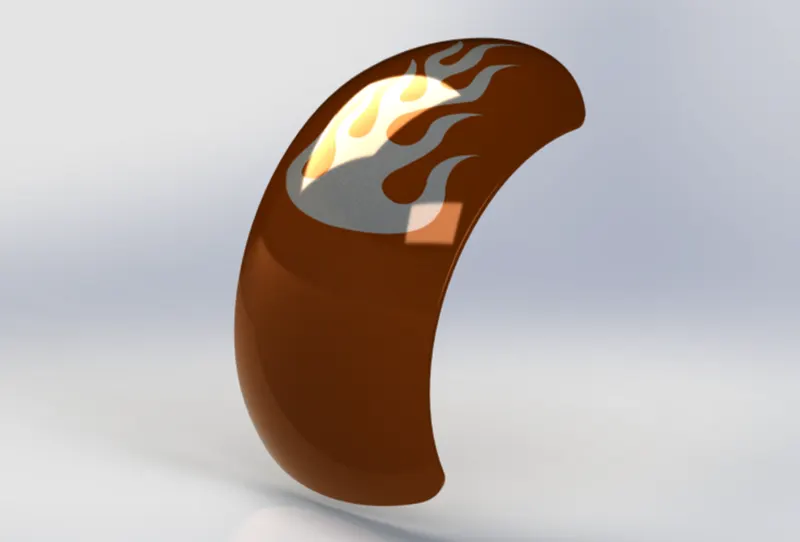
COMMANDS USED: Sketch, center line, three-point arc, offset entities, Trim, revolved boss, Spline, Extrude cut, Fillet,
PROCEDURE
- First rename the Front plane, Top plane, Right plane as Vertical plane rear fender, Center plane rear fender, Mid plane rear fender.
- Make a three-point arc and apply a vertical relation between centre of arc and origin and a horizontal relation between end points of arc.
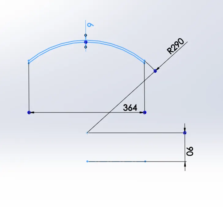
- Apply a vertical distance between centre of arc and origin as required.
- Create an offset of the arc inward.
- Make a vertical line from both end of upper arc to join the lower arc
- Create a horizontal construction line passing through origin
- Revolve the closed arc sketch along the construction line in both directions as required.
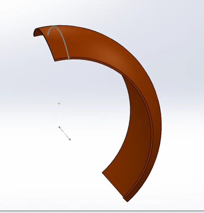
- Make three-point arc on center such that by using split option we could remove a section from one end of fender.
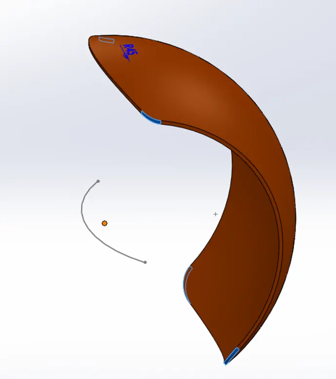
- Apply fillets at four corners of fender and sides of fender.
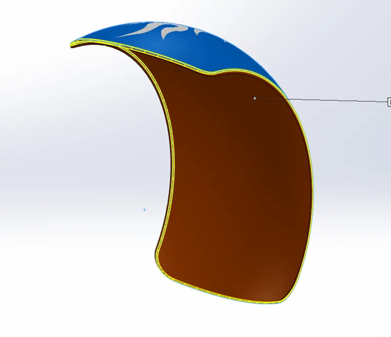
- Use shell feature at inner surface of the fender.
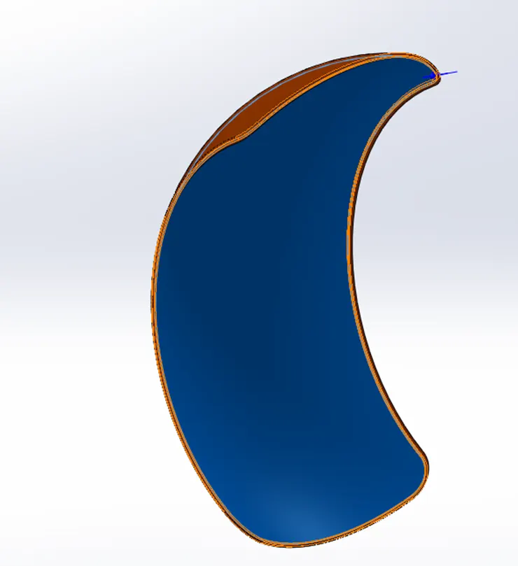
- Apply appearance on the fender.
- FUEL TANK
Fuel tank of the bike is used for safe and cool storage of fuel, the fuel tank of American chopper also used to house a seat for rider.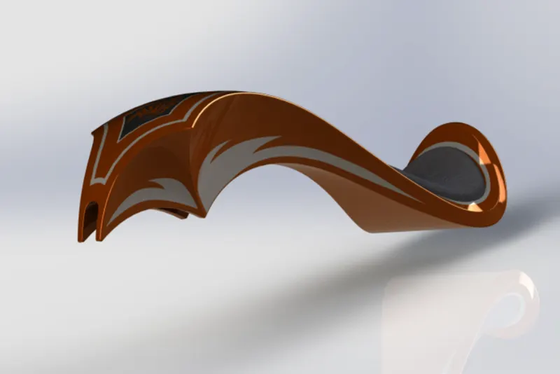
COMMANDS USED: Sketch, Spline, Surface sweep, center line, Surface loft, Projected curve, boundary surface, Surface trim, Surface knit, Split line, Surface extrude, fillet, cut sweep, Mirror, Shell.
PROCEDURE
- Start by renaming the planes front plane, top plane & right plane as mid plane fuel tank, bottom plane fuel tank and front plane fuel tank.
- Open chopper image with proper transparency for reference.
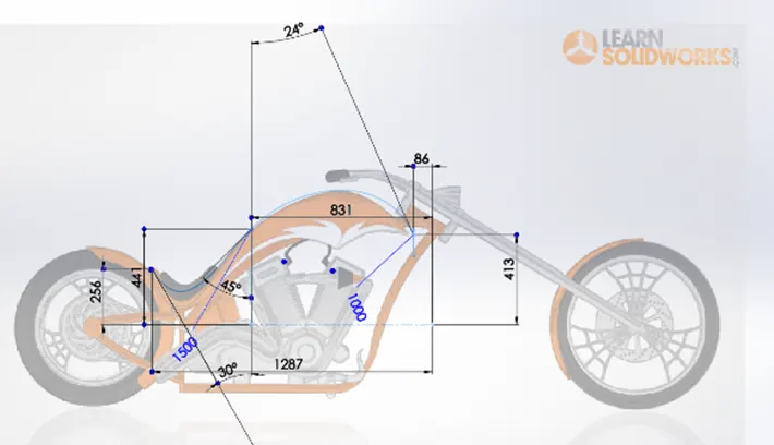
- Create a plane parallel of front plane fuel tank for drawing sketch.
- Draw another sketch on Mid plane fuel tank.
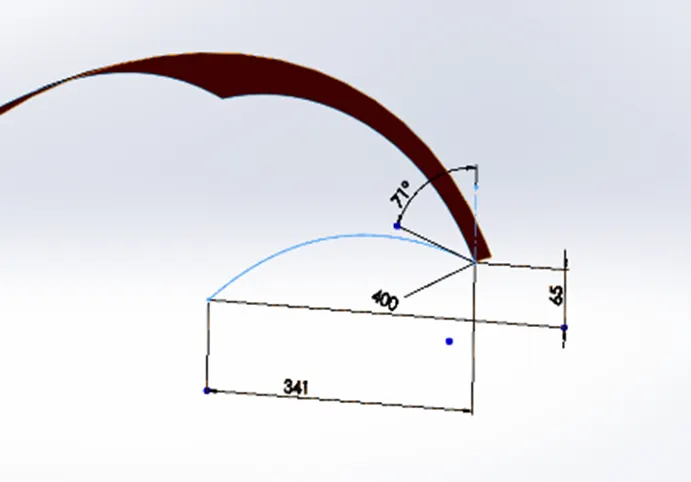
- Make a new plane parallel to the front plane for starting point of the sketch.
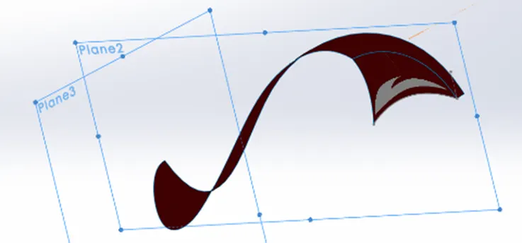
- Draw a spline according to reference picture.
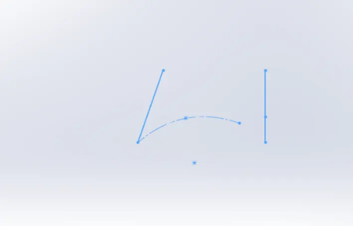
- Use sweep in direction of the mid plane
- Sketch another spline on bottom plane fuel tank
- Create a projected curve, new plane and sketch as per reference image.
- Use surface loft for new sketch.
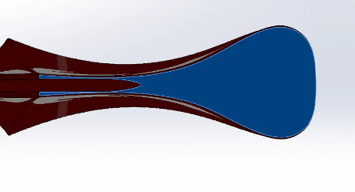
- Create surface of fuel tank by using surface boundary
- Create a sketch on bottom plane for seat.
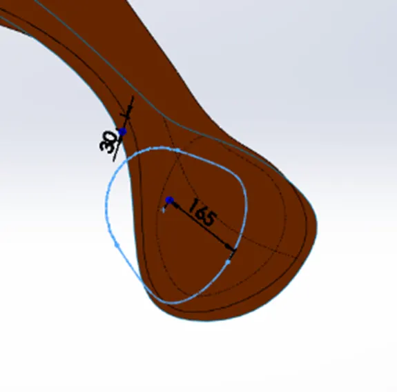
- Use surface extrude for seat and make fillets as required.
- Knit all surfaces together to make it a single part.
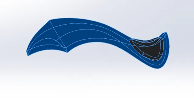
- Use shell command to make the fuel tank hollow.
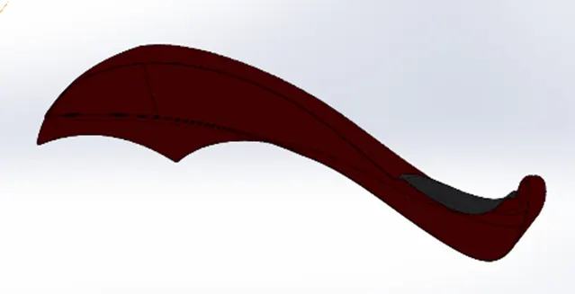
- Apply appearance as required.
- FOOT STEP
Foot step is used by rider to place his/her foot on while riding bike. In American chopper foot step is placed such that the rider has to extend his/her leg forward and sit in an upright position.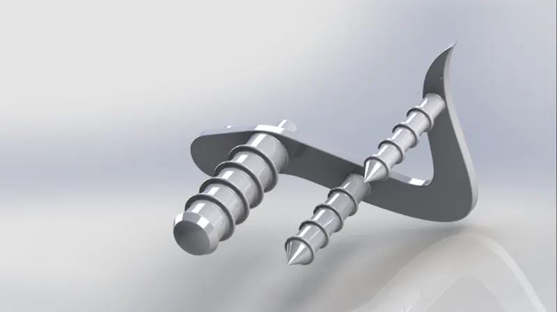
COMMAND USED: Sketch, Spline, Circle, Boss Extrude, Chamfer, Fillet, Linear Pattern, Revolved, Dome.
PROCEDURE
- Create sketch of foot step on front plane using circles, lines fillet spline and apply dimensions as required.
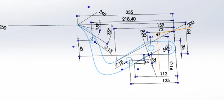
- Extrude the sketches except the circles.
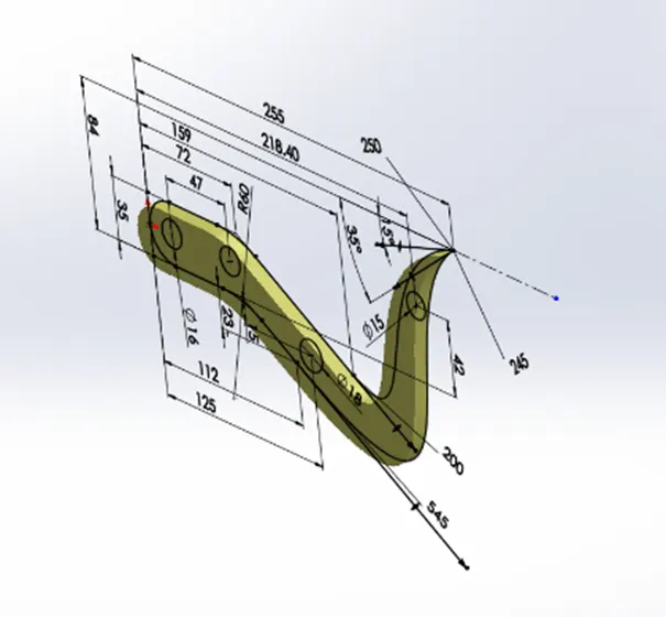
- Extrude the circles in opposite direction for mounting the foot step to the chassis.
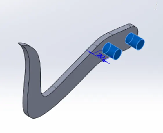
- Create a sketch in the direction opposite to the circles extruded on top plane and use it to revolve command then merge all the section.
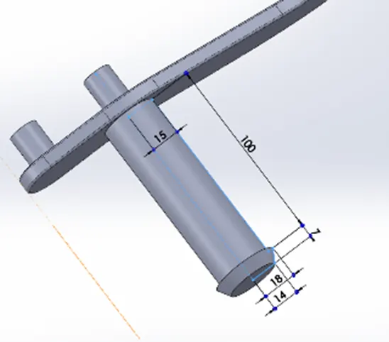
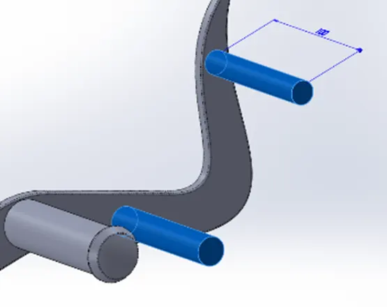
- Make a dome at end of the above sketch created.
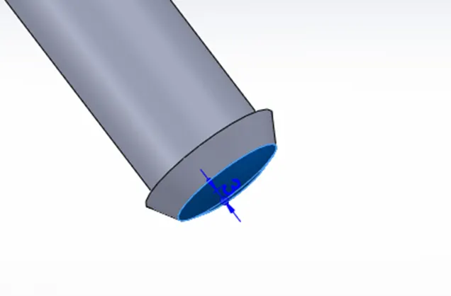
- Apply fillets as required to get a smooth finish.
- Use chamfer distance-distance on revolved and extruded sections.
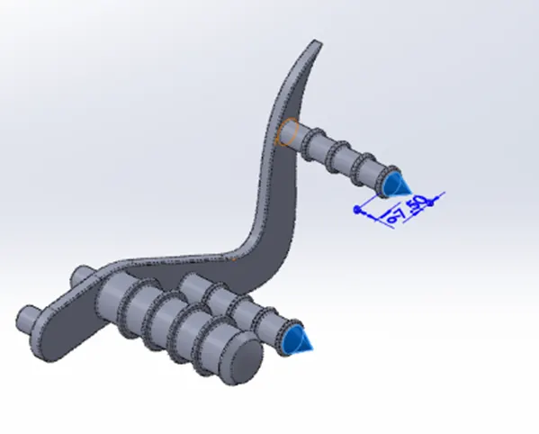
- Offset the circles as in the image.
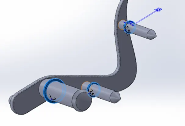
- Extrude the circles with offset from the main surface and apply fillets.
- Apply linear pattern on the offset section created.
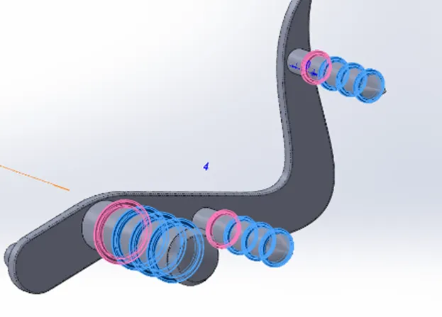
- Apply appearance to the part.
- SIDE STAND
The side stand provides support to the bike while the bike is in the rest position. A side stand should be designed such that it could bear the weight of the bike.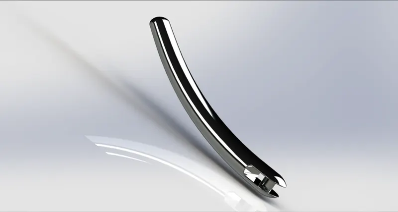
COMMAND USED: Sketch, ellipse, Spline, Loft, split, Cut Extrude, Boss Extrude, Fillet, Dome.
PROCEDURE
- Sketch an ellipse on front plane and make the center point coincident with the origin.
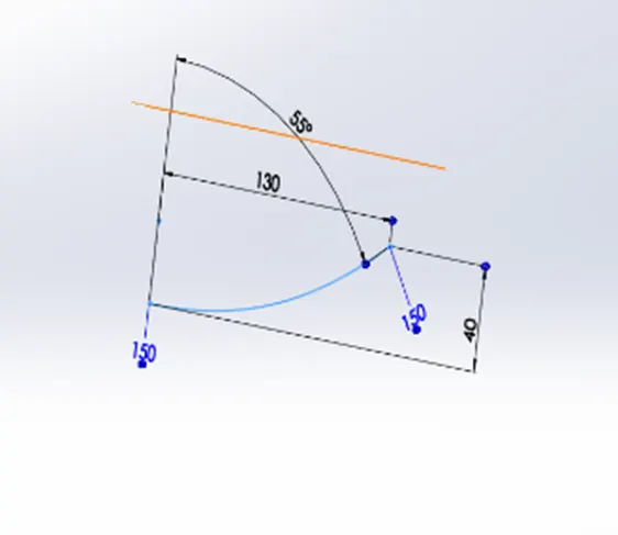
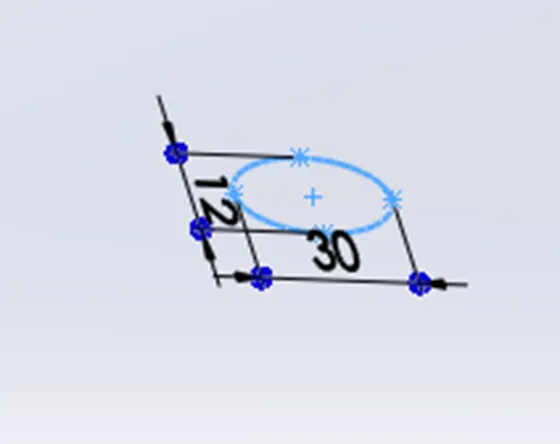
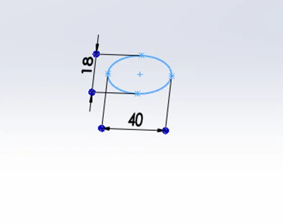
- Draw a spline from the center of the ellipse perpendicular to it and provide proper weight.
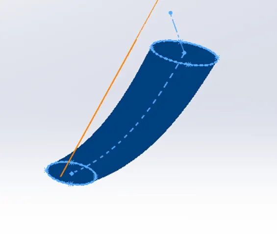
- Create a plane at the other end of the spline which will be perpendicular to the spline
- Make pierce relation between ellipse and spline.
- Use centerline loft by making spline as the center line and ellipse as reference.
- Make a dome at both ends.
- Create a rectangle and use it to cut extrude on one dome.
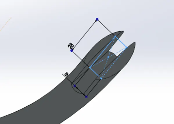
- Create a circle in between the cut section and extrude it by using “Up to next” option.
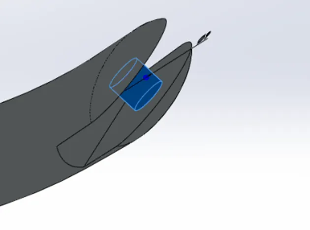
- Make a line and use split option to create flat surface at end having small dome.

- Apply fillets as in the below image.
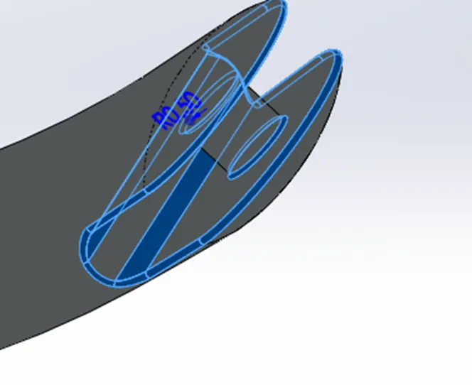
- Apply appearance to the side stand.
- TRANSMISSION BELT
The transmission belt in the bike is used to transmit power from one shaft to another. This belt should have less slippage and long life. 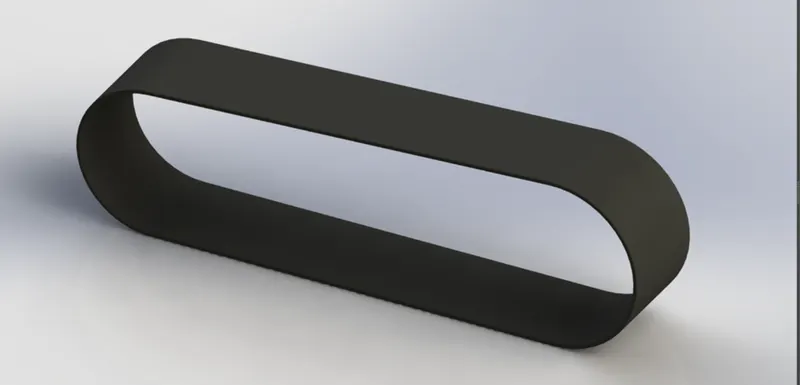
COMMAND USED: Sketch, Line Circle, Offset Entities, Trim, Boss Extrude, Fillet.
PROCEDURE
- Create a sketch on the front plane as in the image.
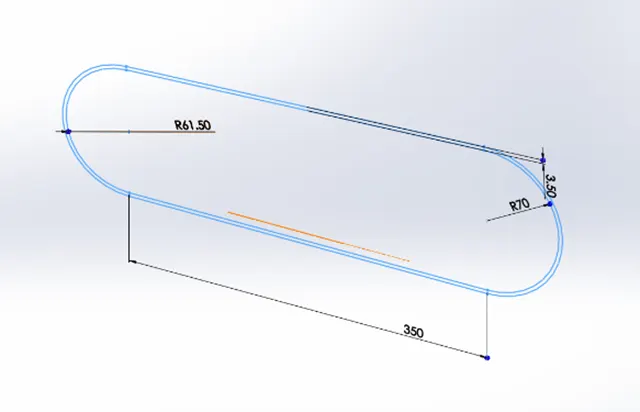
- For sketch draw two three-point arc both in opposite direction.
- Apply horizontal relation between the centers of two arcs.
- Sketch lines joining the arcs and make them tangent at both ends.
- Use offset option on whole sketch.
- Now extrude the sketch as required.
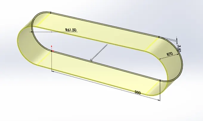
- Apply fillets at the sharp edges.
- Apply appearance.
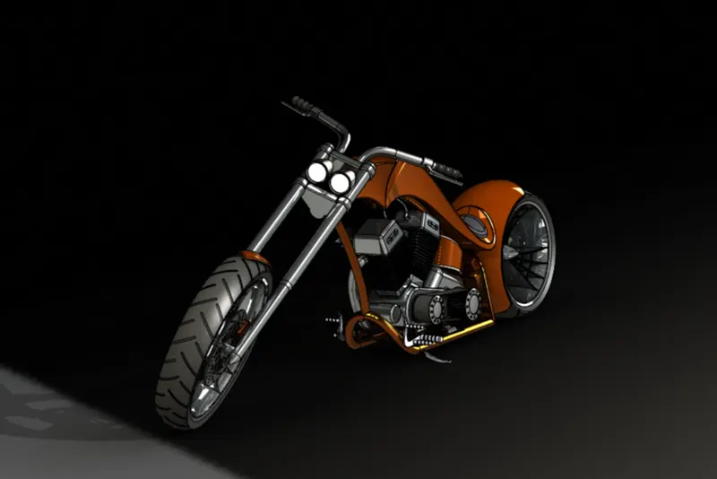
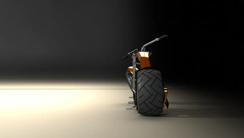
Assembly Of American Chopper
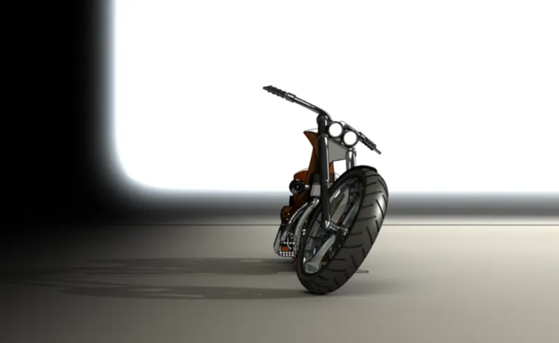
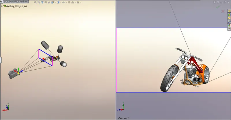
Setting Up Camera
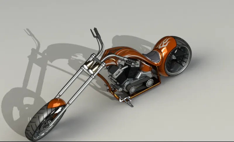
Applying Decals
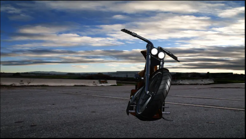
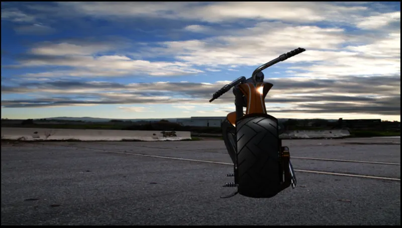
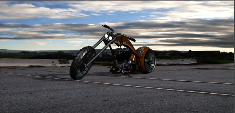
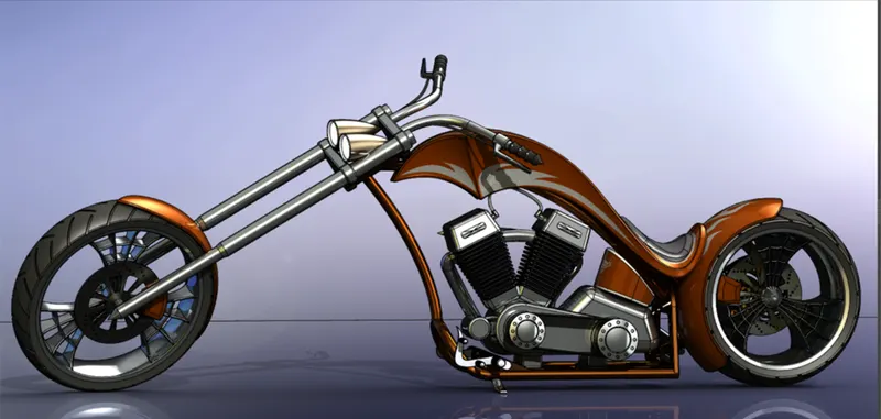 Rendering Of American Chopper
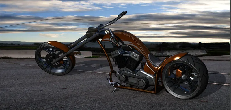
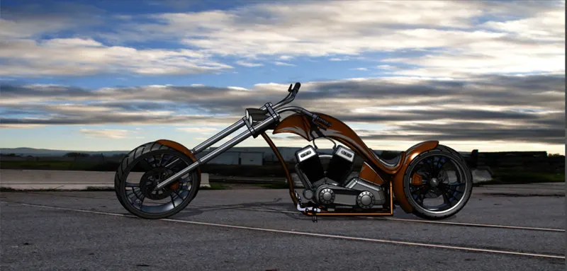
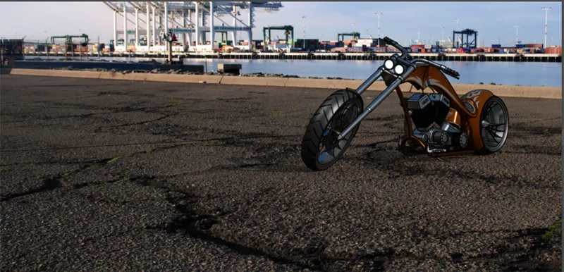
A brief explanation of Commands used to model Parts
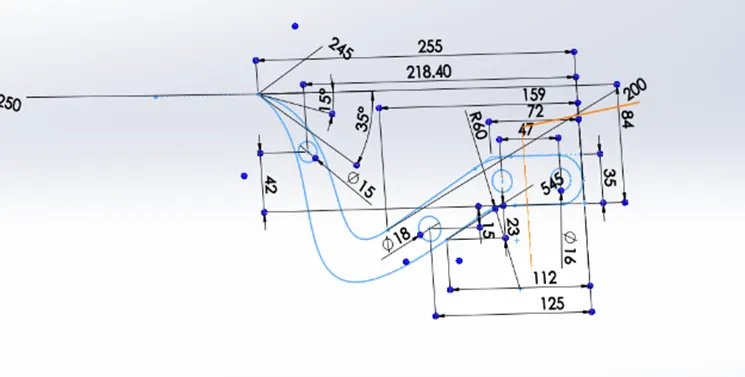
- 2D SKETCH
A Geometry can be created using 2D sketch, this sketch can be controlled by various relations (collinear, Parallel, concentric, Dimension and so on). 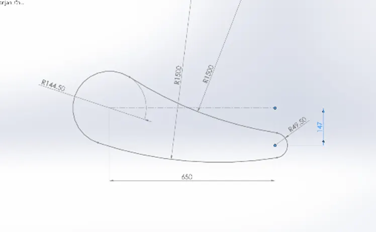
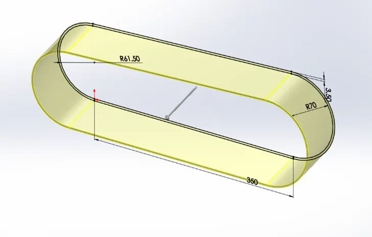
- EXTRUDE
It creates a 3D solid from a enclosed sketch or 3D Surface from an open object. In a specified direction from the selected plane.
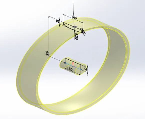
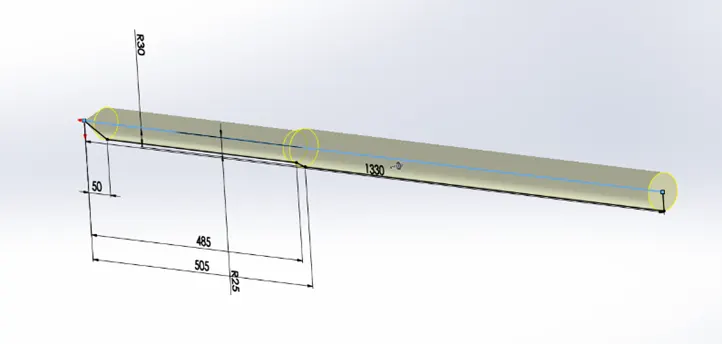
- REVOLVE
This command is used to revolve a profile around a reference line.
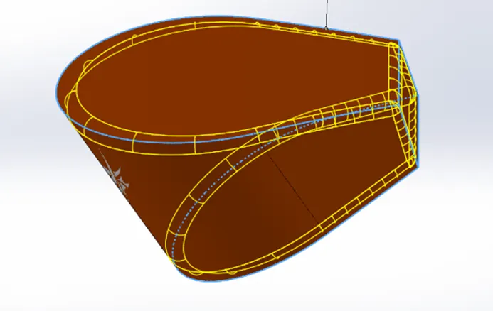
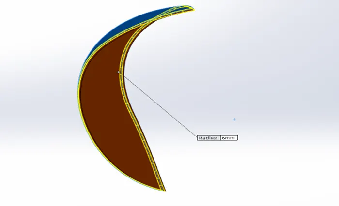
- FILLET
This command rounds one or more edges of a part between two surfaces.
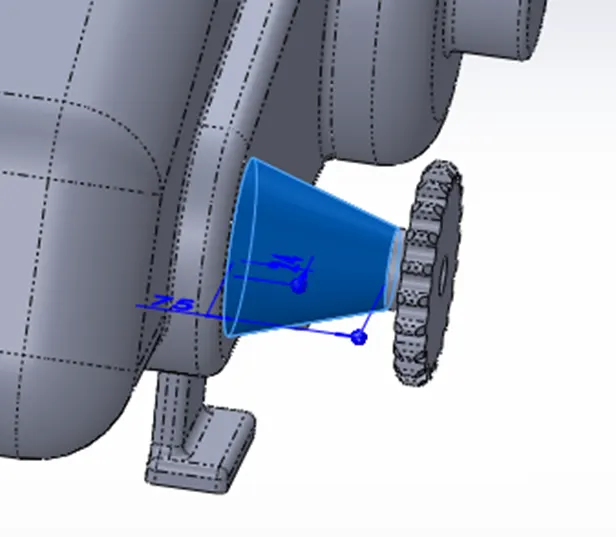
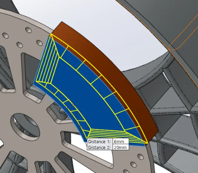
- CHAMFER
This command creates a sloped corner at the edges or between two surfaces
- CUT EXTRUDE
This Command removes a section extruded from an earlier made part
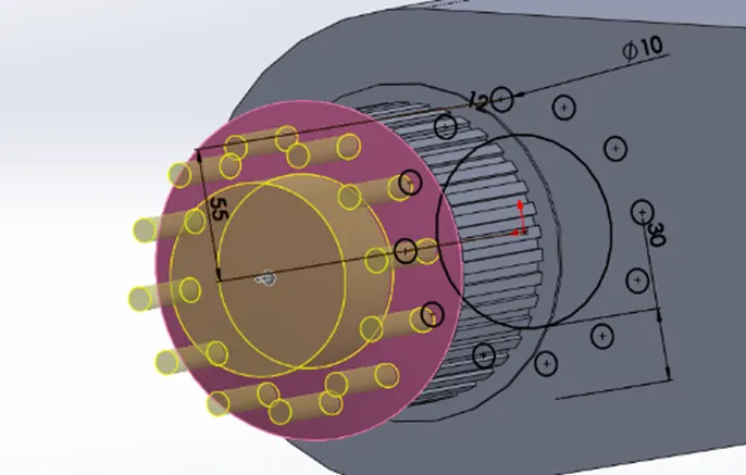
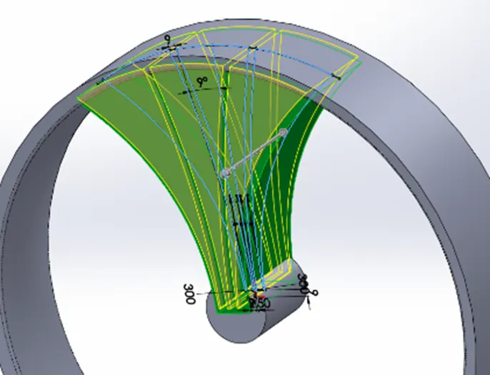
- DOME
This command is used to make dome on any surface.
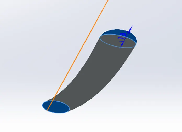
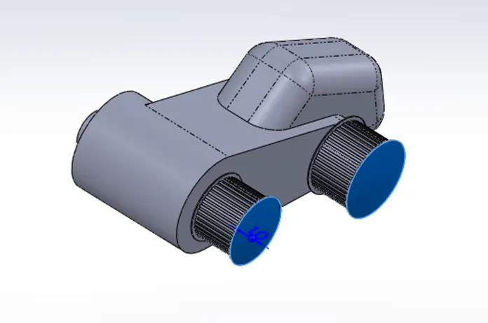
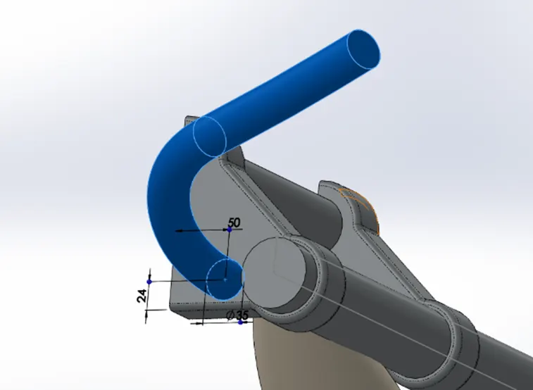
- SWEEP
This feature is used to sweep a profile along with open or closed path.
- SPLINE
Spline is same as polyline but it is used to make smooth curve between two or more points. 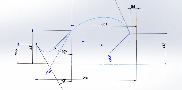
- TRIM
This command removes unwanted section in 2D sketch
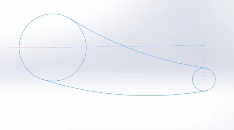
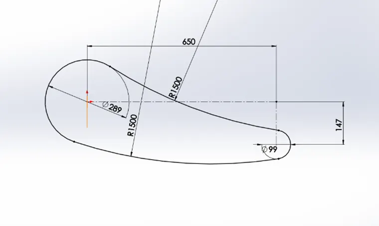
- SHELL
This command is used to make a hollow section inside a part.
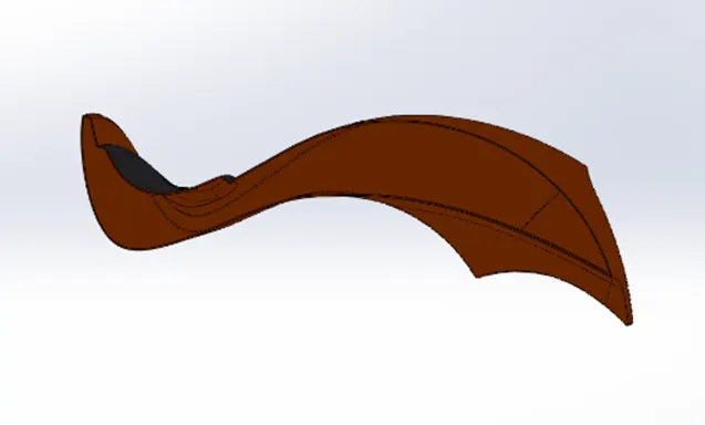
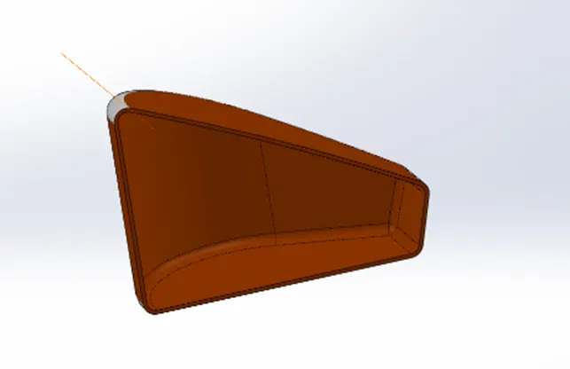
- CIRCULAR PATTERN
This command is used to reduce the time and efforts required to make same part/sketch which is to be replicated number of times in a defined path.
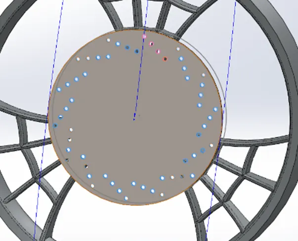
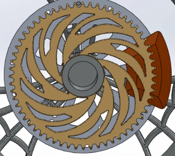
- COMBINE
With the help of this command one can combine multiple bodies to make it a single body or one can add, remove or keep material that is common in the selected parts.
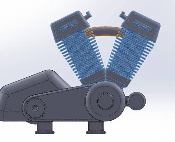
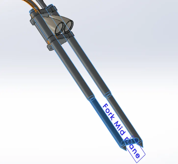
- MIRROR
Mirror command is used to make a replica of the part or a section of part.
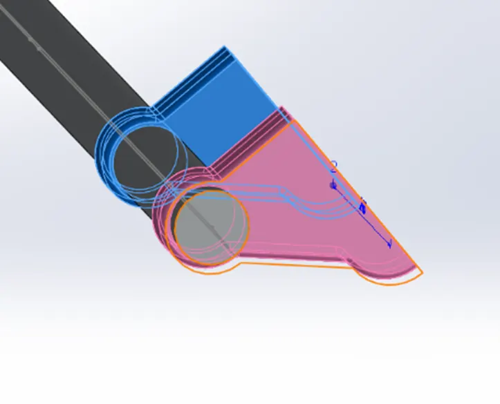
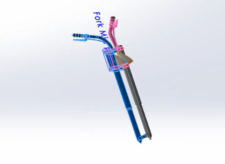
- PROJECTED CURVE
This Command is used to make a intersection curve of two projected sketches.
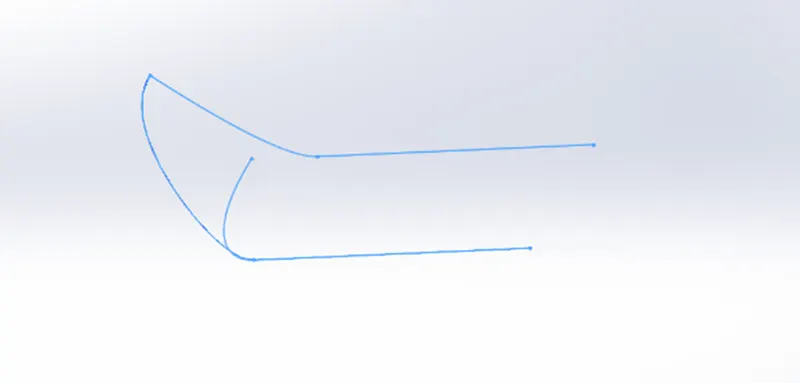
- SPLIT
This command is used to section a single part in two.
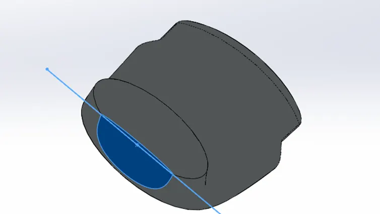
- SURFACE LOFT
This feature is used to create a shape by making transitions between multiple profiles. 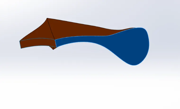
- SWEPT SURFACE
This command is used to generate a section along a path. 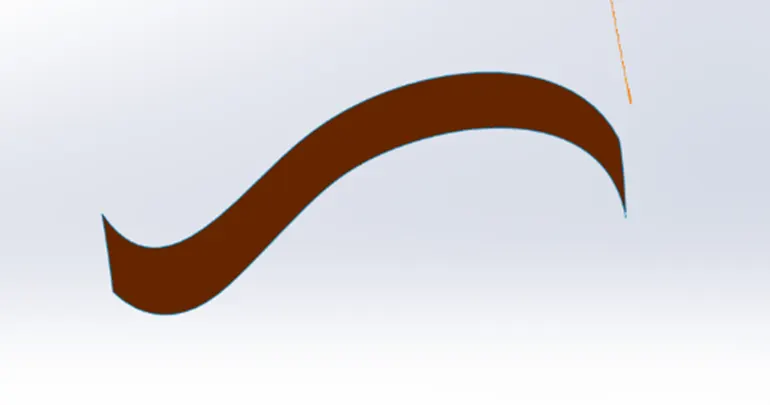
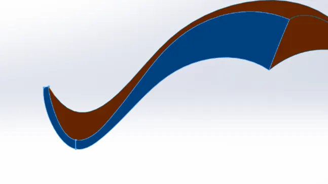
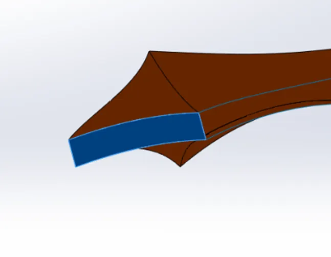
- BOUNDARY SURFACE
This command creates a surface tangent or curvature continuous in all sides of the surface.
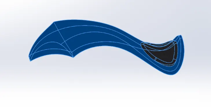
- KNIT SURFACE
This command is used to knit two or more surfaces into one surface.
MATES
- PARALLEL MATE
This command is used to have a constant distance between either edges, parts or surfaces. 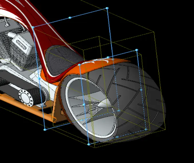
- CONCENTRIC MATE
This command places two cylindrical, spherical or conical parts in a common center line. 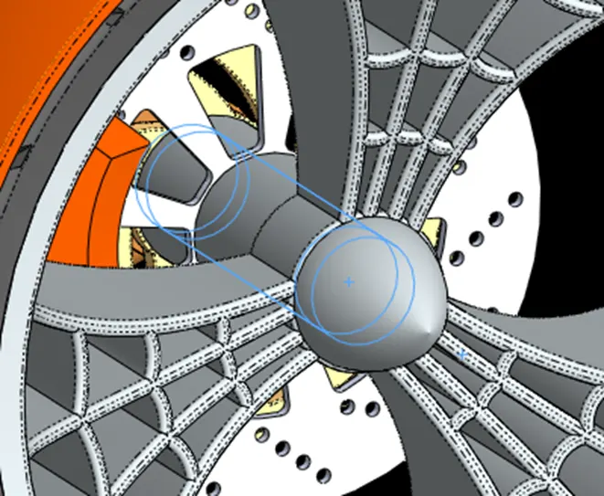
- ANGLE MATE
This command is used to have an inclined relation between two or more parts. 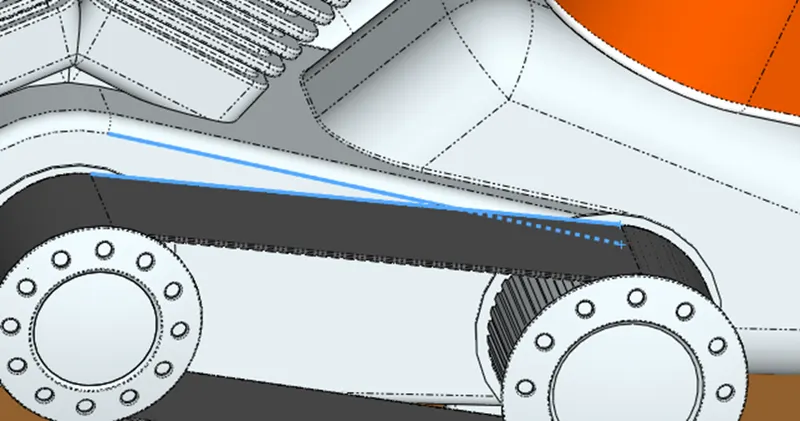
- COINCIDENT MATE
This is mate between two parts that is needed to coincide with each other. 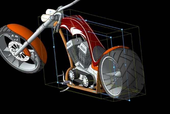
- DISTANCE MATE
This command is used to have a fixed distance relation between two surfaces/points of parts. 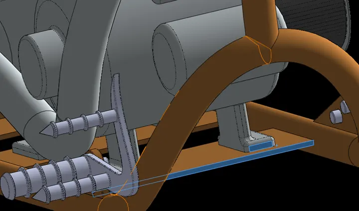
- WIDTH MATE
This command constrains a tab between two planer faces. 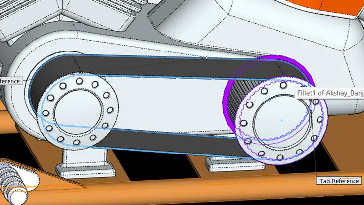
- LIMIT ANGLE MATE
This command is used to limit a part's movement with respect to other parts or surfaces. 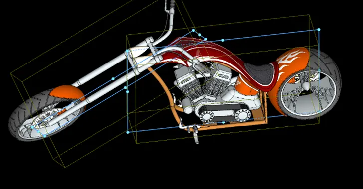
- POSITION MATE
This command is used to fix the position of a particular part with respect to another part or plane. 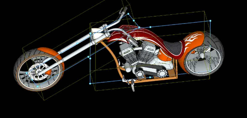
- TANGENT MATE
This command is used when we need an inclination constraint between two surfaces or parts. 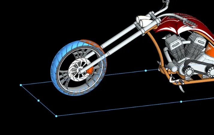
Steps to make parts of American chopper
- Select a new part file.
- Select a plane as required.
- Sketch as per the design.
- Solid modelling / Surface Modelling.
- Detailing (Fillet / chamfer).
- Save the part created.
Steps to Assemble American Chopper
- Open New part assembly file
- Select a plane as required
- Fix any one part (Which will be reference for other Parts)
- Assemble other parts by using various mate option
- Adding Decals
- Setting up headlights
- Save the assembled chopper
- Rendering of American chopper
- Setting up background
- Setting up Lights
- Setting up Cameras
(Note: To make the American chopper realistic use Photo view 360)
CONCLUSION
Successful completion of Modelling, Assembling, and rendering of American Chopper
In Solid works.