Radar Mast & Final Assembly of Yacht
RADAR MAST
FEATURES USED:
- Reference Geomery - Plane
- Boss/Base Extrude
- Boss/Base Revolve
- Boss/Base Sweep
- Mirror
- Dome
- Shell
- Chamfer
- Fillet
SKETCH FEATURES:
- Line
- Spline
- Center Line
- Center Point Arc
- Circle
- Projected Curve
- Rectangle
- Slot
Images:
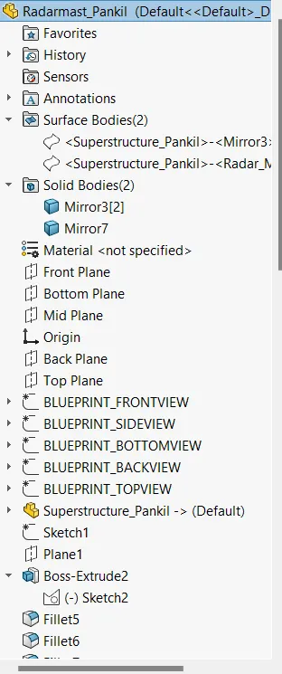
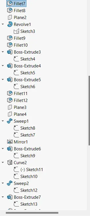
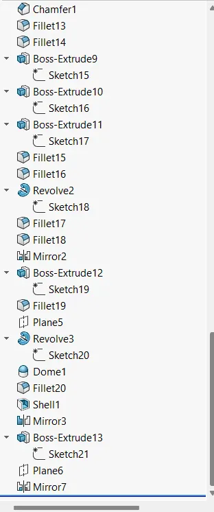
(Feature tree of the Radar Mast)
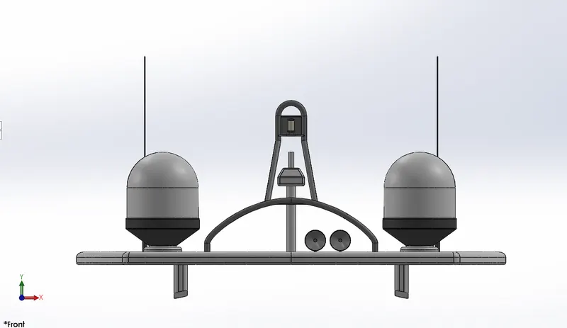
(Front view of the Radar Mast)
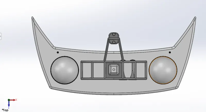
(Top view of the Radar Mast)
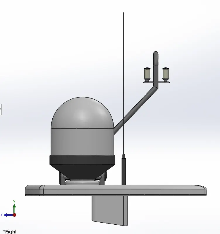
(Right side view of the Radar Mast)
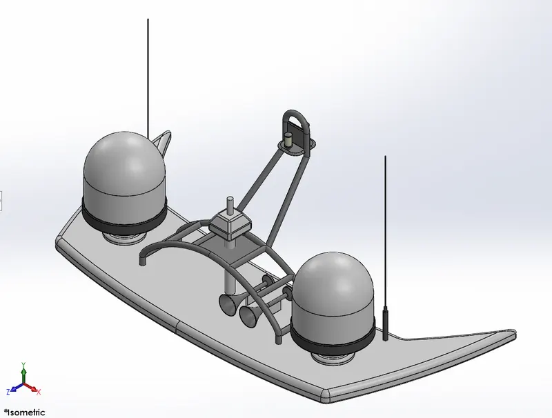
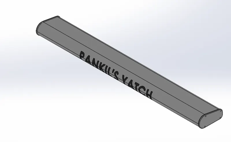
(Isometric view of the Radar Mast)
> FINAL PROJECT REPORT
SUNSEEKER PREDATOR YACHT
AIM
- To learn about different features of solidworks in solid modelling and surface modelling to create a 3D model of a Sunseeker Predator Yacht.
OBJECTIVES
- To learn about surface modelling and solid modelling to create different parts of the yacht.
- To create assembly of the yacht.
- To learn about Photoview 360 to do photo realistic renedering of the yacht.
INTRODUCTION
A Solidworks model consists of 3D solid geometry in a part or assembly documents. Drawings are created from models or by drafting views in a drawing document. Typically, begin with a sketch, create a base feature and then add more features to the model.
In this project we will discuss about the design approach and different features of the solid modelling and surface modelling.
> Solid Modelling
- Solid modelling is the process of constructing a 3D model through a series of additive and subtractive operations while always maintaining a calculable volume.
> Surface Modelling
- Surface modelling is the process of constructing a 3D model through the process of defining each of the faces that are present in its geometry.
DESIGN APPROACH
> There are mainly 2 types of approaches.
1. Top-down Approach
This is also known as stepwise design. This is a system design approach where design starts from the system as a whole. Complete system is then divided into smaller sub-applications with more details.
2. Bottom-up Approach
This is a system design approach where parts of the system are defined in details. Once these parts are designed and developed, then these parts or components are linked together to prepare a bigger component. This approach is repeated until the complete system is built.
DESIGN METHODOLOGY
Setup the blueprints of the model
↓
Create 2D sketch
↓
Apply Solid/Surface features to convert it into 3D model
↓
Create all the parts of the model
↓
Assemble all the parts to complete the model
↓
Apply appearances, lighting and decals
↓
Use Photoview 360 to make photorealistic rendering of the model
DIFFERENT FEATURES USED TO CREATE A YACHT
> Sketch Features
- Point
- Line
- Spline
- Center Line
- Circle
- Arc
- Rectangle
- 3D Sketch
- Polygon
- Straight Slot
- Convert Entities
- Offset Entities
- Spilt Entities
- Projected Curve
- Linear Pattern
- Sketch Pattern
- Sketch Fillet
- Trim and Extend
- Projected Split Line
- Text
> 3D Modelling Features
- Boss/Base Extrude
It is used to extend a sketched profile in one or two directions as either a thin feature or a solid feature.
- Boss/Base Revolve
It is used to create a solid model around an axis. It is used to revolve the sketch around an axis to add material to it.
- Boss/Base Loft
Loft creates a feature by making transitions between profiles. Loft can be created by using two or more profiles.
- Boss/Base Sweep
This is the one feature that help sweep a closed profile along a closed or open path.
- Boss/Base Thicken
It is used to create a solid feature by thickening one or more adjacent surfaces.
- Cut Extrude
Cut extrude feature removes material from the part.
- Circular Pattern
Circular pattern is used to create multiple instances of one or more features that can be space uniformly around an axis.
- Mirror
It is used to create a copy of a feature or multiple features, mirrored about a face or a plane.
- Dome
It creates a dome that is tangent to the adjacent cylindrical or conical face.
- Shell
The shell tool hollows out a part, leaves selected faces open and creates thin walled features on the remaining faces.
- Split
Split feature is used to create multiple parts from an existing part.
- Chamfer
The chamfer tool creates a bevelled feature on selected edges, faces or a vertex.
- Fillet
It creates a rounded internal or external face on one or more edges of a part, between two face sets or between three adjacent face sets.
> Surface Modelling Features
- Surface Loft
Loft surfaces are surfaces generated by multple curves or existing edges creating a smooth tangency between the selected curves. This tool is very valuable for modelling complex surfaces.
- Surface Sweep
Sweep surfaces are surfaces that are generated from a section curve positioned along a path.
- Surface Extrude
Surface extrude is used to extrude the boundary edges of a face of a solid body or edges of a surface body in a customized direction.
- Ruled Surface
The ruled surface command creates surfaces that extent out in a specified direction from selected edges.
- Surface Extend
Surface extend command is used to extend a surface by selecting an edge, multiple edges or a face.
- Surface Fill
This feature constructs a surface patch with any number of sides, within a boundary defined by existing model edges, sketches, or curves, including composite curve.
- Surface Knit
Surface knit is used to combine two or more faces and surfaces into one.
- Surface Offset
Surface offset tool creates a new surface body from an existing set of faces.
- Surface Trim
Surface trim is used to trim unwanted surfaces. That surface must be intersecting with any surface, plane or has a sketch on its face.
PART MODELLING
> Main parts of the Sunseeker Predator Yacht
- Propeller
- Radar
- Hull
- Garage Door
- Superstructure
- Front seat
- Middle seat
- Rear seat
- Radar mast
> BLUEPRINT SETUP
- Blueprint is a guide for making something. It is a design or pattern that can be followed.
- To setup the blueprints in solidworks, follow these steps:
- Open Solidworks.
- Create new part file.
- Select any plane and create new sketch, then go to Tools > Sketch tools > Sketch picture, then browse the image respected to the selected plane.
- Change the different properties like dimensions, position and transparency as required and then close the sketch.
- Images:
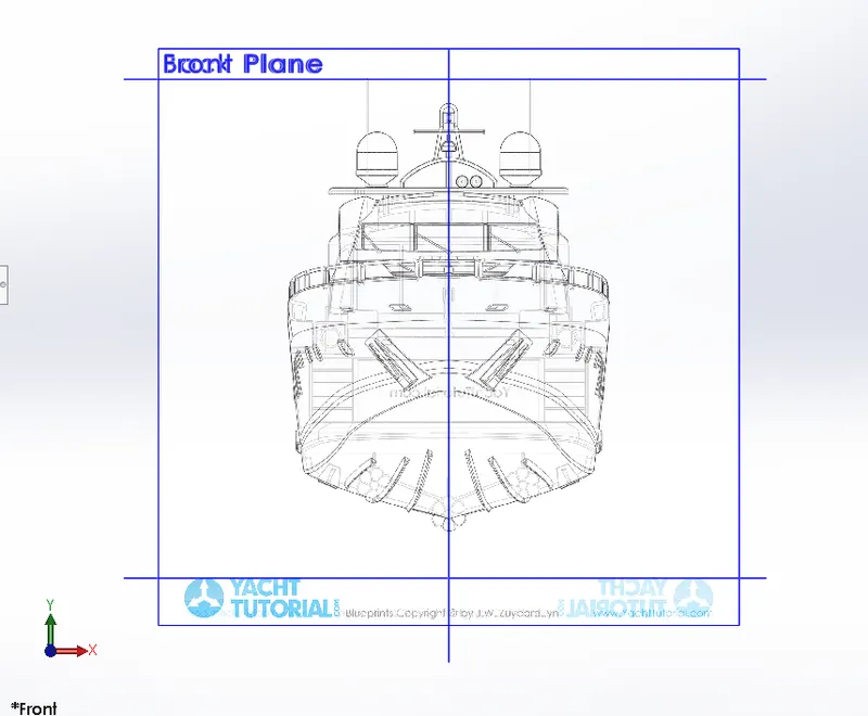
( Front view of the Blueprint)
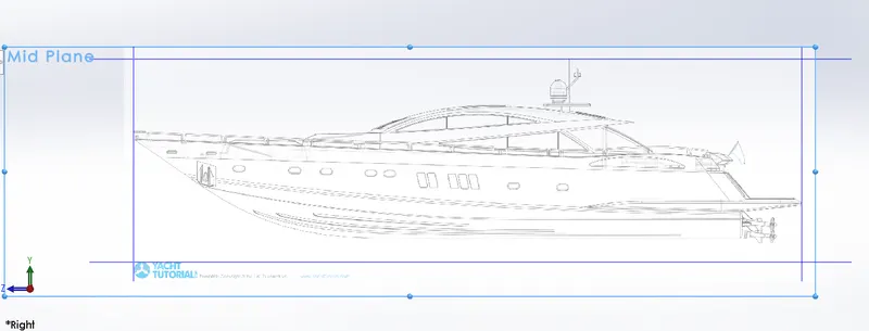
(Right side view of the Blueprint)
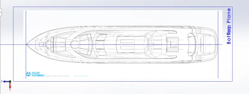
(Top view of the Blueprint)
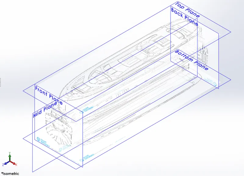
(Isometric view of the Blueprint)
1. Propeller
- Propellers are used to create thrust to propel a boat through water.
- Features used to create propeller in solidworks:
- Boss/Base Revolve
- Boss/Base Loft
- Cut Extrude
- Circular pattern
- Fillet
- Images:
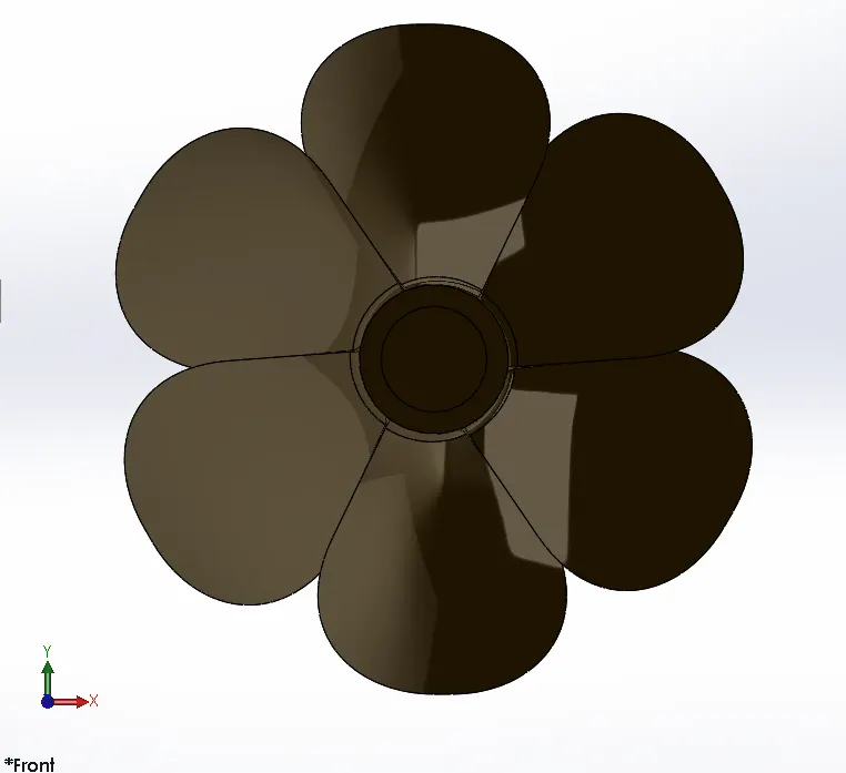
(Front view of the Propeller)
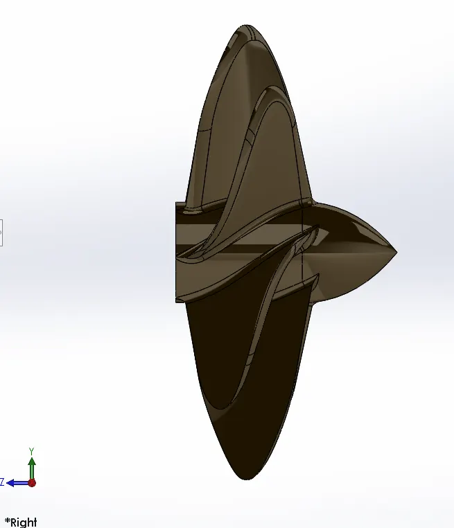
(Right side view of the Propeller)
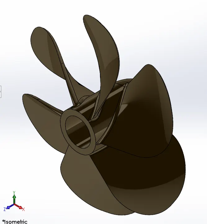
(Isometric view of the Propeller)
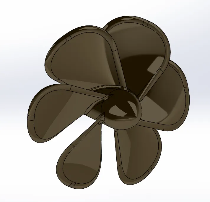
(Propeller)
2. Radar
- A radar device acts as a major navigation aid for boaters. It helps in detecting boats, birds, landmasses and weather systems even if the visibilty is less than usual.
- Features used to create radar in solidworks:
- Boss/Base Extrude
- Cut Extrude
- Sketch Driven Pattern
- Mirror
- Fillet
- Images:
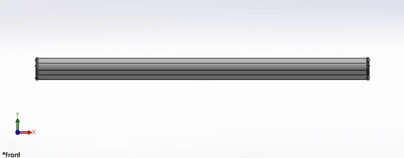
(Front view of the Radar)
(Isometric view of the Radar)
3. Hull
- The hull of a yacht is the most notable structural entity of the yacht. To define the hull, it can be said that it is the watertight enclosure of the yacht, which protects the cargo, machinery, and accommodation spaces of the yacht from the weather, flooding and structural damage.
- Features used to create hull in solidworks:
- Surface Loft
- Surface Trim
- Surface Extrude
- Surface Knit
- Surface Fill
- Reference Geometry - Plane
- Shell
- Boss/Base Extrude
- Boss/Base Revolve
- Boss/Base Sweep
- Cut Extrude
- Dome
- Delete Face
- Mirror
- Chamfer
- Fillet
- Images:
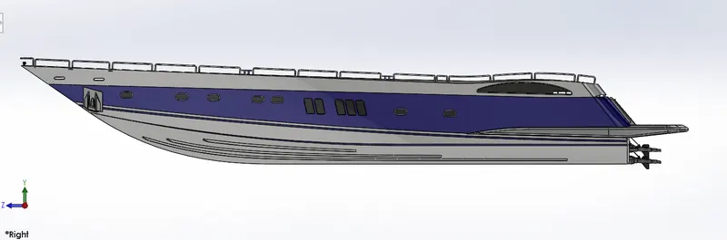
(Right side view of the Hull)
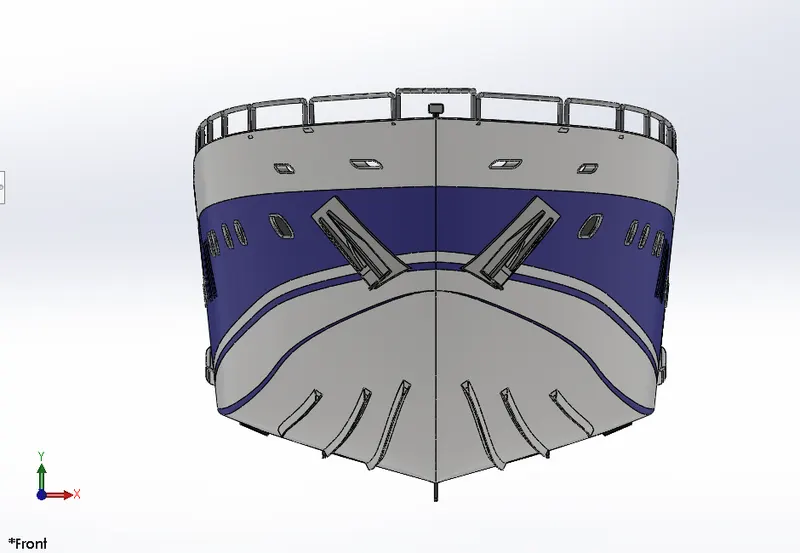
(Front view of the Hull)
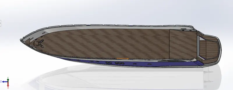
(Top view of the Hull)
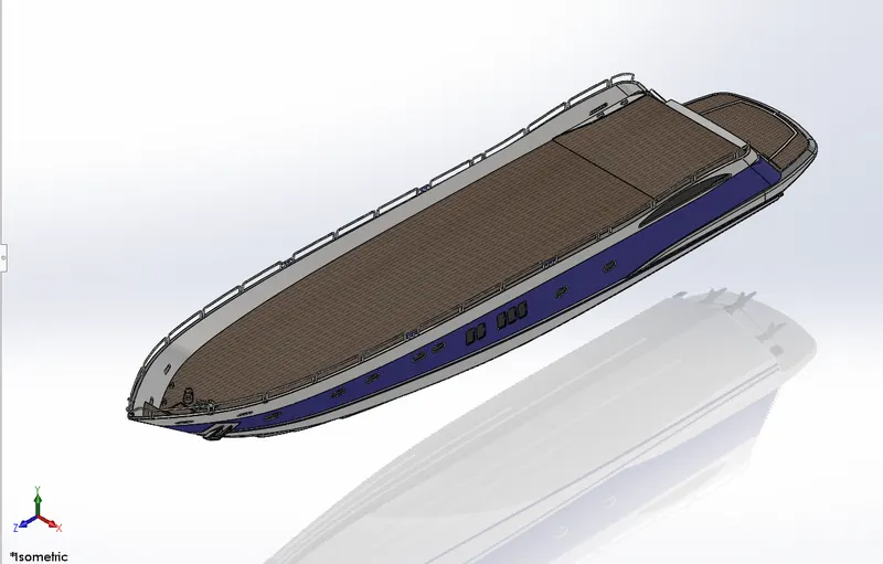
(Isometric view of the Hull)
4. Garage Door
- A garage door is a large door on a garage that opens either manually or by an electric motor. Garage doors are larger enough to accommodate automobiles and other vehicles.
- Features used to create garage door in solidworks:
- Split
- Cut Extrude
- Shell
- Mirror
- Fillet
- Images:
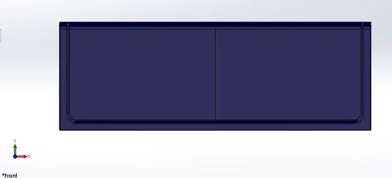
(Front view of the Garage door)
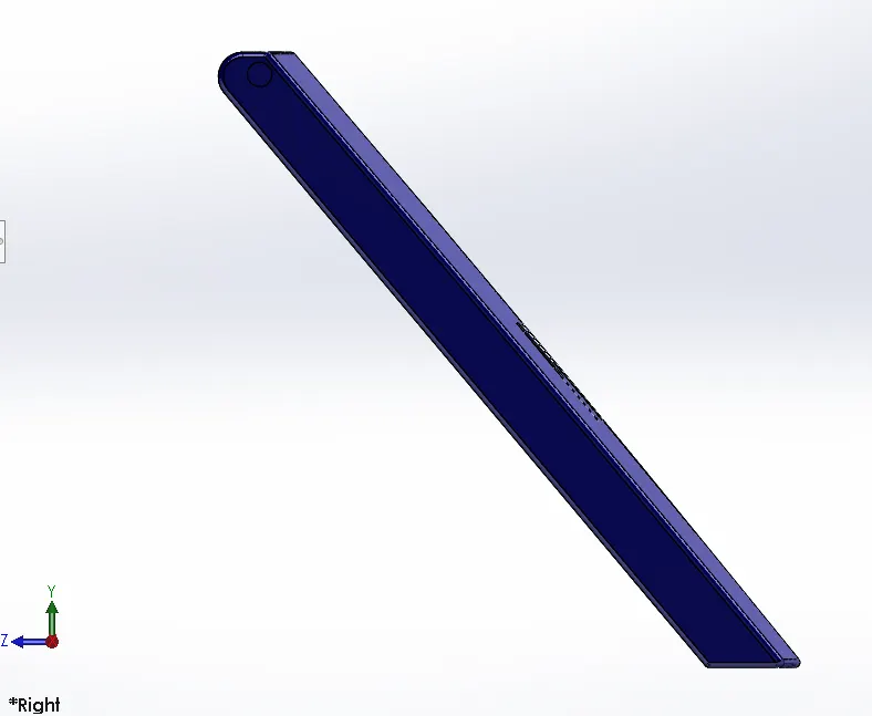
(Right side view of the Garage door)
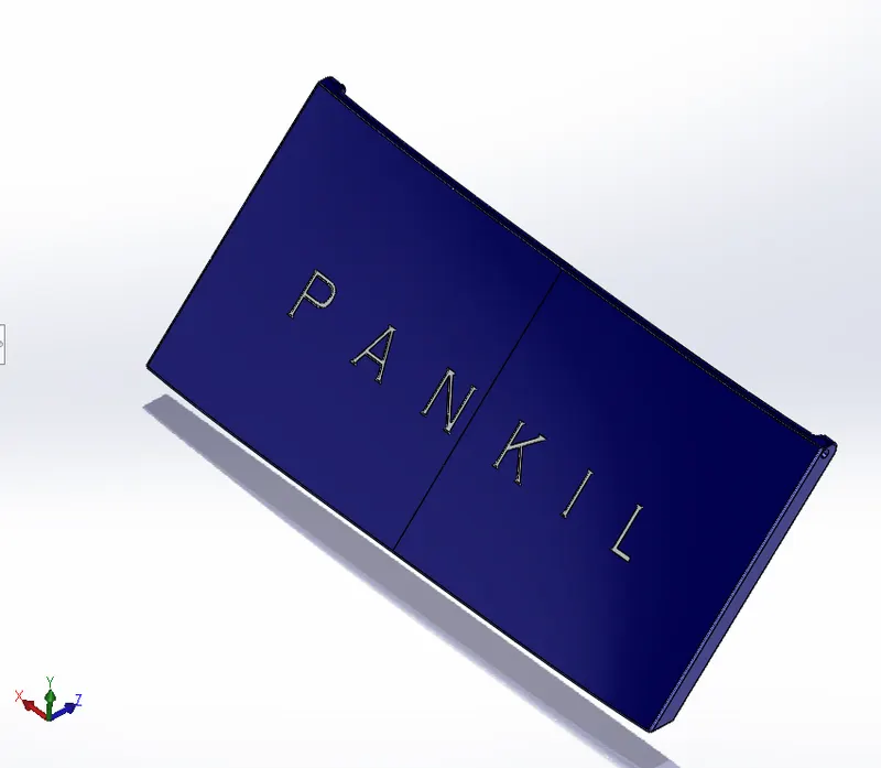
(Garage Door)
5. Superstructure
- A superstructure is an upward extension of an existing structure above a baseline. It is the operational center for all the activities on the vessel, and it also the work station of a majority of the technical staff.
- Features used to create superstructure in solidworks:
- Surface Extrude
- Surface Sweep
- Surface Knit
- Surface Ruled
- Surface Trim
- Surface Loft
- Surface Fill
- Surface Extend
- Reference Geometry - Plane
- Boss/Base Extrude
- Boss/Base Thicken
- Boss/Base Sweep
- Cut Extrude
- Dome
- Delete Face
- Mirror
- Chamfer
- Fillet
- Images:
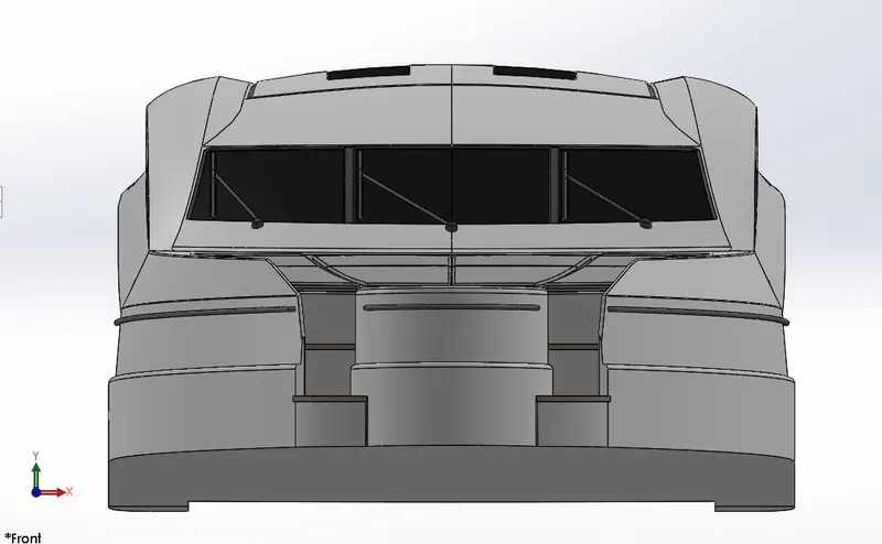
(Front view of the Superstructure)
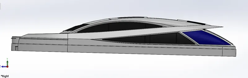
(Right side view of the Superstructure)
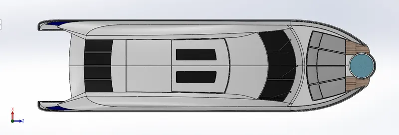
(Top view of the Superstructure)
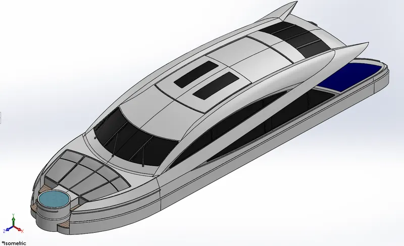
(Isometric view of the Superstructure)
6. Front Seat
- Front seats are placed in the front deck of the yacht and nearer to the jacuzzi bathtub.
- Features used to create front seat in solidworks:
- Surface Sweep
- Surface Extrude
- Surface Trim
- Surface Fill
- Surface Loft
- Surface Knit
- Boss/Base Revolve
- Cut Extrude
- Dome
- Mirror
- Chamfer
- Fillet
- Images:
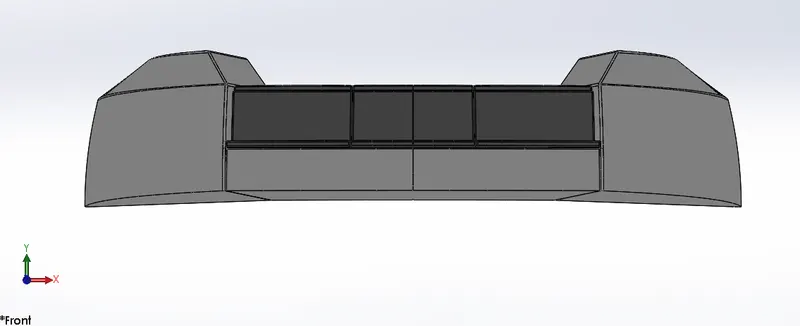
(Front view of the Front seat)
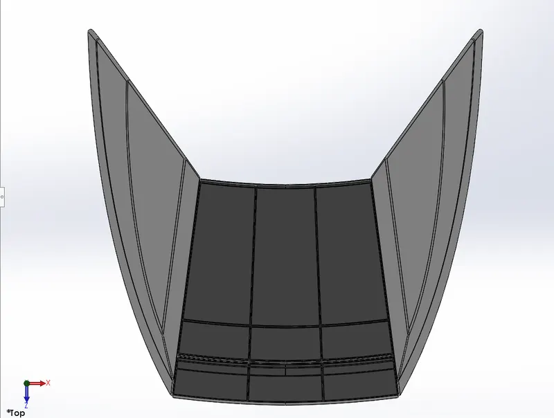
(Top view of the Front seat)
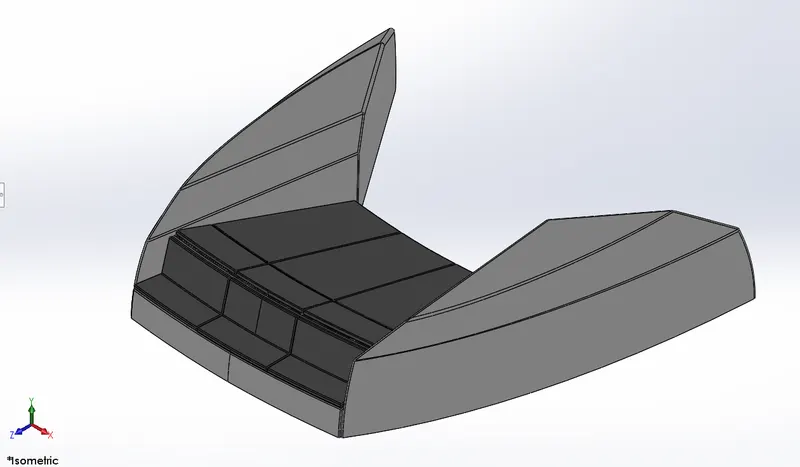
(Isometric view of the Front seat)
7. Middle Seat
- Middle seats are placed in the middle portion of the deck of the yacht. Center table is also there with the middle seat.
- Features used to create middle seat in solidworks:
- Boss/Base Extrude
- Cut Extrude
- Mirror
- Chamfer
- Fillet
- Images:
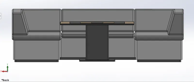
(Front view of the Middle seat)
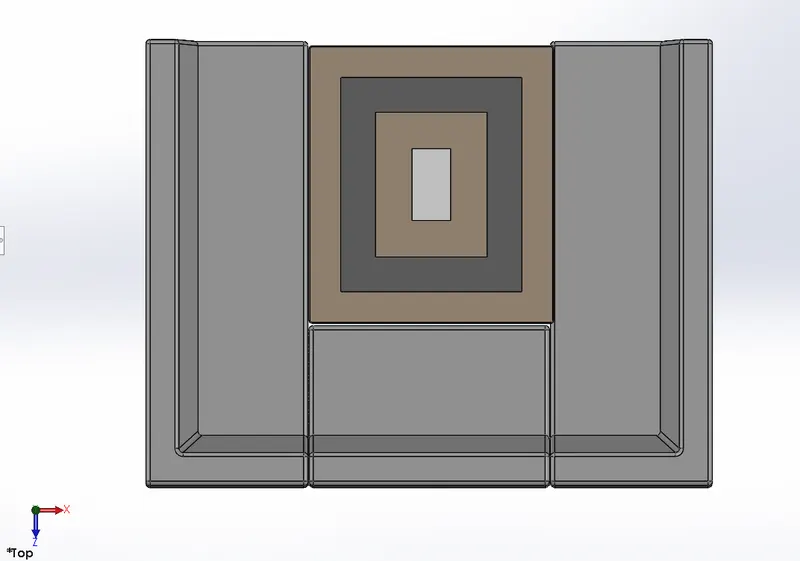
(Top view of the Middle seat)
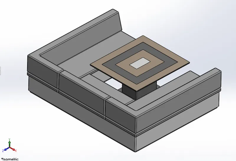
(Isometric view of the Middle seat)
8. Rear Seat
- Rear seats are placed at the back side of the deck of the yacht.
- Features used to create rear seat in solidworks:
- Surface Sweep
- Surface Offset
- Surface Trim
- Surface Ruled
- Surface Knit
- Surface Extend
- Surface Extrude
- Surface Loft
- Boss/Base Extrude
- Boss/Base Sweep
- Boss/Base Revolve
- Cut Extrude
- Mirror
- Chamfer
- Fillet
- Images:
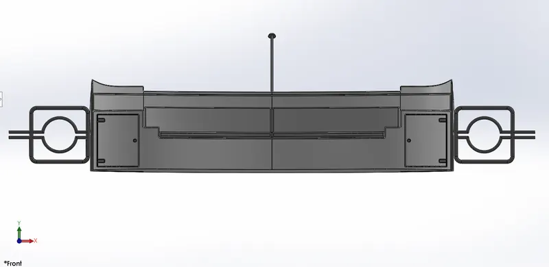
(Fron view of the Rear seat)
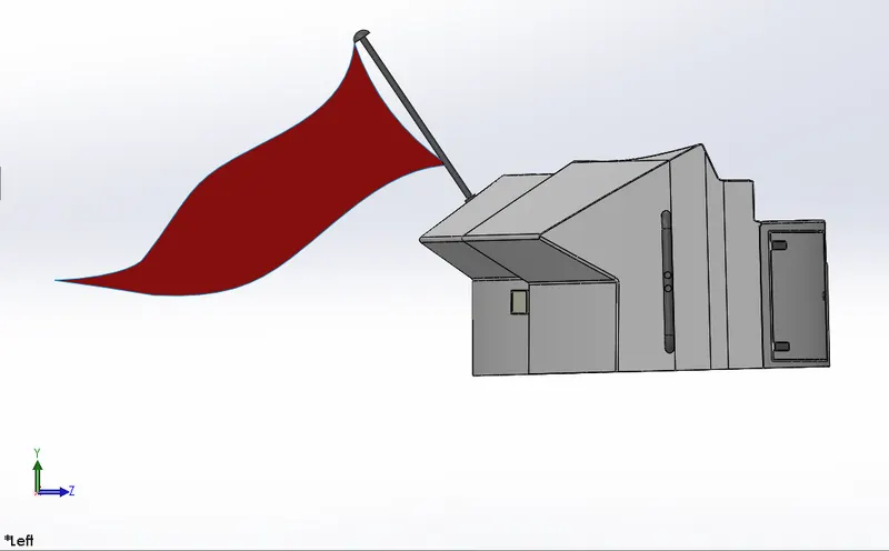
(Left side view of the Rear seat)
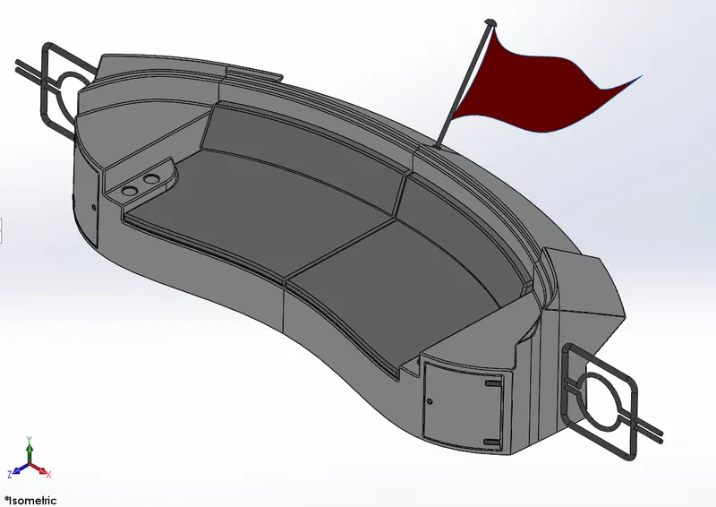
(ISometric view of the Rear seat)
9. Radar Mast
- They are electronic navigation instruments that use a rotating antenna to sweep a narrow beam of microwaves around the water surface surrounding the ship to the horizon, detecting targets by microwaves reflected from them, generating a picture of the ship's surrounding on a display screen.
- Features used to create redar mast in solidworks:
- Boss/Base Extrude
- Boss/Base Revolve
- Boss/Base Sweep
- Reference Geometry - Plane
- Dome
- Shell
- Mirror
- Chamfer
- Fillet
- Images:
(Front view of the Radar Mast)
(Top view of the Radar mast)
(Right side view of the Radar mast)
(Isometric view of the Radar mast)
ASSEMBLY
> Appraoch
- As discuss in the introduction, here Bottom-Up Assembly approach is used. All the parts are made seperately in the part file in solidworks and then bring them all together in assembly file.
- In solidworks, part file is save as .sldprt and assembly file is save as .sldasm.
> Mates
There are mainly 3 types of mates which are used to create assembly in solidworks.
1. Stanadard Mates
- Coincident
- Parallel
- Perpendicular
- Tangent
- Concentric
- Lock
2. Advance Mates
- Profile center
- Symmetric
- Width
- Path mate
- Linear / Linear coupler
3. Mechanical Mates
- Cam
- Slot
- Hinge
- Gear
- Rack pinion
- Screw
- Universal joint
- In this Yacht assembly, these are the following mates used:
- Distance Coincident
- Mid Plane Coincident
- Concentric
- Images:
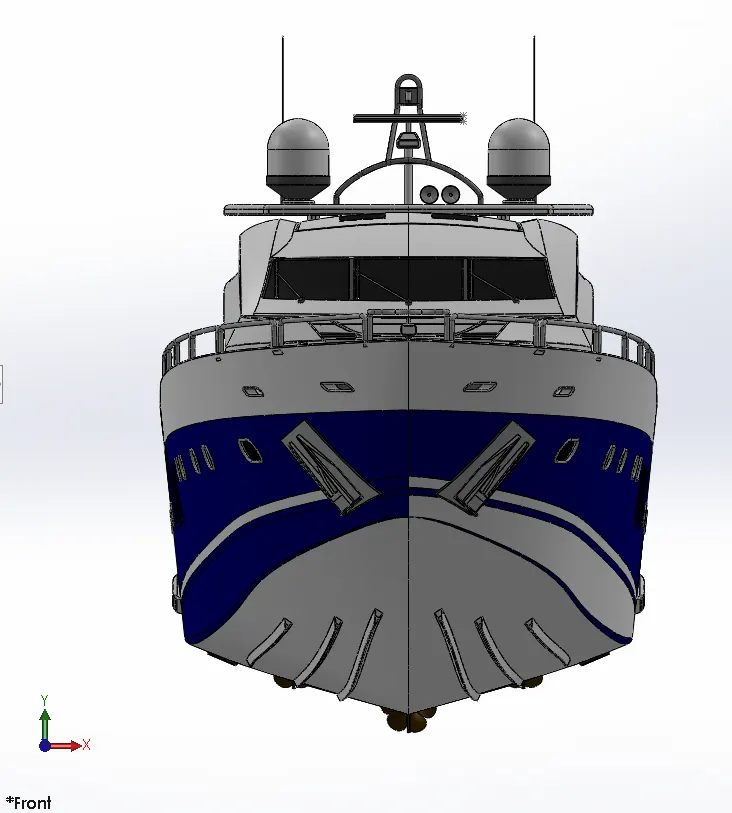
(Front view of the Yacht assembly)

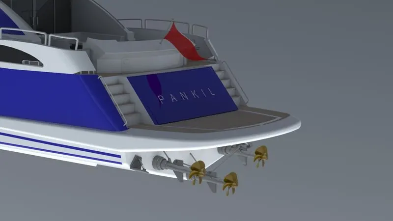
(Back side view of the Yacht assembly)
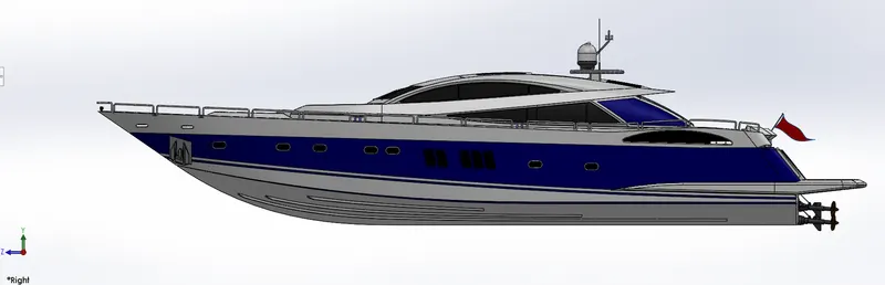
(Right side view of the Yacht assembly)
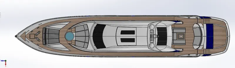
(Top view of the Yacht assembly)
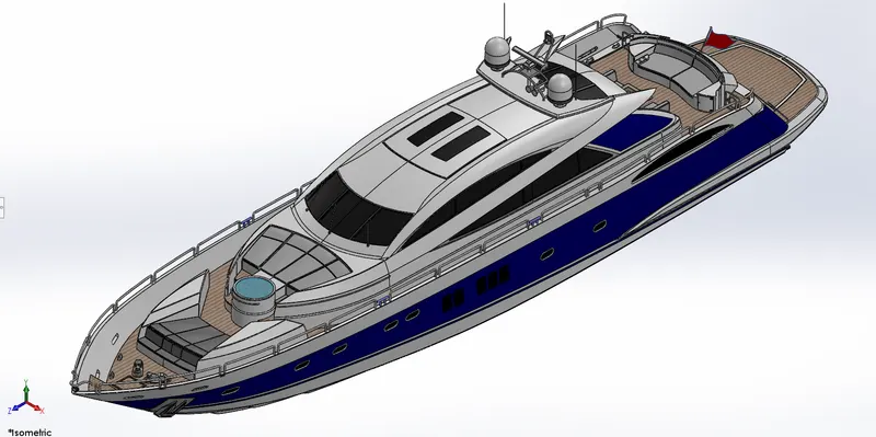
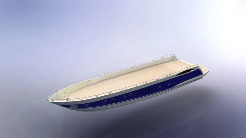
(Isometric view of the Yacht assembly)
RENDERING
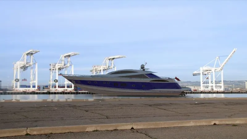
- In this project, photoview 360 is used for rendering.
- To add photoview 360 in solidworks, follow these steps,
Solidworks > Tools > Add-ins > Tick on photoview 360.
- In Photoview 360, there are many options to give final touch to the model for presenting or publishing it.
- In this project, these options are used:
- Edit Decals
- Edit Scene
- Edit Material
- Render Quality
- Add Camera
- Perspective View
- Preview Window
- Final Render
- Images:
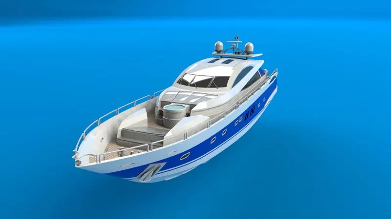
(Image_1)
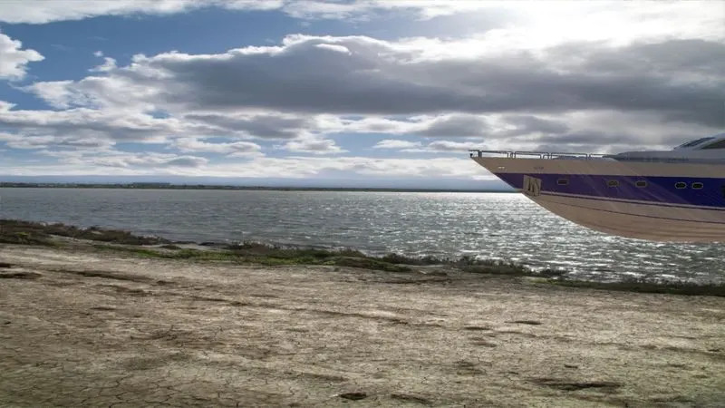
(Image_2)
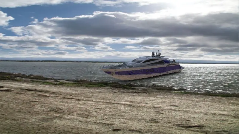
(Image_3)
(Image_4)
(Image_5)
(Image_6)