Photo Realistic Rendering
DESIGNING OF AMERICAN CHOPPER BIKE
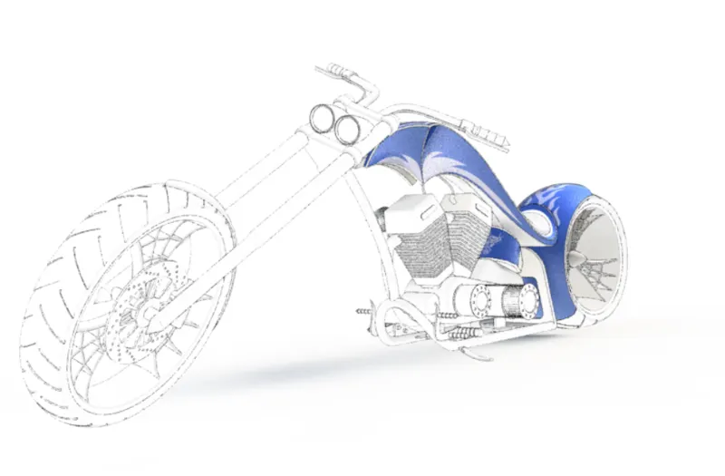
OBJECTIVES
- Detail designing of every part of American Chopper bike.
- To get knowledge of different mates used to assemble the bike.
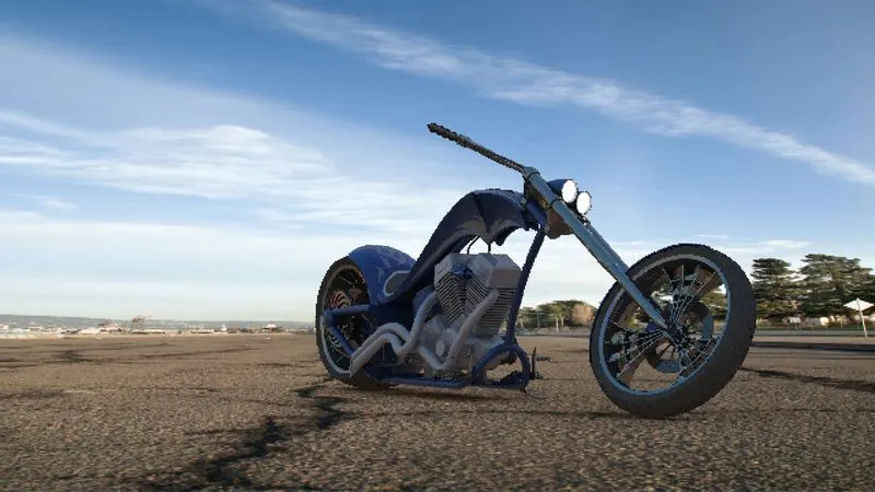
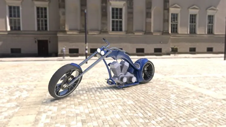
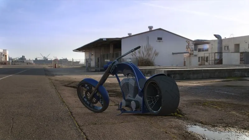
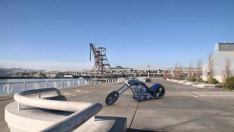
- To get brief knowledge of Photoview 360 rendering tools to do the rendering of American Chopper bike.
INTRODUCTION
In this project we will discuss about the design approach and different tools used in the modeling of American Chopper bike which is one of the most popular bikes in the world.
Part Modeling
- Part modeling is the process of creating a virtual prototype of each part of the model separately and then all the parts assembled together to create the final model.
- The file name extension for part file is .SLDPRT in solidworks software.
Assembly
- Assembly is most often referred to putting components together in an assembly line; it refers to creating a complete product that performs as intended function.
- The file name extension for assembly file is .SLDASM
- For doing assembly, there are mainly 2 approaches.
1. Top Down assembly approach
- In Top Down approach, designing of each component, its shape and sizes and its location can be done in the assembly file.
- The design intent comes from the top, which is assembly, and moves down to the parts.
2. Bottom Up assembly approach
- In Bottom Up approach, firstly designing of each part is done in part file separately and then bring them into the assembly file to make a model.
- In the modeling of American Chopper bike, Bottom Up approach is used.
> VARIOUS PARTS OF THE MODEL
- Transmission belt
- Kickstand
- Front fender
- Rear fender
- Chain
- Oil tank
- Pedal
- Front wheel
- Rear wheel
- Front fork
- Chassis
- Engine
- Gas tank
DESIGN METHODOLOGY
1. TRANSMISSION BELT
Function: Transmission belt is ued to transmit the rotary motion from one shaft to other.
Procedure: Use line and arc command to make a fully defined sketch with the given dimensions and by using offset command offset the whole sketch after that extrude that sketch with the help of boss extrude feature and give fillet to the edges of the belt.
Features:
- Boss Extrude
- Fillet
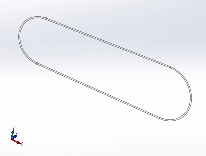
(SKETCH OF THE TRANSMISSION BELT)
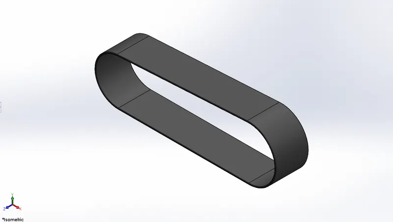
(ISOMETRIC VIEW OF THE TRANSMISSION BELT)
2. KICKSTAND
Function: The Kickstand is usually a piece of metal that flips down from the frame and makes contact with the ground to prevent the bike from falling down.
Features:
- Loft
- Dome
- Extrude cut
- Split
- Boss extrude
- Fillet
Procedure: Make 2 ellipses and a guideline between ellipses and use loft feature to make it solid. Use dome feature to give roundness to the both ends of the kickstand. Use extrude cut feature to cut down one end of the stand from the center and make a pin. Use split feature to make other end of the stand flat as it makes contact with the ground.
Images:
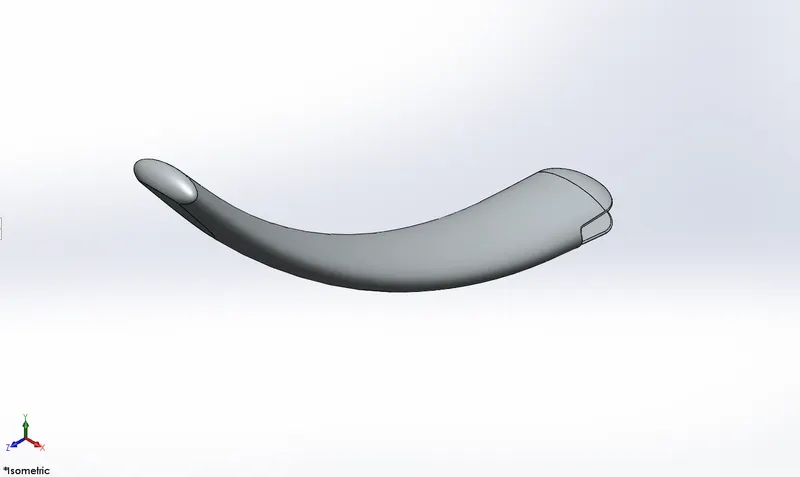
(ISOMETRIC VIEW OF THE KICKSTAND)
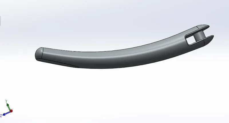
(SIDE VIEW OF THE KICKSTAND)
3. FRONT FENDER
Function: It is used to prevent from sand, rocks, liquids and other road spray from being thrown into the air by rotating wheels, so it is used to protect the driver as well as the engine. As the name states, it will be fitted to the front wheel.
Features:
- Revolve
- Split
- Fillet
Procedure: Make a half round sketch with 3-point arc curve and by using revolve feature revolve that sketch at the certain angle along the axis. Use split feature to give sharp effect at both the end of the fender.
Images:
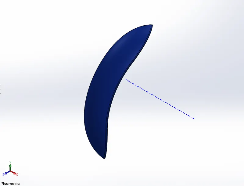
(ISOMETRIC VIEW OF THE FRONT FENDER)
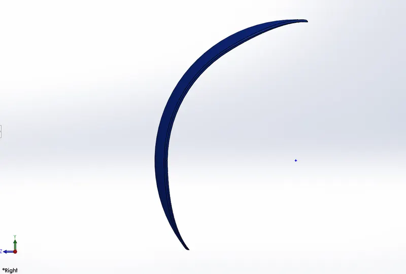
(RIGHT SIDE VIEW OF THE FRONT FENDER)
4. REAR FENDER
Function: Fender is a frame like structure which is laid over a wheel. The rear fender is act same as a front fender, the only difference is that the rear fender will fit to the rear wheel.
Features:
- Revolve
- Split
- Fillet
- Shell
Procedure: Create a 3-point arc curve on the midplane and revolve it at a certain angle along the axis. Use split feature to give curvature at both the ends of the fender. At the end use shell feature to accomodate the rear tyre.
Images:
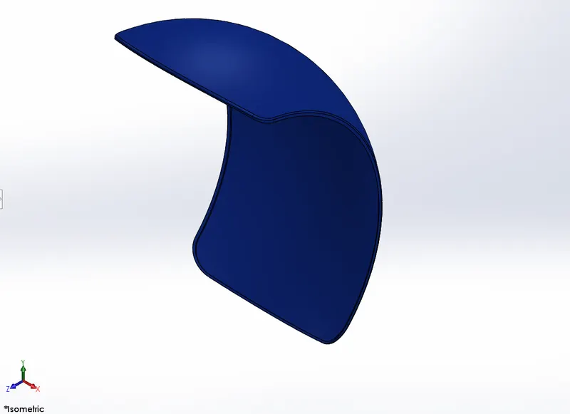
(ISOMETRIC VIEW OF THE REAR FENDER)
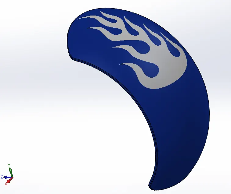
(SIDE VIEW OF THE REAR FENDER)
5. CHAIN
Function: In bike, chain is a part of the drive train which transmits the power from the engine to the rear wheel.
Features:
- Boss extrude
- Block
- Mirror
- Curve driven pattern
- Fillet
Procedure: Make a construction line as per given dimension with help of the circle, 3-point curve and line. Then make a sketch of pins and 2 chain plates on the construction line and make block of these sketches. With the help of curve driven pattern feature generate a pattern of these sketches on the construction line. Use coincident and concentric mates to combined pins and chain plates with each other. Extrude pins and chain plates and mirror chain plates at the other end of the pin.
Images:
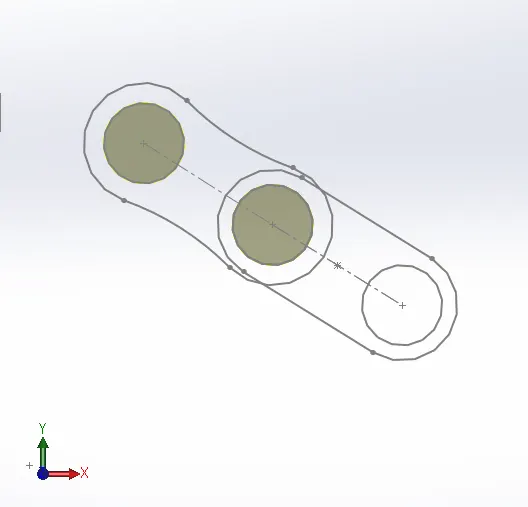
(SKETCH OF THE CHAIN PLATES AND PINS)
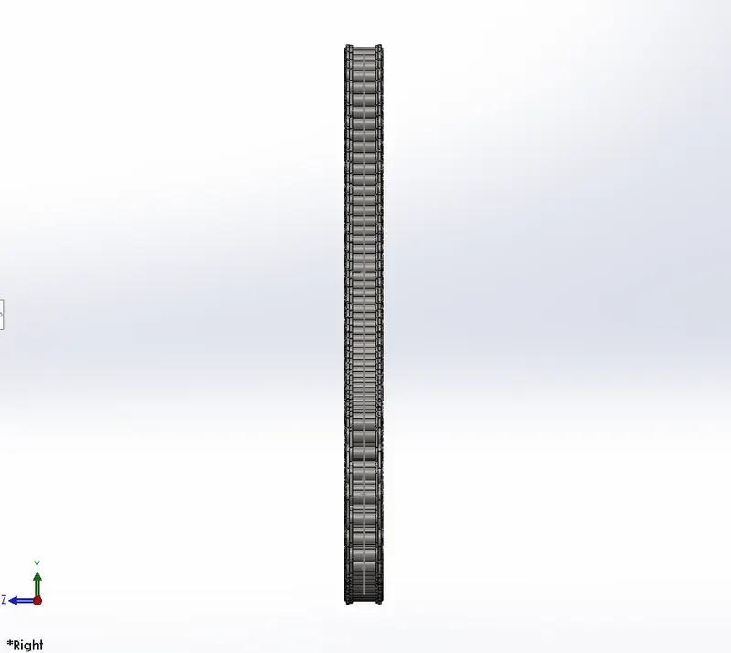
(RIGHT SIDE VIEW OF THE CHAIN)
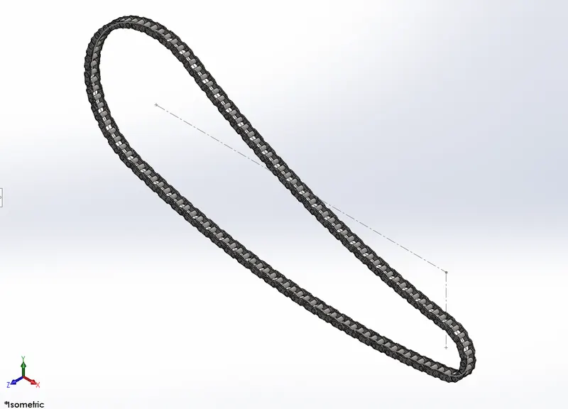
(ISOMETRIC VIEW OF THE CHAIN)
6. OIL TANK
Function: The oil tank is used to store the fuel, which helps in cooling and lubricating the engine.
Features:
- Boss extrude
- Combine
- Fillet
- Shell
Procedure: Create 2 sketches, one is the base of the oil tank and the other is the side view of the oil tank. Extrude these sketches. Use combine feature to make integrated part from 2 extruded soli bodies which is intersect with each other. Give fillet to all the edges. Use shell feature to make oil tank hollow.
Images:
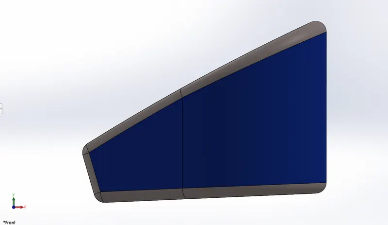
(FRONT VIEW OF THE OIL TANK)
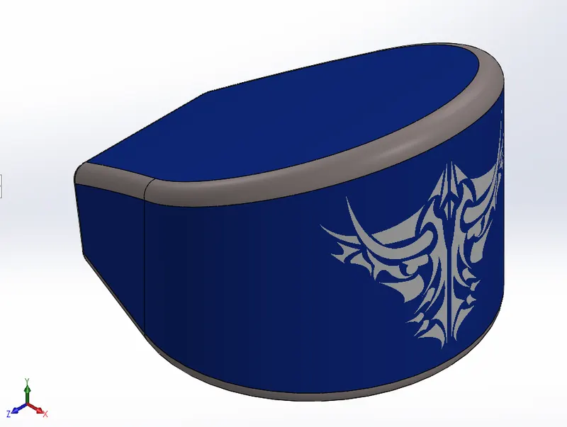
(SIDE VIEW OF THE OIL TANK)
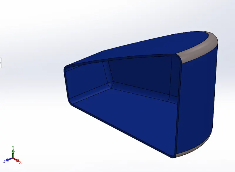
(SECTIONAL VIEW OF THE OIL TANK)
7. PEDAL
Function: The purpose of the pedal for the rider is to rest their feet on it and maintain balance to ride a bike.
Features:
- Boss extrude
- Boss revolve
- Dome
- Linear pattern
- Chamfer
- Fillet
Procedure: Make a sketch of a lever with the given dimensions. Extrude it and make 2 pins on it which is used to fix the pedal on the mian frame. Now make a line on the other side of the lever which is perpendicular to the lever and revolve it and make 2 more circles on the lever and extrude them. Now make a ring on each rod and use linear pattern feature to make grip on the rods. Use dome and chamfer at the end of the rods to give roundness and sharpness effect.
Images:
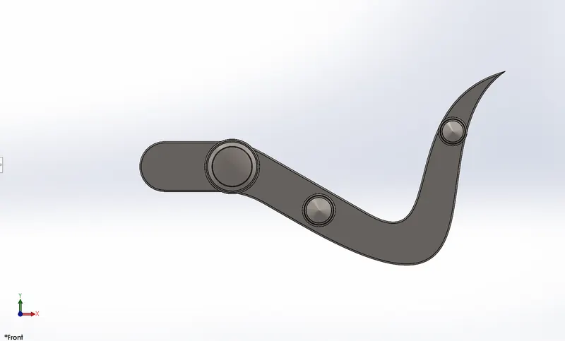
(FRONT VIEW OF THE PEDAL)
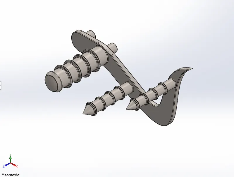
(ISOMETRIC VIEW OF THE PEDAL)
8. FRONT WHEEL
Function: The wheel is mainly used for transportation, it allows heavy objects to be moved easily. The front wheel is used to navigate the bike.
Features:
- Boos revolve
- Boss extrude
- Extruded cut
- Revolved cut
- Circular pattern
- Combine
- Fillet
Procedure: Make a sketch on the right plane and revolve it to make a rim of the wheel. On the front plane make a sketch and use boss extrude, extruded cut, revolved cut and circular pattern to make spokes of the wheel. Again, make a sketch on the front plane and extrude it to make a rotor for the brake. Use extruded cut and circular pattern to make holes in the rotor. Now make a sketch of the caliper and extrude it to the both sides of the rotor. Now again make a sketch on the right plane and revolve it to make a tire. Use extruded cut and circular pattern to make threads on the tire.
Images:
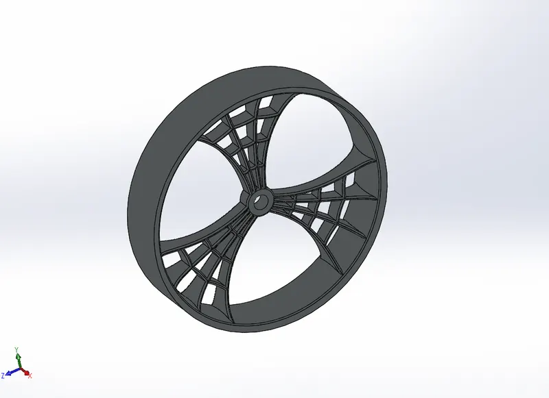
(RIM OF THE FRONT WHEEL)
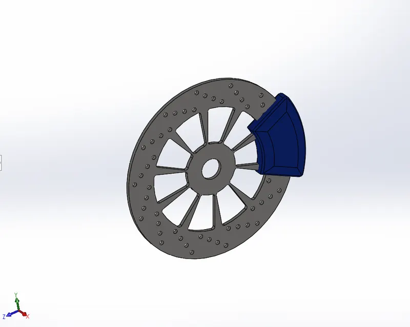
(ROTOR AND CALIPER OF THE FRONT WHEEL)
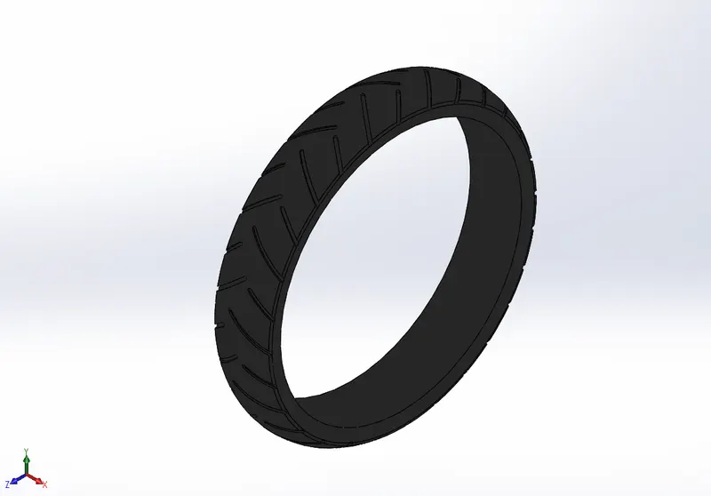
(TIRE OF THE FRONT WHEEL)
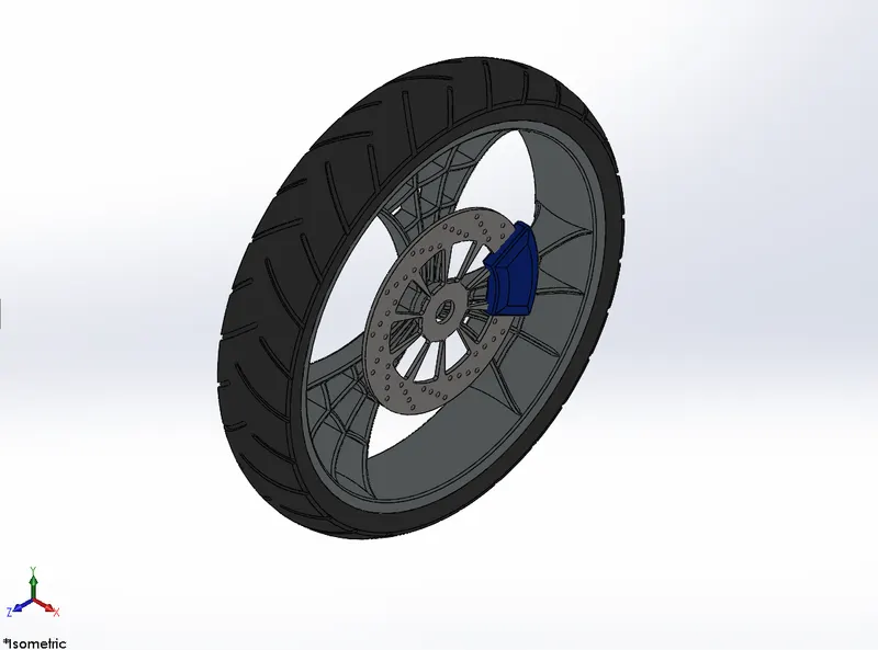
(ISOMETRIC VIEW OF THE FRONT WHEEL)
9. REAR WHEEL
Function: The main function od the rear wheel is to give motion to the bike. With the help of the drive train, power is transferred to the rear wheel from the engine and it rotates the rear wheel.
Features:
- Boss revolve
- Boss extrude
- Extruded cut
- Revolved cut
- Circular pattern
- Combine
- Chamfer
- Fillet
Procedure: Same as the front wheel, first make a sketch and revolve it to make a rim of the wheel. Then, by using boss extrude, extruded cut, revolved cut and circular pattern make spokes of the wheel. Make rotor and caliper using boss extrude, extruded cut, and circular pattern. Now, near the rotor make another sketch and make sprocket by using boss extrude, extruded cut and circular pattern. Sprocket is used to hold the chain which is transmitting the power from the engine. Again, to make a tire make a sketch and revolve it and make threads on it use extruded cut and circular pattern.
Images:
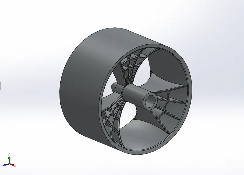
(RIM OF THE REAR WHEEL)
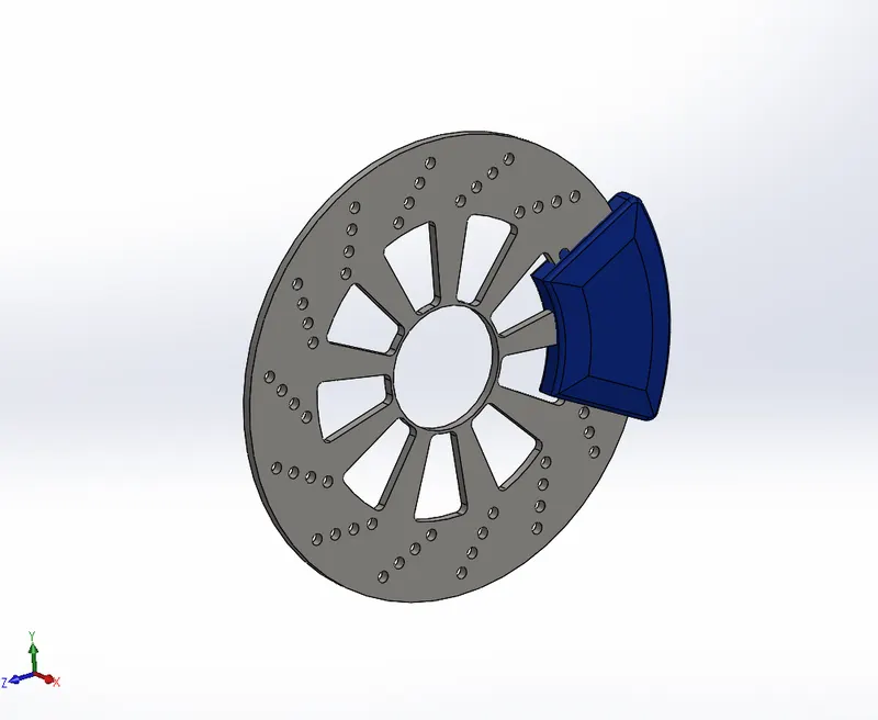
(ROTOR AND CALIPER OF THE REAR WHEEL)
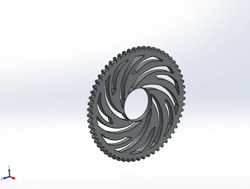
(SPROCKET OF THE REAR WHEEL)
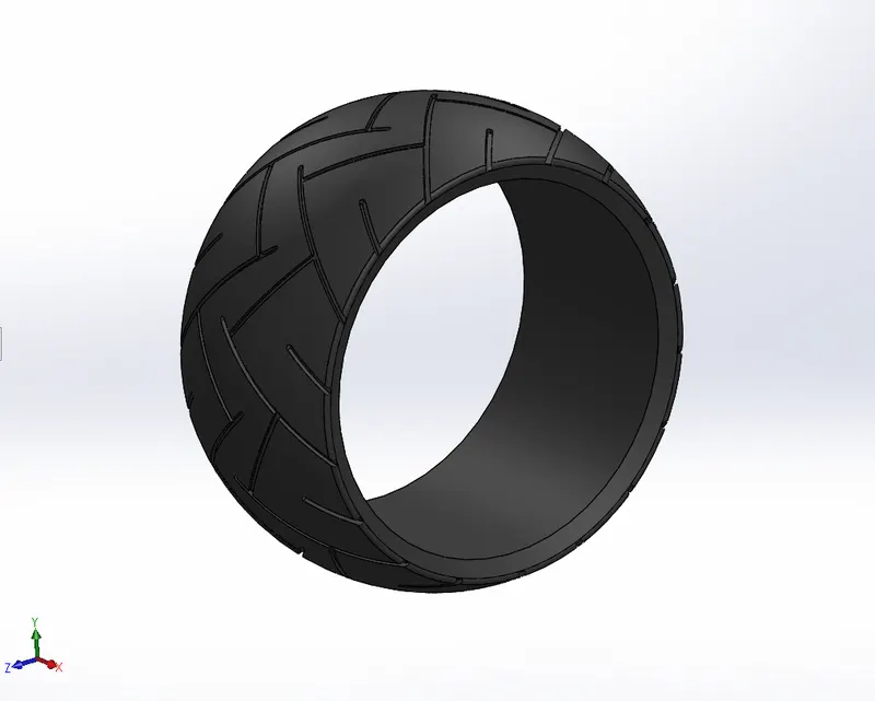
(TIRE OF THE REAR WHEEL)
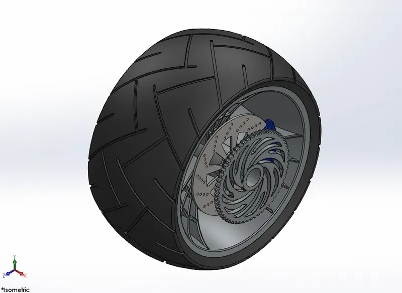
(ISOMETRIC VIEW OF THE REAR WHEEL)
10. FRONT FORK
Function: Fork is the part of the bike that holds the front wheel. The fork is the suspension at the front of the bike which is connected between the front wheel and the handlebar allowing the rider to steer the bike.
Features:
- Boss revolve
- Boss extrude
- Linear pattern
- Extruded cut
- Dome
- Revolved cut
- Projected curve
- Sweep
- Mirror
- Combine
- Fillet
Procedure: First, make a sketch for the fork tube and revolve it. Make a sketch for the steering base and extrude it. Steering base is used to connect the fork tubes with the handle and also use to fix the headlight. Make headlight between 2 steering base plates using revove and extruded cut. Use dome and revolved cut features to give headlight's glass type effect in the headlight. Now use the projected curve feature to create a path for the handle bar. Create a circle at one end of the path and use sweep feature to make a handle bar. Likewise, create the brake and brake wire. Now fork tube, haedlight, handle bar, brake and brake wire all the necessary parts are done. Now mirror all these parts and combine them to make one single unit.
Images:
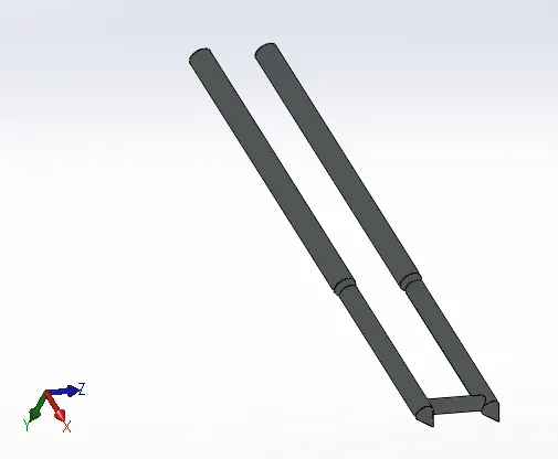
(FORK TUBE)
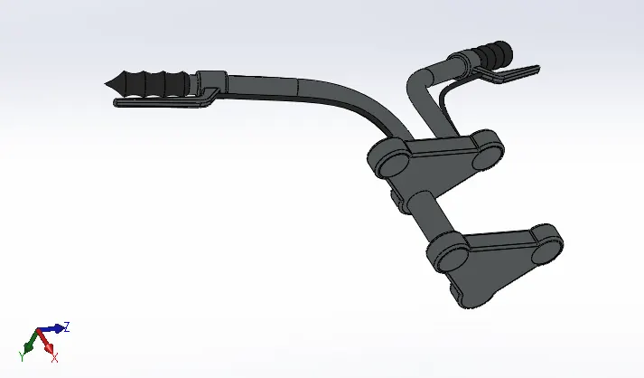
(HANDLE BAR)
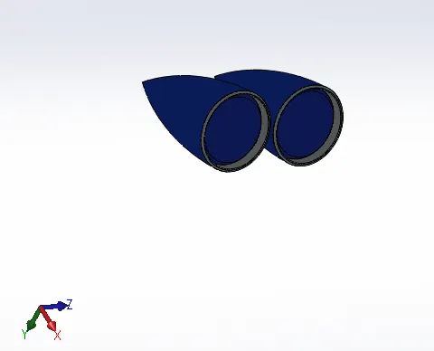
(HEADLIGHT)
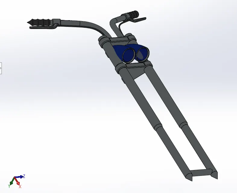
(CAMERA ANGLE VIEW OF THE FRONT FORK)
11. CHASSIS
Function: All the components of the bike, like wheels, fuel tank, seats, handlebar, engine, etc. are attached to this structure which lends a bike its strength and ability to handle well.
Features:
- Projected curve
- Sweep
- Mirror
- Boss extrude
- Extruded cut
- Dome
- Split
- Combine
- Chamfer
- Fillet
Procedure: Import the American chopper bike's blueprint. Use image sketch feature and make sketch with reference to the image with the help of spline, line and projected curve. Use sweep, extrude, cur extrude and mirror features to make the frame.
Images:
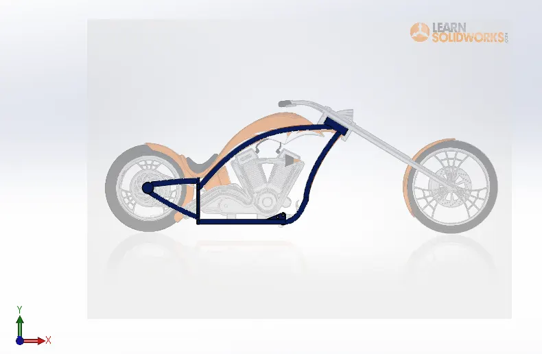
(BLUEPRINT OF THE MODEL WITH CHASSIS)
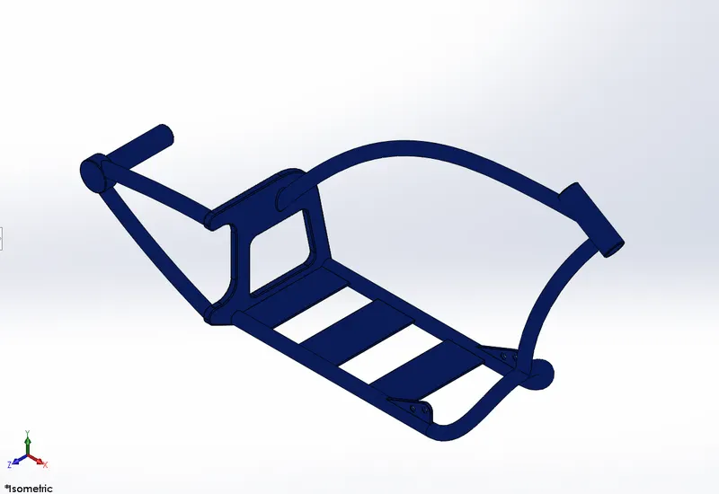
(ISOMETRIC VIEW OF THE CHASSIS)
12. ENGINE
Function: Motorcycle engine is that powers motorcycle. Engine consists of piston, crankshaft, cylinder block, etc. As the piston moves up and down, it turns a crankshaft, which transforms the energy from the pistons into rotary motion.
Features:
- Boss extrude
- Boss revolve
- Extruded cut
- Dome
- Circular pattern
- Linear pattern
- Mirror
- Sweep
- Split
- Chamfer
- Fillet
Procedure: Import blueprint of the American chopper model, using image sketch feature and make sketches with reference to the image on different plane and by using boss extrude, boss revolve, pattern and sweep features make engine of the bike.
Images:
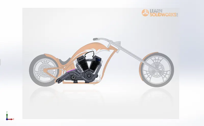
(BLUEPRINT OF THE MODEL WITH ENGINE)
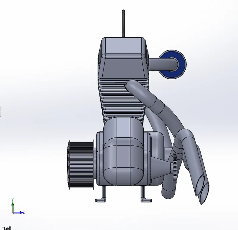
(LEFT SIDE VIEW OF THE ENGINE)
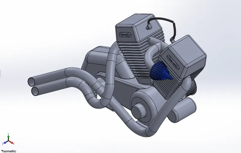
(ISOMETRIC VIEW OF THE ENGINE)
13. GAS TANK
Function: A gas tank is safe container for flammable fluids. It is a part of an engine system in which the fuel is stored and released into an engine.
Features:
- Surface sweep
- Surface trim
- Surface loft
- Surface extrude
- Mirror
- Swept cut
- Shell
- Fillet
Procedure: Again import blueprint of the American chopper bike, use image sketch feature and make sketches on the image. Use different surface modeling features like surface sweep, surface loft, surface extrude to make the gas tank.
Images:
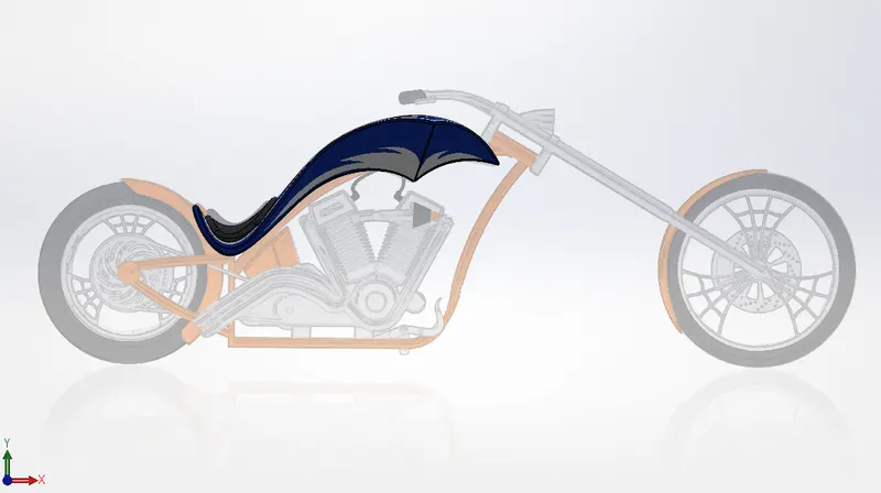
(BLUEPRINT OF THE MODEL WITH THE GAS TANK)
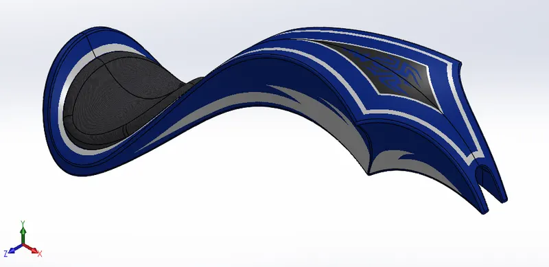
(ISOMETRIC VIEW OF THE GAS TANK)
FEATURES DESCRIPTION
- BOSS EXTRUDE
- It requires a fully defined sketch to extrude.
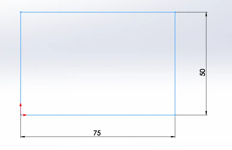
(FULLY DEFINED SKETCH)
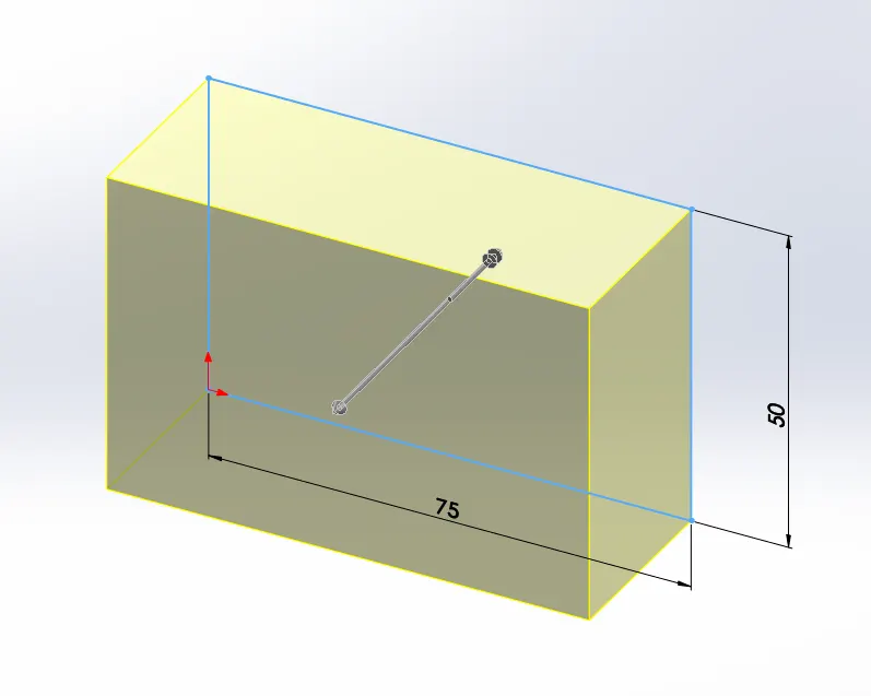
(AFTER APPLYING EXTRUDE)
- EXTRUDED CUT
- It requires an extruded part and fully defined sketch on one of its face.
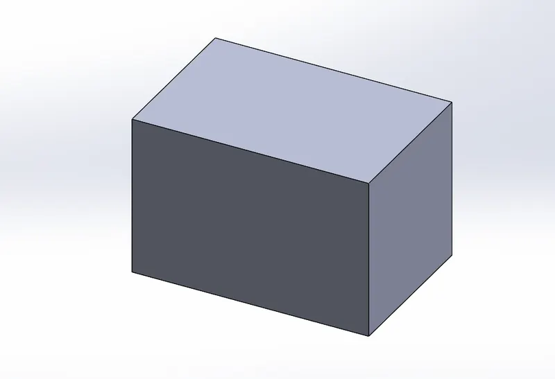
(EXTRUDED PART)
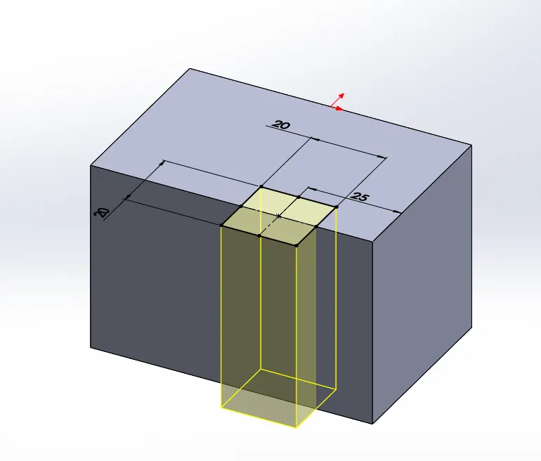
(FULLY DEFINED SKETCH ON ONE SURFACE)
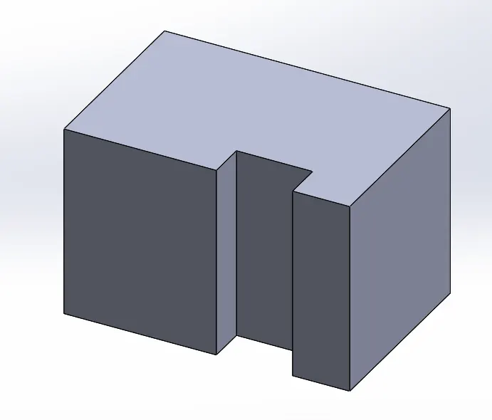
(AFTER APPLYING EXTRUDED CUT)
- BOSS REVOLVE
- It requires a fully defined sketch and one aixs fo reference.
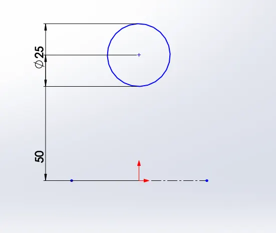
(FULLY DEFINED SKETCH WITH REFERENCE AXIS)
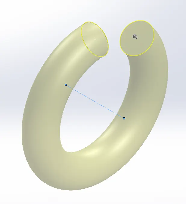
(AFTER APPYLING BOSS REVOLVE)
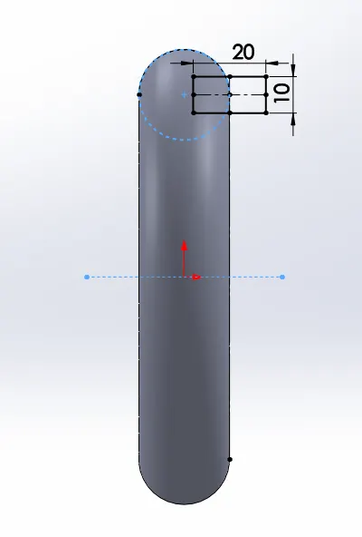
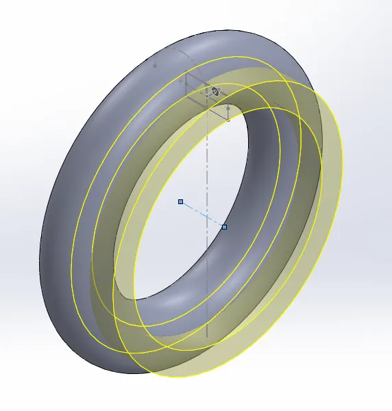
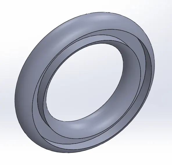
- REVOLVED CUT
- It requires one solid part and a fully defined sketch with reference axis.
(SOLID PART AND FULLY DEFINED SKETCH)
(REVOLVING ALONG THE REFERENCE AXIS)
(AFTER APPLYING REVOLVED CUT)
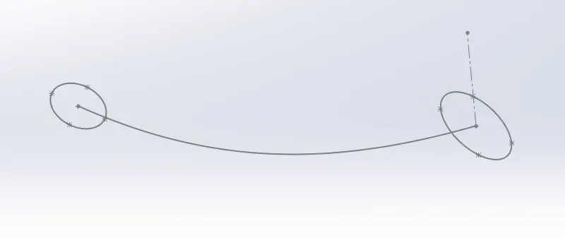
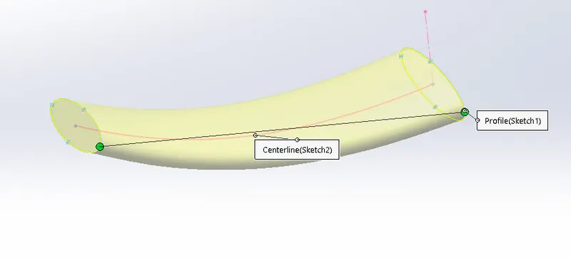
- LOFT
- It requires minimum of 2 fully defined sketches and 1 guide line between these sketches.
(SKETCHES WITH A REFERENCE LINE)
(AFTER APPLYING LOFT)
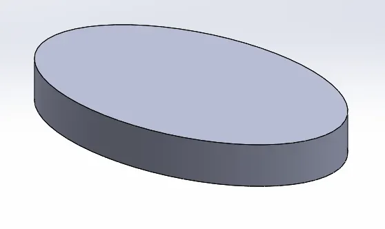
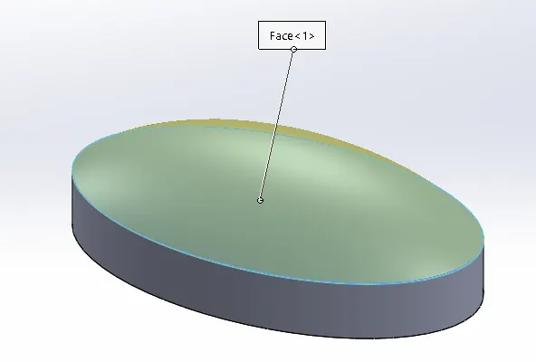
- DOME
- It requires a solid surface to lift it up from its center.
(SOLID SURFACE)
(AFTER APPLYING DOME)
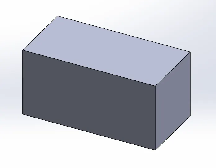
- SHELL
- It requires any solid body.
(SOLID BODY)
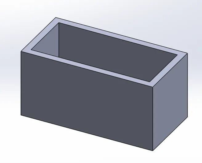
(AFTER APPLYING SHELL)
- MIRROR
- It requires a fully defined sketch or a solid part and a plane, a surface or an axis.
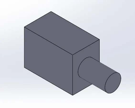
(SOLID PART)
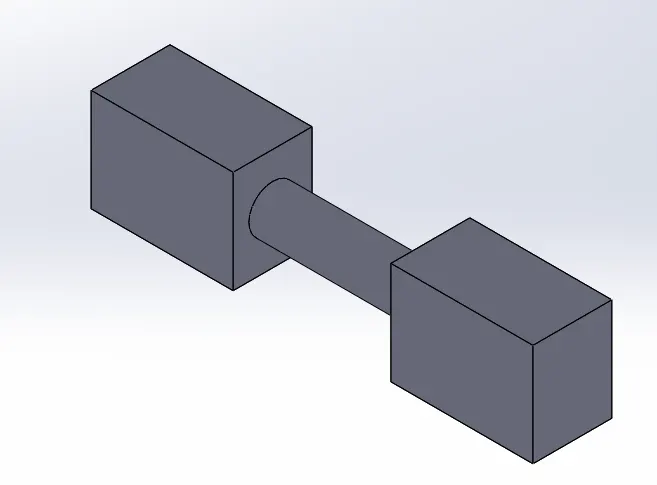
(AFTER APPLYING MIRROR)
- PATTERN
- It requires a fully defined sketch or a solid part and a reference line.
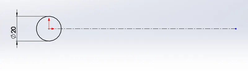
(FULLY DEFINED SKETCH WITH REFERENCE LINE)
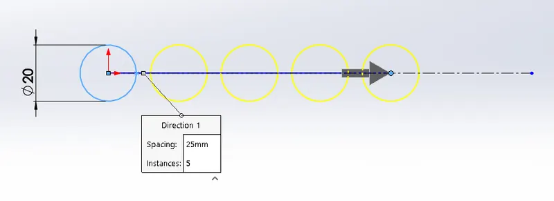
(AFTER APPLYING PATTERN)
- SWEPT BOSS
-It requires a fully defined sketch and one reference line.
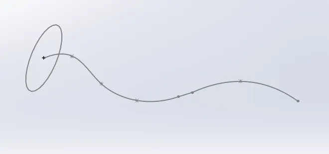
(FULLY DEFINED SKETCH WITH REFERENCE LINE)
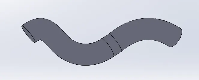
(AFTER APPLYING SWEPT BOSS)
- CHAMFER / FILLET
- It applies where the two edges of any solid part or a sketch are connects or intersects each other.
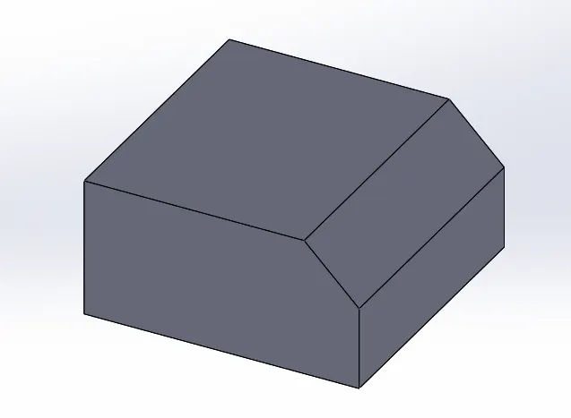
(CHAMFER ON THE EDGE OF THE SOLID PART)
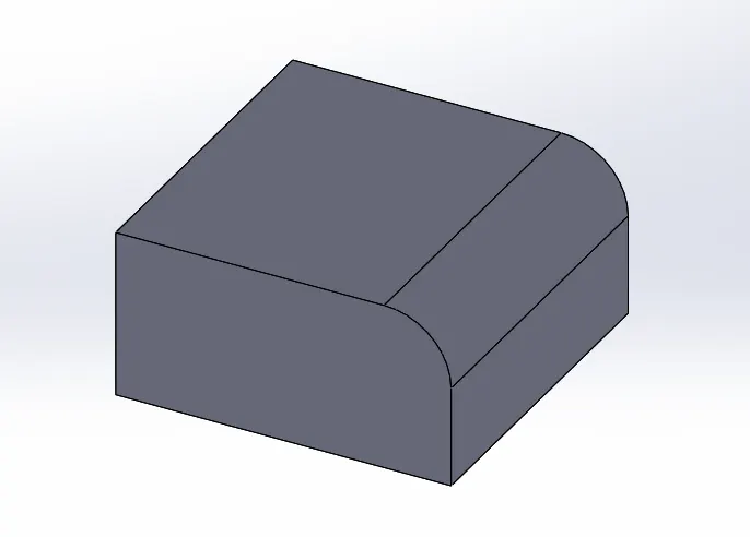
(FILLET ON THE EDGE OF THE SOLID PART)
ASSEMBLY OF AMERICAN CHOPPER BIKE
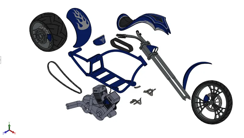
( EXPLODED VIEW OF THE MODEL)
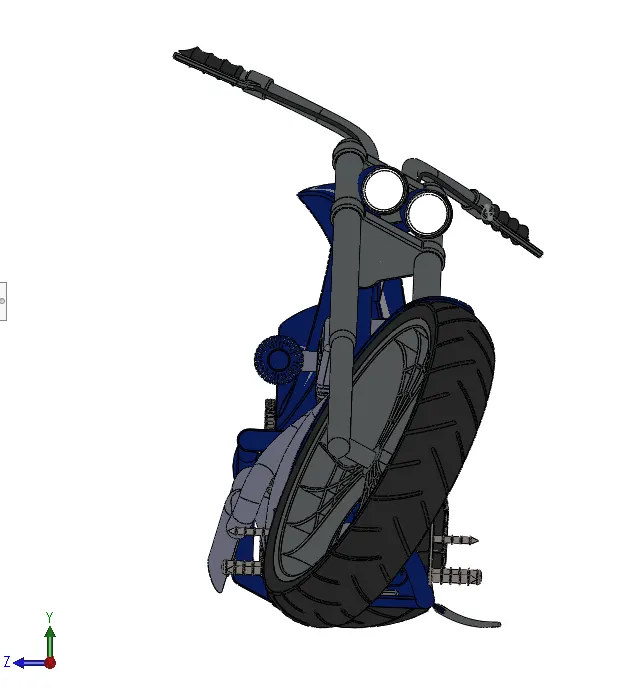
(FRONT SIDE OF THE MODEL)
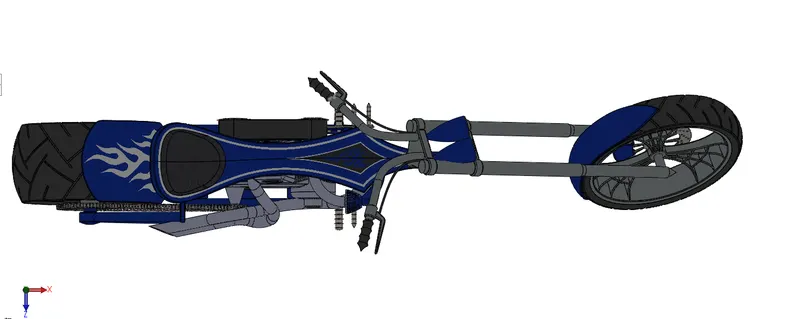
(TOP SIDE OF THE MODEL)
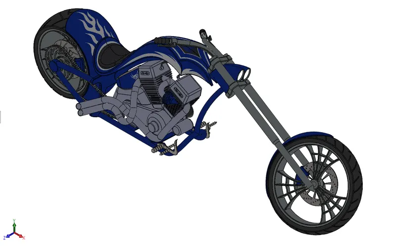
(ISOMETRIC VIEW OF THE MODEL)
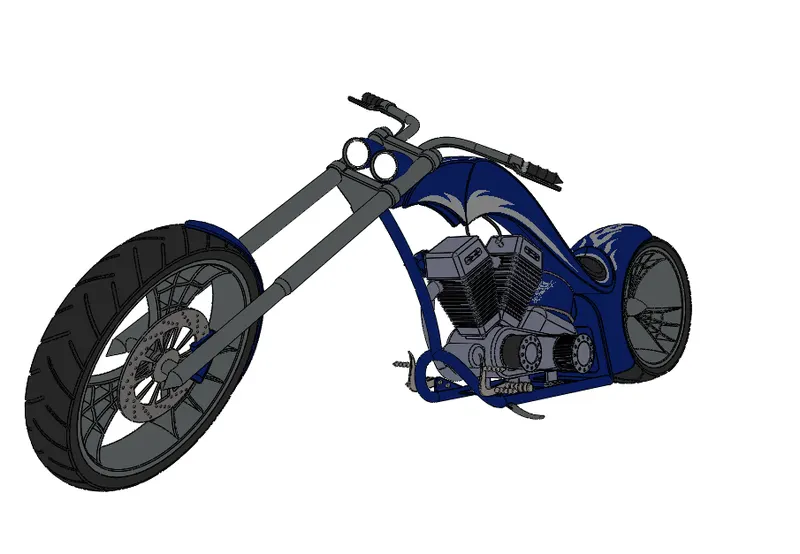
(CAMERA VIEW OF THE MODEL)
RENDERING
Rendering features:
- Environment setup
- Colors and material
- Scene composition and setup
- Light setup
Rendering Images:
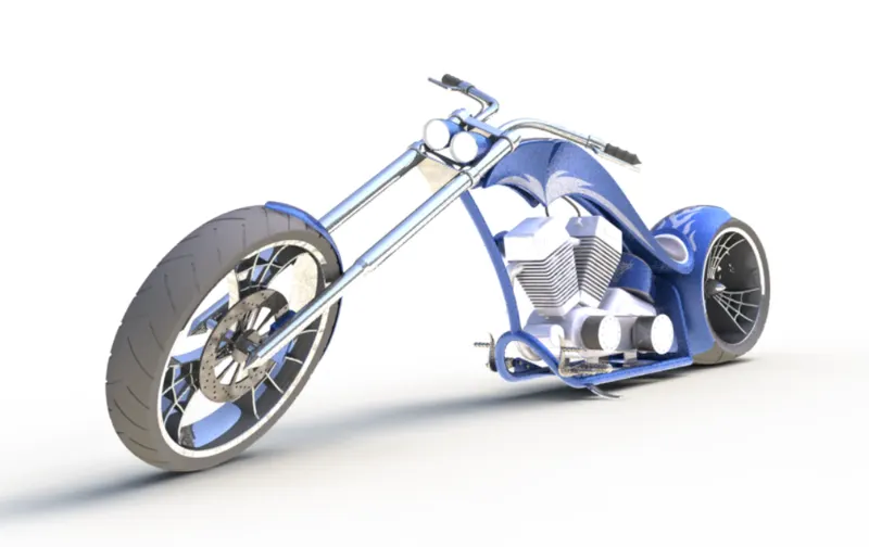
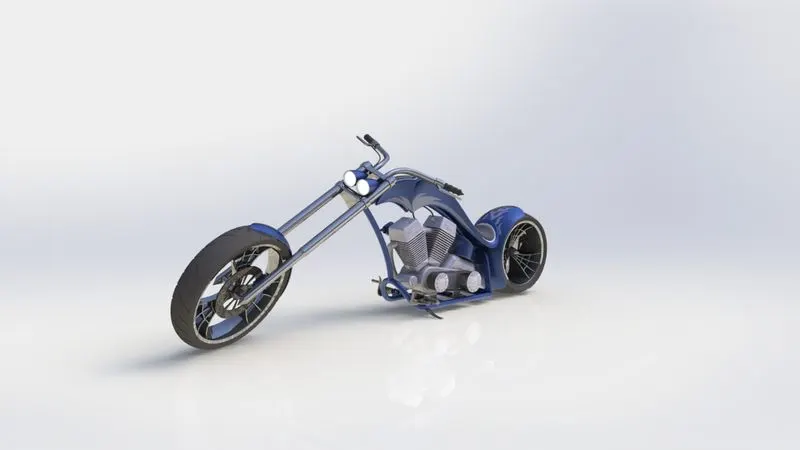
CONCLUSION
In this American Chopper Bike project, learned different features and tools. Also learned about the assembly approach and advance mates which help to locate all the parts in the assembly environment. Learned about the PhotoView 360 for final rendering.