Radar Mast & Final Assembly of Yacht
AIM
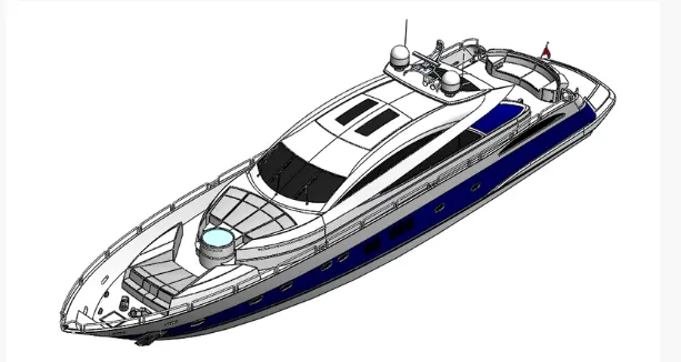
The Project Report is about the Designing, Modelling, and Photo Rendering of Yacht using Solidworks 2021 and Solidworks Visualize 2021.
OBJECTIVE
To Design and model each component required to make assembly of a Yacht in Solidworks and finally make a Photorealistic Rendering of the complete assembly of Yacht. And to get a better insight of the features and tools which are used for modeling of the part and to know how exactly they work and also to get familiar with the user interface of the Solidworks
Yatch Modelling
A yacht is a sailing or power vessel used for pleasure, cruising, or racing. There is no standard definition, so the term applies to such vessels that have a cabin with amenities that accommodate overnight use. To be termed a yacht, as opposed to a boat, such a pleasure vessel is likely to be at least 33 feet (10 m) in length and may have been judged to have good aesthetic qualities .The Commercial Yacht Code classifies yachts 79 ft (24 m) and over as large. Such yachts typically require a hired crew and have higher construction standards. Further classifications for large yachts are: commercial—carrying no more than 12 passengers, private—solely for the pleasure of the owner and guests, the country under which it is registered
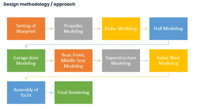
Flow Diagram for modelling Yatch
Tools used in modelling Yatch Modelling
- Revolve- the Revolve feature creates geometry from a sketch. However, the Revolve requires one more ingredient, the Axis of Rotation. Once you have a sketch, the next element is the center line, axis or internal line, of the sketch
- Loft-A loft creates a feature by making transitions between two or more sketch profiles. When you create a loft, the sketch profiles must reside on different planes (or planar faces).
- Circular pattern-A circular pattern is an radial arrayof objects around a. Center point in a sketch. Axis in a part or assembly.
- Fillet-Fillet/Round creates a rounded internal or external face on the part
- Cut extrude-This is a handy feature to aid in material removal of a 3D model using 2D sketches.
- Offset Enities-Copy a sketch entity to a specified distance from the original entity. Must have a sketch entity already drawn and selected to use this tool. Select the offset distance in the property manager by left clicking in the offset distance text box ( ) and specifying the value
- Boss Base Extrude- Extrude tool is used to extend a sketched profile in one or two directions as either a thin feature or a solid feature. An extrude operation can either add material to a part (in a base or boss) or remove material.
- Mirror- Create a reflected copy of a desired entity about a centerline or axis. Make sure the entities to mirror box is highlighted in the property manager. Select the desired entities to mirror, or replicate by left clicking on each. Select the mirror about box in the property manager by left clicking in the text box. Then left click the centerline/axis.
- Split line-It divides a selected face into multiple separate faces. You can split curves on multiple bodies with one command.
- Curve-You can project a sketched curve onto a model face to create a 3D curve. You can also create a 3D curve that represents the intersection of two extruded surfaces generated by creating sketches on two intersecting planes. You can create a helix or spiral curve in a part.
- Surface trim-Trim sketch entities to the desired shape. To trim a section left click on the desired sketch entity to cut away. Several trim options include power trim, corner, trim away inside, trim away outside, and trim to closest.
- Surface fill-The Filled Surface feature constructs a surface patch with any number of sides, within a boundary defined by existing model edges, sketches, or curves, including composite curves. You can use this feature to construct a surface to fill a gap in a model
- Surface knit-Use the Knit Surface tool to combine two or more faces and surfaces into one.
- Shell-The shell tool hollows out a part, leaves open the faces you select, and creates thin-walled features on the remaining faces. If you do not select any face on the model, you can shell a solid part, creating a closed, hollow model. You can also shell a model using multiple thicknesses.
- Chamfer-The chamfer tool creates a beveled feature on selected edges, faces, or a vertex.
- Sweep-SWEEP is the one feature in Solidworks that helps sweep a closed profile along a closed or open path.
- Dome-The software calculates the distance using the radius of the arc as a basis for the dome. It creates a dome that is tangent to the adjacent cylindrical or conical face
- Helical spring-A helix is a twisted, spiral shape, like a corkscrew. In math, a helix is defined as "a curve in three-dimensional space." If you have ever seen a spiral staircase, you can envision the shape of a helix.
- Linear Pattern- Pattern a sketch entity either horizontally, vertically, or angled. Under the property manager the user can specify the distance between the original sketch entity and the patterned copy, the number of instances, and an angle the pattern will appear. Sketch entities can be skipped by selecting the drop down arrow in instances to skip, selecting the text box, and then left clicking the patterned entities to skip. The circular pattern tool can be found under the drop down arrow. It performs similarly to the linear sketch pattern except that it requires the user to specify a point to revolve about and a radius.
- Line-Sketch a horizontal, vertical, or angled line. Double click to end the line. Also start a line by holding the left mouse button and end the line by releasing the button. The centerline tool can be accessed through the drop down arrow and performs the same way.
- Smart dimension-Creates a dimension for a selected sketch entity.
- Corner Rectangle-Sketch a rectangle or square. Each rectangle tool shows the user inputs in the tool by denoting the mouse “clicking” points as small red circles. Additional tools such as parallelogram, center rectangle, 3 point corner rectangle, and 3 point center rectangle can be found under the drop down arrow. These function the same as the corner rectangle tool.
- Tangent Arc- An incomplete circle defined by its tangency to the sketch entity. Specify the tangent arc by left clicking a sketch endpoint and then left click to specify the endpoint of the arc. Additional tools such as center point arc and 3 point arc can be found under the drop down arrow. They function similarly to the tangent arc by asking the user to input the defining arc points.
- Sketch Fillet- A tangent arc inbetween two sketch entities. Specify the radius by left clicking in the radius text box in the property manager.
- Spline-A two or three dimensional curve defined by a set of control points. Points within a spline can be added or deleted by left clicking on the spline point and saying delete, or add spline point.
- Plane- Inserts a plane in a 3D sketch. Must be in the 3D sketching tool to use it. Useful as construction geometry to help define the sketch entity. Define the plane through either the sketch or the models reference planes. The property manager will appear on the left hand side to aid in defining the plane.
- Convert Enities-Project a sketch entity, face, edge, curve, or contour onto the open sketch plane. To convert entities left click on the desired sketch, face, edge, contour, or curve and then left click on convert entities. A new sketch will be created on the plane fully defined using the geometry of the selected entity.
- Combine Tool-In a multibody part, you can combine multiple solid bodies to create a single-bodied part or another multibody part. You can add or subtract bodies, or keep material that is common to the selected bodies.
PROPELLERS
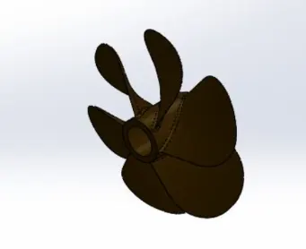
A propeller is a rotating fan-like structure that is used to propel the ship by using the power generated and transmitted by the main engine of the ship.The transmitted power is converted from rotational motion to generate a thrust which imparts momentum to the water, resulting in a force that acts on the ship and pushes it forward.A ship propels on the basis of Bernoulli’s principle and Newton’s third law. A pressure difference is created on the forward and aft side of the blade and water is accelerated behind the blades.
Command used here is:-
- Revolve
- Loft
- Circular pattern
- Fillet
- Cut extrude
RADAR
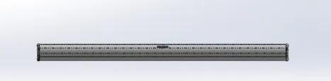
Marine radars are the best collision avoidance system ever developed for the recreational boater. Radar systems let you “see” through darkness, fog and stormy weather conditions. Radar (Radio Detection and Ranging) is a detection system that uses radio waves to determine the distance (range), angle, or velocity of objects. It can be used to detect aircraft, ships, spacecraft, guided missiles, motor vehicles, weather formations, and terrain.
Command Used:-
- Boss Base Extrude
- Fillet
- Cut extrude
- Mirror
- Split line
Blue Print
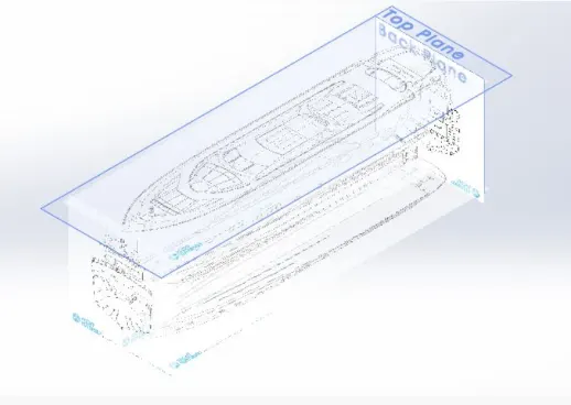
photographic plan or a description of how to make, build or achieve something.
Command Used:-
Here in this we have inserted blueprint images for all views front,top,bottom,back,side view with some offset distance.
HULL
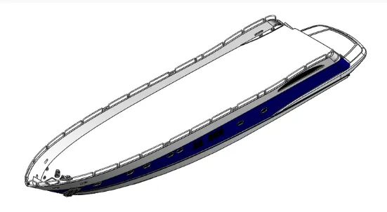
A hull is the watertight body of a ship, boat, or flying boat. The hull may open at the top (such as a dinghy), or it may be fully or partially covered with a deck. Atop the deck may be a deckhouse and other superstructures, such as a funnel, derrick, or mast. The line where the hull meets the water surface is called the waterline.
Command Used:-
- Curve
- Surface Loft
- Surface trim
- Surface extrude
- Surface fill
- Surface knit
- Shell
- Chamfer
- Sweep
- Dome
- Helical spring
- Linear Pattern
- Mirror
GARRAGE DOOR
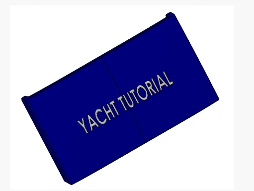
garages have mostly moved to be found in the hull, with garage doors that open out near the waterline.
Command Used:-
- Cut extrude
- Mirror
- Fillet
- Shell
FRONT SEAT

Front seat is used for resting purpose and is located infront of hull part.
Command used:-
- Surface sweep
- Surface extrude
- Surface trim
- Surface Loft
- Surface Fill .
- Surface knit
- Chamfer
- Revolve
- Cut extrude-thin
- Cut extrude
- Fillet
- Mirror
- Dome
MIDDLE SEAT
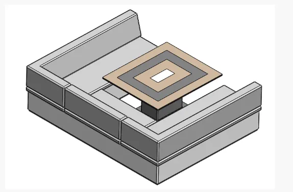
Middle seat seat is used for resting purpose and is located middle of hull part.
Command used:-
- Surface sweep
- 3-d sketch
- Surface extrude
- Surface trim
- Surface Loft
- Mirror
- Surface knit
- Surface extend
- Chamfer
- Revolve
- Cut extrude
- Fillet
- Mirror
- Dome
REAR SEAT
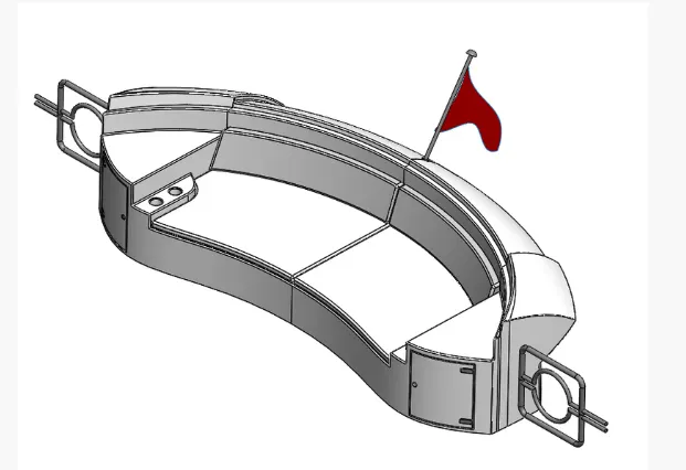
Rear seat is used for resting purpose and is located back of hull part.
Command used:-
- Surface sweep
- Surface offset
- 3-d sketch
- Ruled surface
- Surface extrude
- Surface trim
- Surface Loft
- Mirror
- Surface knit
- Surface extend
- Chamfer
- Revolve
- Cut extrude
- Fillet
- Mirror
- Dome
SUPERSTRUCTURE
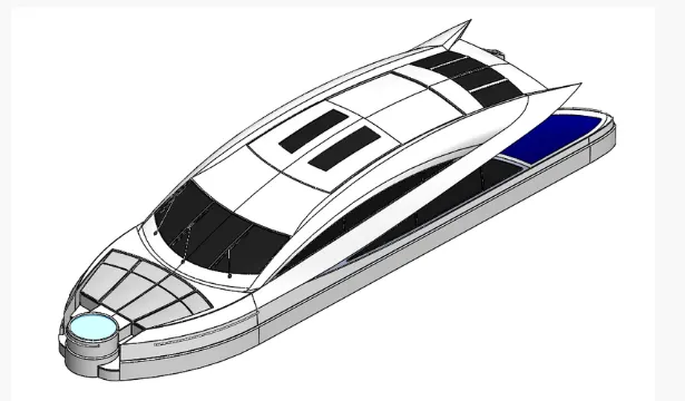
The superstructure consists of the parts of the ship or a boat, including sailboats, fishing boats, passenger ships, and submarines, that project above her main deck. A superstructure is an extended construction of any building or platform that rises above the rest of the building or platform in a distinct manner. Thus, superstructure means to add a construction to an already existing structure. In ships this is the name given to the part of the ship that emerges from the deck.
Command Used
- Surface sweep
- Surface extrude
- Surface extend
- Surface offset
- Split line
- Surface trim
- Surface Loft
- Surface Fill .
- Surface knit
- Ruled
- Curve
- 3-d sketch
- Chamfer
- Revolve
- Cut extrude-thin
- Cut extrude
- Fillet
- Mirror
- Dome
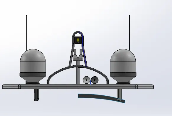
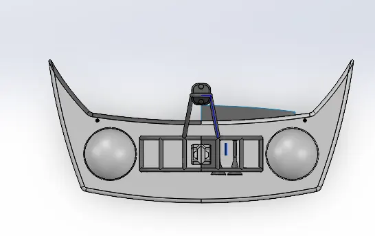
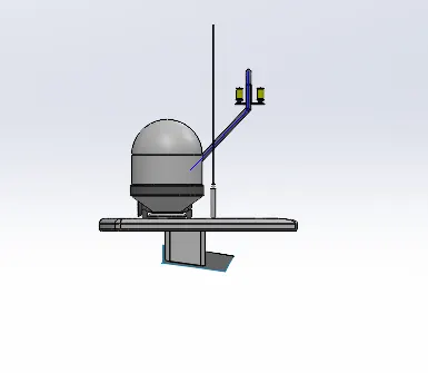
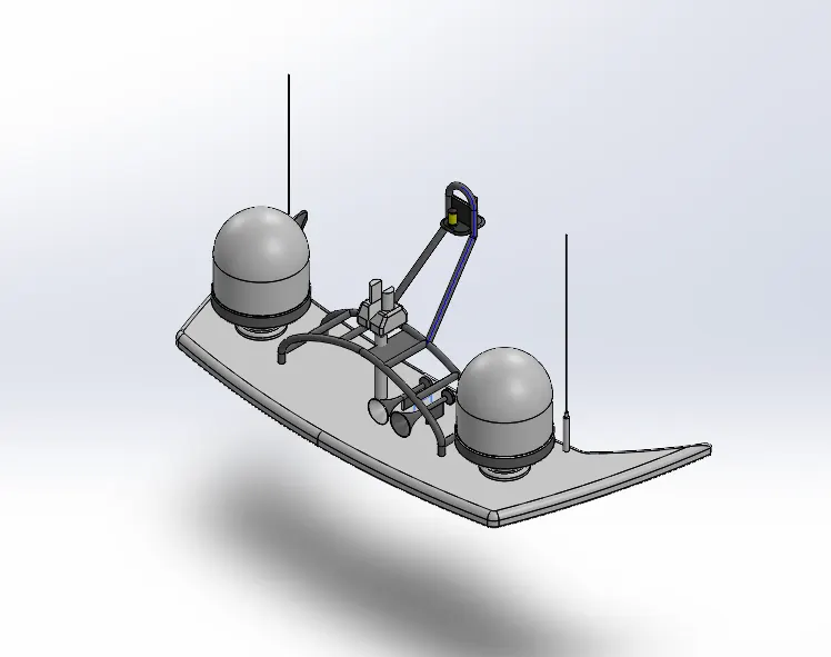
RADAR MAST
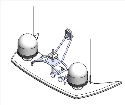
Marine radars are X band or S band radars on ships, used to detect other ships and land obstacles, to provide bearing and distance for collision avoidance and navigation at sea. Radar is a vital navigation component for safety at sea and near the shore.
Command Used :-
- Line
- Circle
- 3 point arc
- Rectangle
- Offset enities
- Convert enities
- Extrude boss
- Revolved boss
- Projected curve
- Extrude cut
- Fillet
- Dome
- Mirror
- Sweep boss
- Chamfer
- Planes
2------------------------------------------------------------------------------------------
Radar_Mast Question
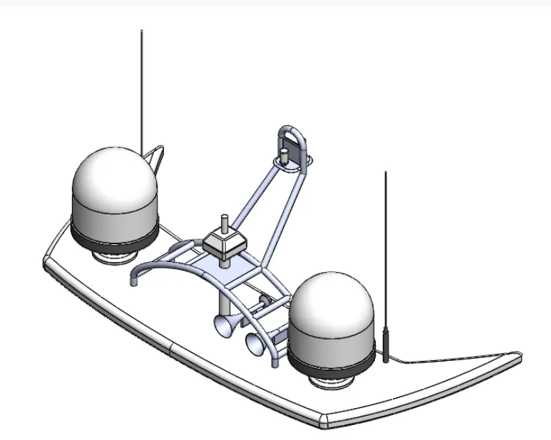
FRONT VIEW
TOP VIEW
RIGHT VIEW
ISOMETRIC VIEW
History-1
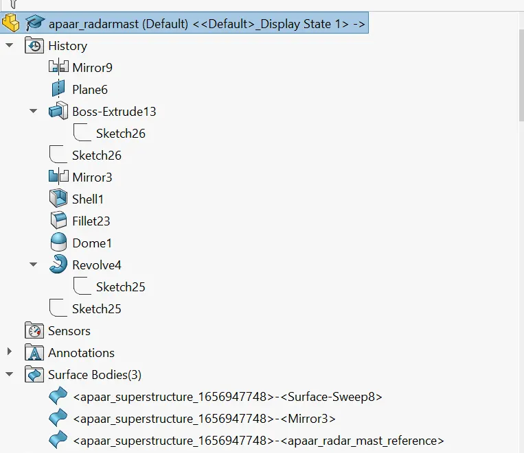
History-2
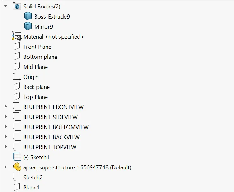
History-3
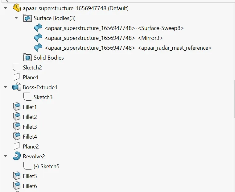
History-4
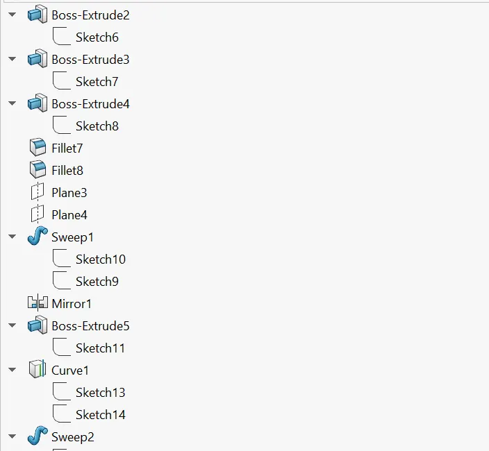
History-5
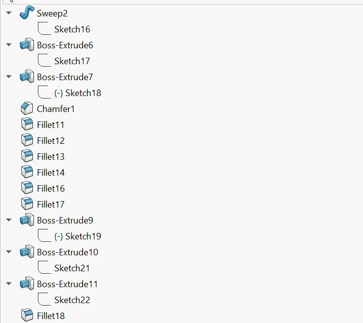
History-6
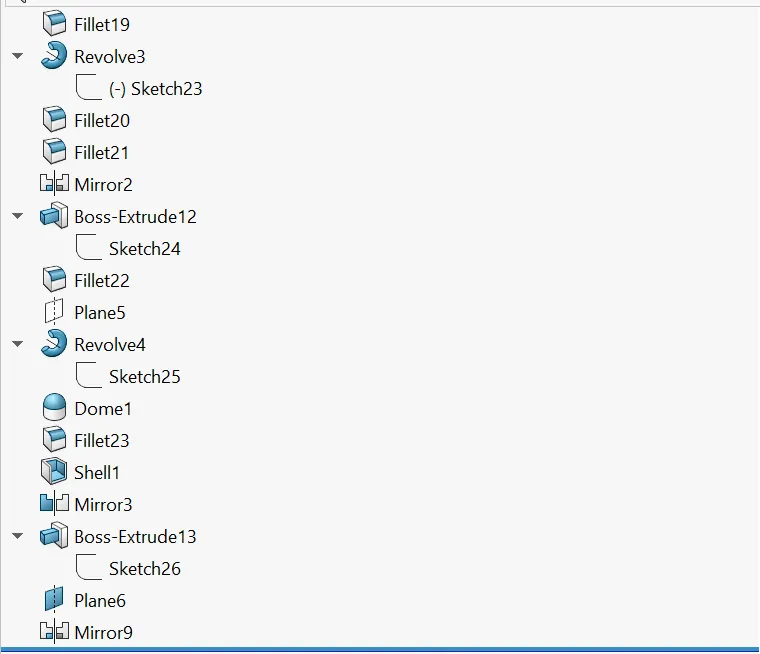
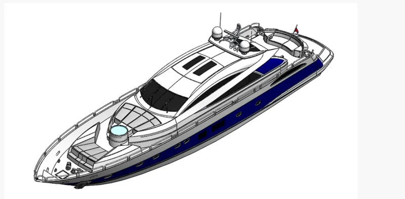
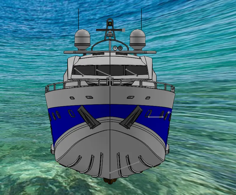
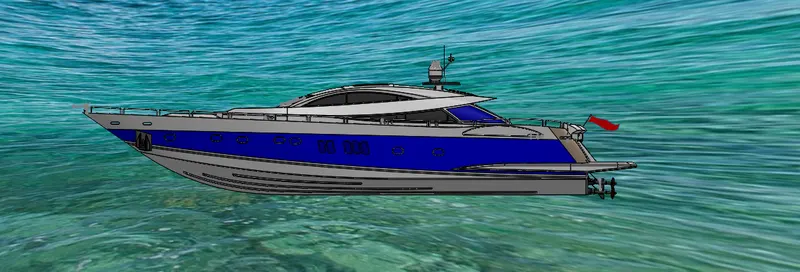
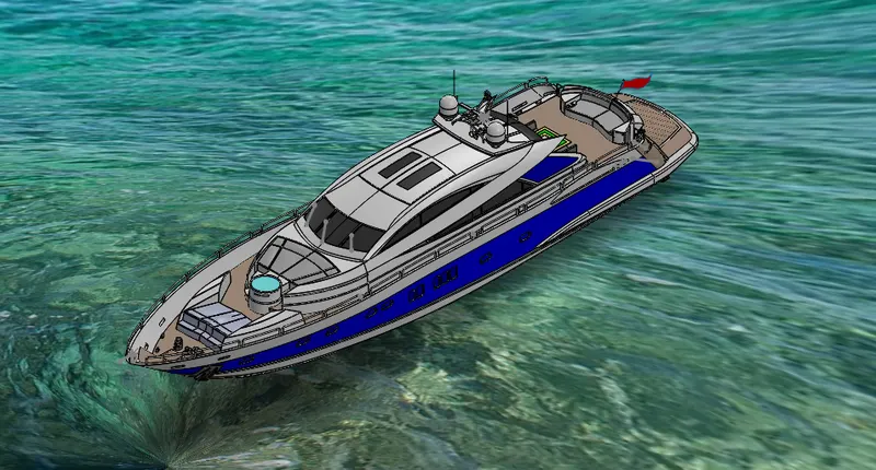
FINAL YATCH ASSEMBLY
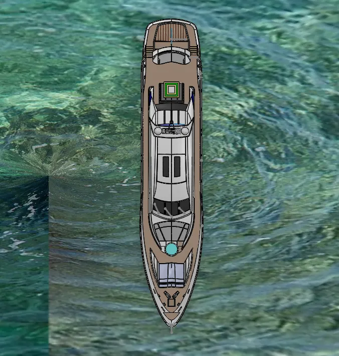
TOP VIEW
FRONT VIEW
RIGHT VIEW
ISOMETRIC VIEW
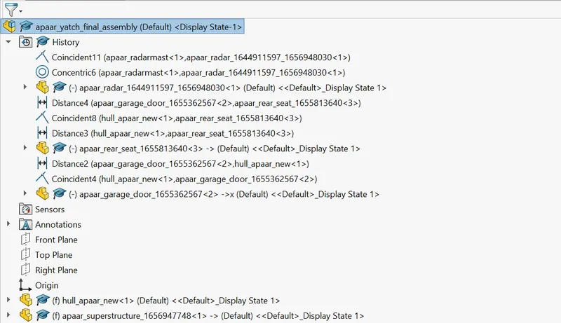
HISTORY-1
HISTORY-2
CONCLUSION
In this project i have learned many tool as i dont know about designing but by doing this project i got confident and interested in designing here i used photo 360 and used rendered tool as edit scene and uploaded background water scene and finished my project with the help and support of skill lync team.
https://drive.google.com/file/d/1CDtMKlvubeLVqPj7_226JEMeowi4s0CJ/view?usp=sharing