Radar Mast & Final Assembly of Yacht
Design, Assembly and Photo-Realistic Rendering of an American Predator Yacht
Objective:
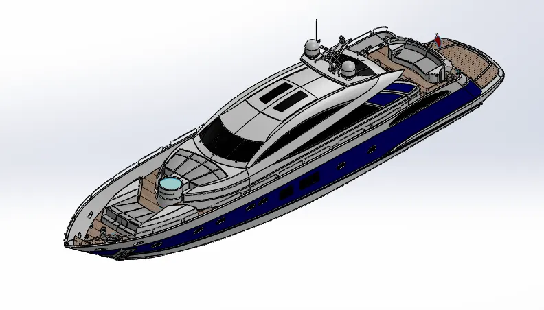
- The objective of the project is to design and model all the parts of an American Predator Yacht and assembling it to create the Photorealistic rendering of the yacht.
Introduction:
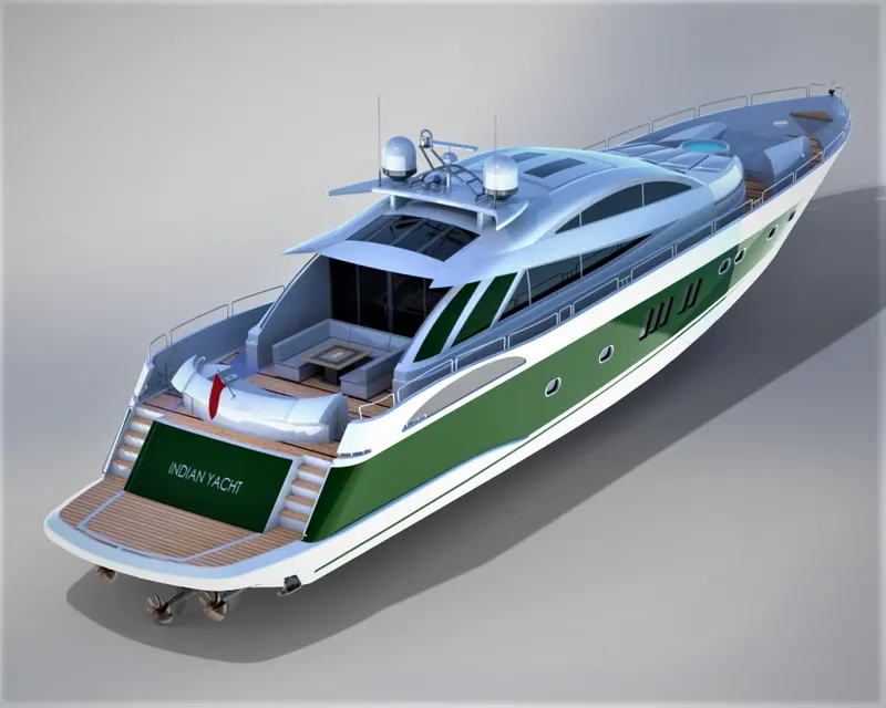
- In this project the American Predator Yacht was taken as a conceptual model, to understand the 3D modelling methodology of Solid modelling and Surface modelling. Each and every part of the yacht was designed and modelled using SOLIDWORKS. Then the modelled parts were assembled by adding proper mates and constraints to create the Photo-Realistic rendered image of the Yacht.
- The SOLIDWORKS is a mechanical design automation application that lets designers quickly sketch out ideas, experiment with features and dimensions, and produce models and detailed drawings.
- Photo-View 360 is a SOLIDWORKS add-in that produces photo-realistic renderings of SOLIDWORKS models. The rendered image incorporates the appearances, lighting, scene, and decals included with the model.
- SOLIDWORKS Visualize is a photo-realistic rendering tool that utilizes our CAD data to create magazine quality images or commercial quality animations.
Design methodology:
- Modelling:
- Hull
- Super Structure
- Propeller
- Garage Door
- Radar
- Radar Mast
- Front Seat
- Middle Seat
- Rear Seat
- Assembly:
- Mating Parts
- Creating Constraints
- Exploded Views
- Rendering
- Decals
- Cameras
- Lights
- Environments
- Back Plates
- Appearances
Description:
Hull
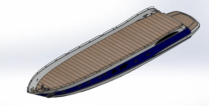
Tools & Features used to make Hull:
- Line
- Spline
- Circle
- Rectangle
- Arc
- Slot
- 3-D Sketch
- Sketch picture
- Extruded Surface
- Revolved Surface
- Lofted Surface
- Surface Trim
- Surface Fill
- Surface Knit
- Delete Face
- Project Curve
- Chamfer
- Fillets
- Reference Plane
- Split
- Split Line
- Extruded Boss/Base
- Extruded Cut
- Mirror
Super Structure
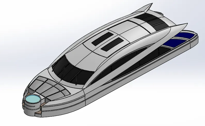
Tools & Features used to make Super Structure:
- Sketch Picture
- 3D Sketch
- Line
- Spline
- Circle
- Rectangle
- Center Point Arc
- Extruded Surface
- Swept Surface
- Ruled Surface
- Knit Surface
- Trim Surface
- Extend Surface
- Filled Surface
- Lofted Surface
- Revolved Surface
- Fillet
- Chamfer
- Project Curve
- Reference Curve
- Convert Entities
- Split
- Split Line
Propeller
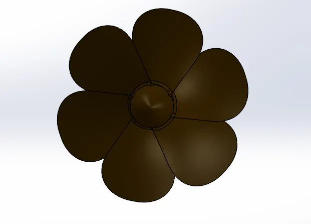
Tools & Features used to make Propeller:
- Spline
- Circle
- Line
- Revolved Boss/Base
- Lofted Boss/Base
- Extruded Cut
- Reference Plane
- Circular Pattern
- Fillet
Garage Door

Tools & Features used to make Garage Door:
- Line
- Spline
- Circle
- Text
- Extruded Cut
- Reference Plane
- Fillet
- Shell
- Mirror
Radar
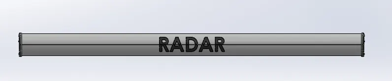
Tools & Features used to make Radar:
- Line
- Text
- Circle
- Point
- Extruded Boss/Base
- Extruded Cut
- Sketch Pattern
- Fillet
- Mirror
- Split Line
Radar Mast
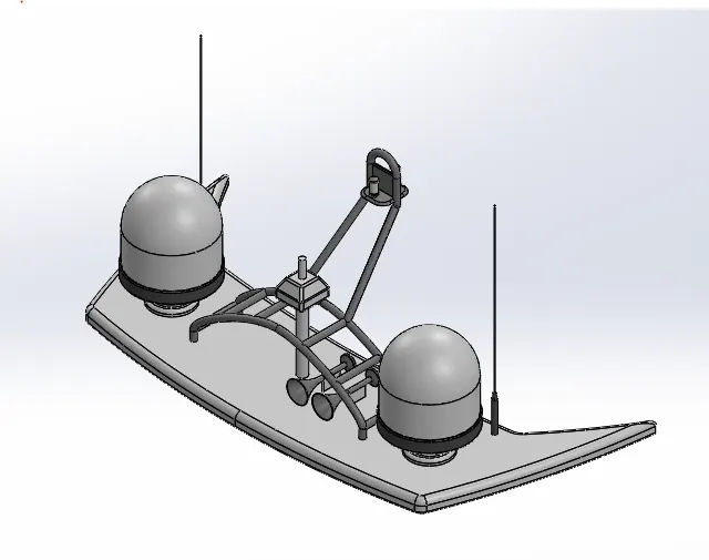
Tools & Features used to make Radar Mast:
- Sketch Picture
- Line
- Spline
- Rectangle
- Arcs
- Extruded Boss/Base
- Lofted Boss/Base
- Revolved Boss/Base
- Swept Boss/Base
- Reference Plane
- Projected Curve
- Fillet
- Mirror
- Dome
- Shell
Front Seat
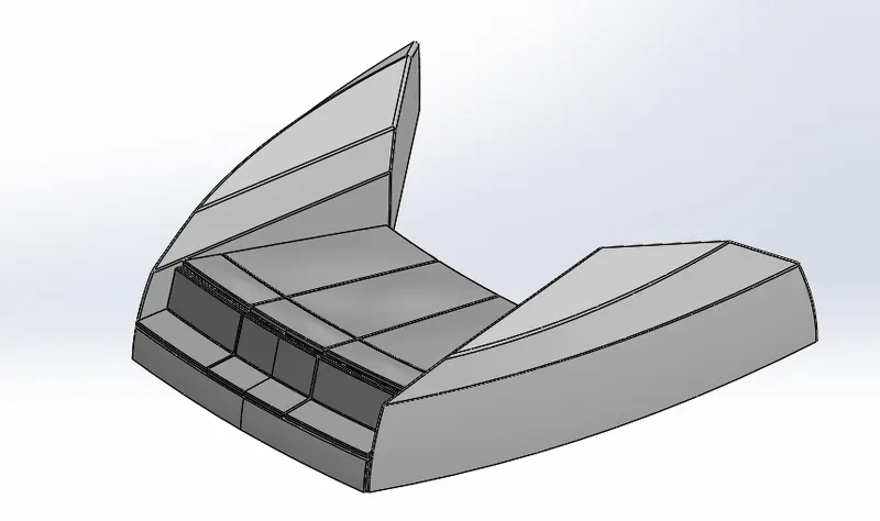
Tools & Features used to make Front Seat:
- Sketch Picture
- Line
- Spline
- Circle
- Arcs
- Extruded Surface
- Lofted Surface
- Trim Surface
- Filled Surface
- Knit Surface
- Swept Surface
- Revolved Surface
- Extruded Cut
- Revolved Boss/Base
- Chamfer
- Fillet
- Mirror
- Dome
Middle Seat
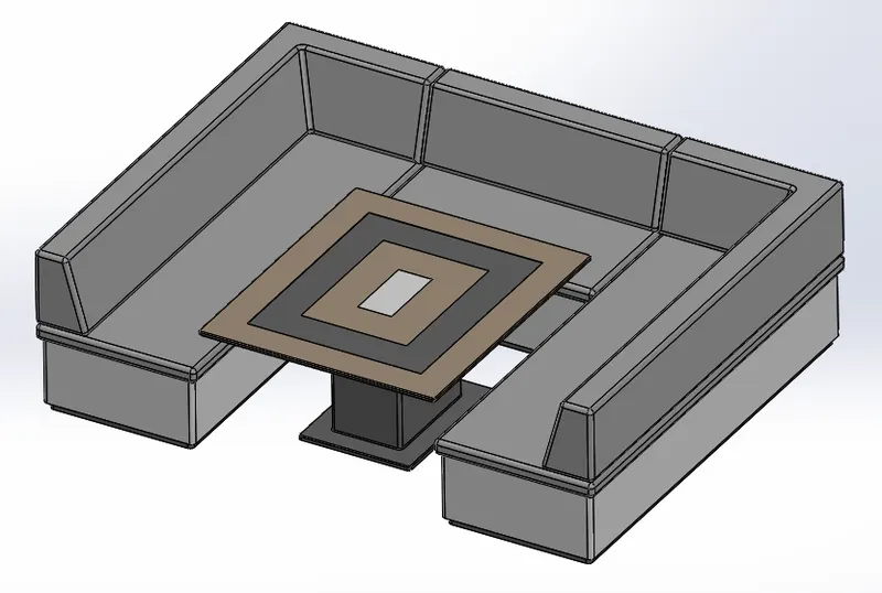
Tools & Features used to make Middle Seat:
- Sketch Picture
- Line
- Rectangle
- Extruded Boss/Base
- Chamfer
- Fillet
- Mirror
- Reference Plane
Rear Seat
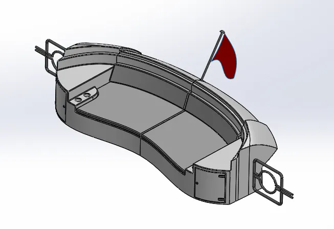
Tools & Features used to make Rear Seat:
- Sketch Picture
- Line
- Spline
- Circle
- Arcs
- Rectangle
- Swept Surface
- Extruded Surface
- Off-set Surface Filled
- Filled Surface
- Knit Surface
- Ruled Surface
- Lofted Surface
- Reference Plane
- Extruded Boss/Base
- Revolved Boss/Base
- Fillet
- Mirror
Assembly:
- An assembly is a document in which parts, features, and other assemblies (sub-assemblies) are mated together. The parts and subassemblies exist in documents separate from the assembly. For example, in an assembly, a piston can be mated to other parts, such as a connecting rod or cylinder. This new assembly can then be used as a sub-assembly in an assembly of an engine. The extension for a SolidWorks assembly file name is SLDASM.
Assembly Commands:
- Smart Mate - A Smart mate is an assembly mating relation that is created automatically.
- Mate - A mate is a geometric relationship, such as coincident, perpendicular, tangent, and so on, between parts in an assembly. Mate group - A mate group is a collection of mates that are solved together. The order in which the mates appear within the mate group does not matter.
- Sub-Assembly - A sub-assembly is an assembly document that is part of a larger assembly. For example, the steering mechanism of a car is a subassembly of the car.
- Insert Components - We can insert multiple instances of the group of components without closing the Property Manager.
Assembly Procedure:
- Import all the parts manually by using Insert Components option.
- Then fix the Hull part by applying the coincident mate to the Top, Right and Front planes of the Assembly and Hull respectively. Then for each part apply the necessary mates required by the Blueprint using Coincident mates, Angle Mates, Distance mates etc.
- Advanced mate was also used wherever required.
Rendered With Environment
Tools & Feature Used:
Decals: Graphics or designs used on chopper bodies.
Lights & Camera: To adjust lightning and camera angles.
Render Preview: To preview the final render before rendering.
Render: To render in required quality and sizes.
Conclusion:
- Thus, the project Design, Assembly and Photo-Realistic Rendering of an American Predator Yacht was Modelled and Rendered successfully using solid works software.