Radar Mast & Final Assembly of Yacht
RADAR MASt

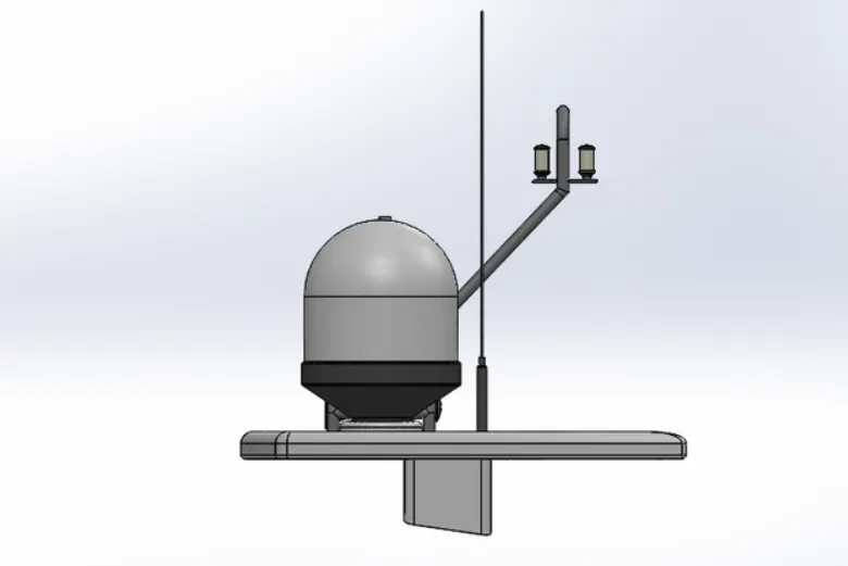
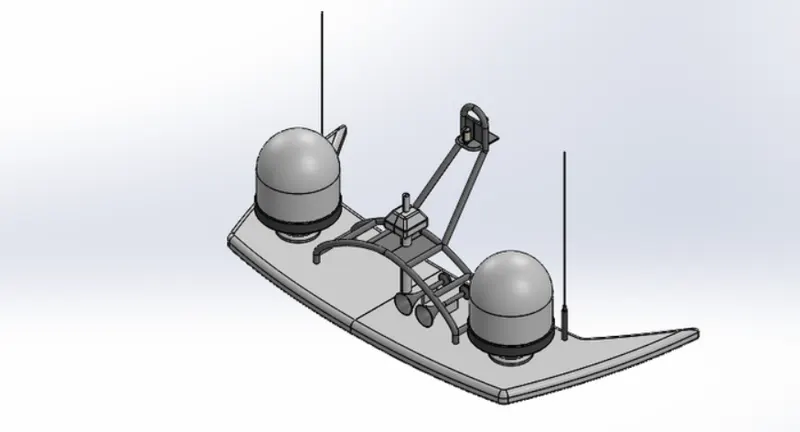
FINAL ASSEMBLY OF YATCH
CHAPTER 1
INTRODUCTION BY : ARAVIND RK
BY using solidwork software an cad modeling we are made so many models based on mechanoical ,electrical etc all in 3d surface designing we made yatch by using thies software of many miny parts all this miny parts were completed final assembly should b done
OBJECTIVE
Assembling of all the parts can b done
all the features can b notice in the software
photoview an blueprint are also include in it
CHAPTER 2
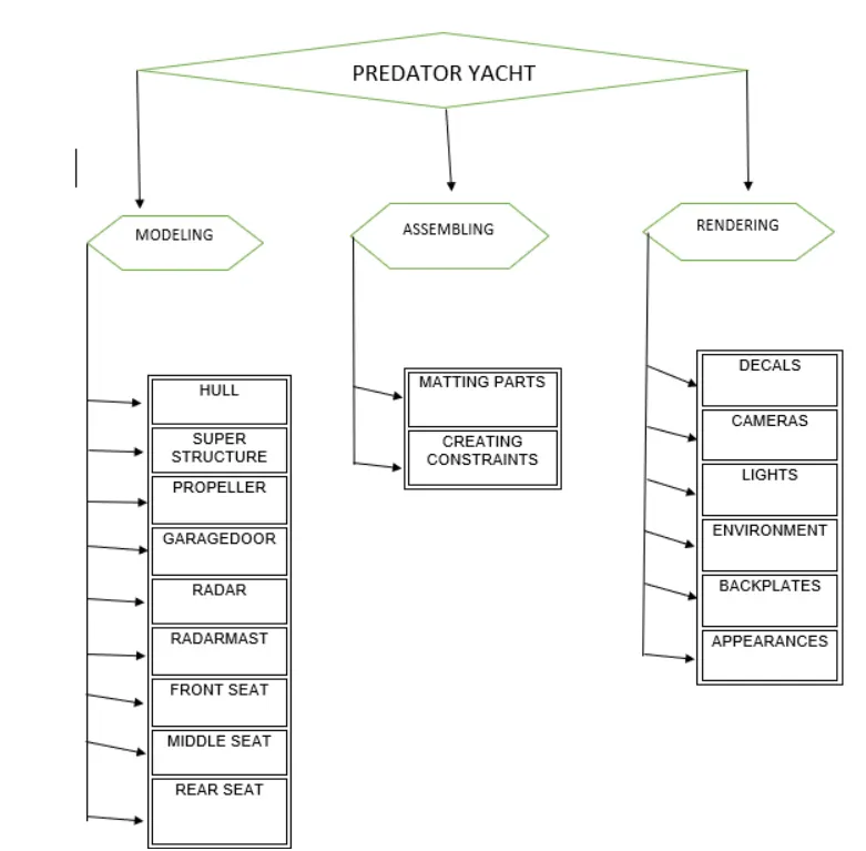
METHODOLOGY
CHAPTER 3
AND PROPERTIES
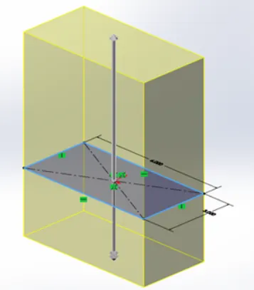
EXTRUDE BOSS
In the blong we wilbe covering the extrude bass bass future this is one of the most common and universal feature used the 3d modeling this is a handy feature for creating 3d modeling with soild worrk using the model 2d sketch create you are ready to turn 2d sketch into the 3dsolid work
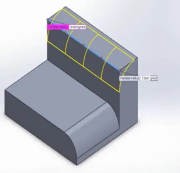
FILLET
Fillet create internal an external surface face on the part you can filled all edges of a faceselect sets of faces select edges or edges loops
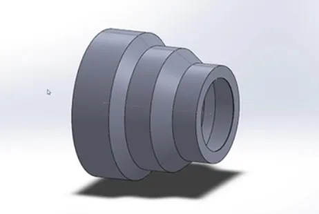
REVOLVED BOSS FEATURE
Revolved boss feature add or remove material by revolving one or more profile around a centerline you cancreaterevilved boss bases revolved cut or revolved surfacethe revolved feature can be asolid
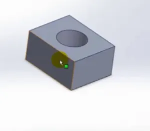
EXTRUDE CUT
using extrude boss base model crete in the extrude boss bass belong wewil modify the 3d block to include a circle feature by removing material the extrude cut feature can be foundonthe feature tab in the interface
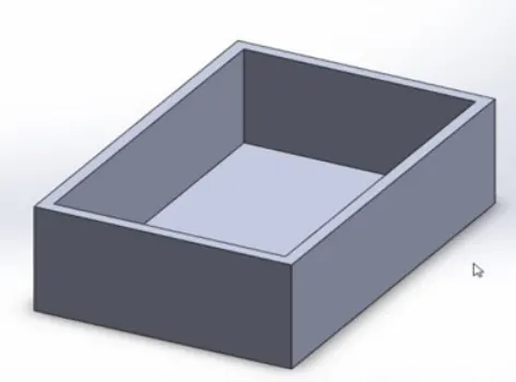
SHELL
THe shell tool holow out a part leaves open the faces you select and create thin walled feature on the faces if you do not select any faces on the model you can select the solid part create close holow model shell
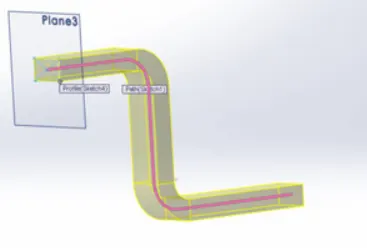
SWEEP BOSS/ CUT
Sweep is the one feature in solid work that used to sweep a close profile along close r oprn path in this sesion we atre going to use a simole 3d exercise to demonstract the use of the sweep common
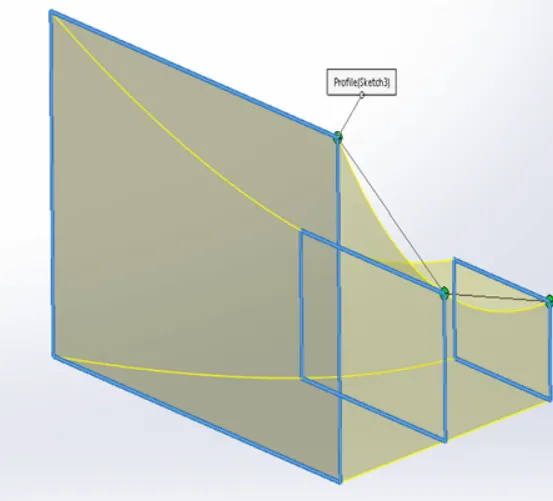
LOFT BOSS/CUT
Loft create a feature by making transmission betwwen the profile. a lot can be a bass boss cut surface create a lotusing two more profile only the first andthe last profile can b point all sketch entities including guides curves and profile can be contain in a single 3dsketch
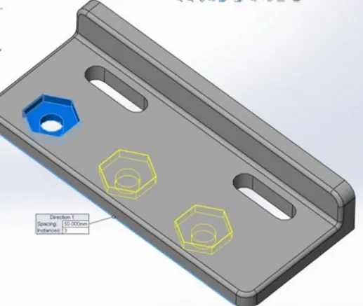
LINEAR PATTERN
This pattern is uses to create the great the way to make the grid of hole ormultiple bodies very quick this tool is easy to save a lot of times use linepattern to create mulipleinstand one or more feature
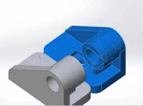
MIRROR
mirror is the another way to solid work can be create a copy of exixting object in the most cases you wil have to create your own plane to have the mirror done on the wayneed
PROJECTED CURVE
Tools are caled as projected tool prijectd curve take any sketch and transfer it over to another sketch or face you can then use that sketch for creating feature to even to splite a body the project curve feature is more like the split line tha the featureit can do everything the split line
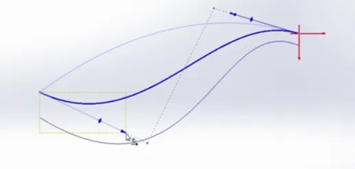
REFERENCE GEOMENTRY
IT define the shape or form of the surface or a solid work reference geomentry include items such as plans axes coordinates system an points plain are use in loftsnand sweeps axis is used as a circular pattern
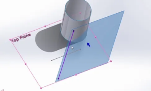
DOME
IT provide a tool called as dome can create a dome 3d structure part an shape the used of dome command is very easy the parametersnin the dome property manage include face to dome select one or more planer non planner faces
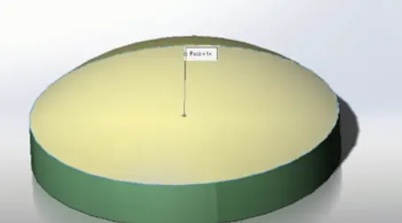
SPLIT
USE the split feature to create multiple part from an existing part can create seperate parts files and from an assembly from new part .can solit line one or more solid surface line or surface bodies to split surface trim extend past the bodies
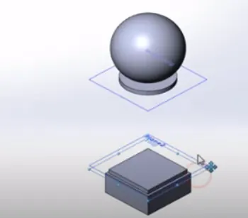
MATE
Mates create geomentry relation between assembly component as old mates .define the allowed direction of liner or rotation of the component you can move a component within its degree of freedom
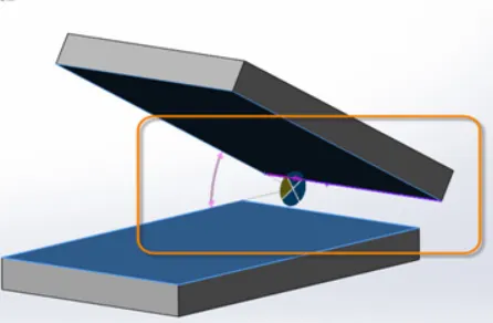
CIRCULAR PATTERN
Circular pattern is create multiple instand of one ormore feature that youcan space uniformly around an axis you can create circular pattern sysmmetrically or asymmetricaly in both directionfrom the seed geomentry
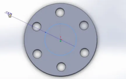
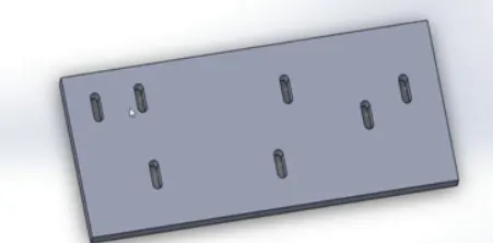
SKETCH DRIVE PATTERN
Using this future point with in a sketch you can specify a feature pattern the seed feature propagates through out the patytern to each point in the sketch you can use sketch drive pattern for holes or other feature instance sketch drive pattren crete the pattren using only the geomentry on the feature
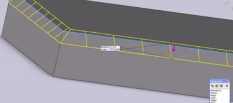
CHAMBER
Chmaber tool create a beveled feature on feature on select edges or vertex can create particular chamber off face chamber by specifying length model edges
SURFACE EXTRUDE
We can create model that include 2d or 3d faces and knit the extrude surface to surrounding feature and canextruct surface at one end or at both ends
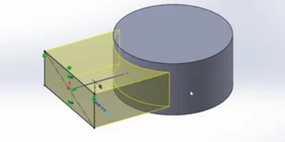
FILLET SURFACE
The fillet surface feature construted a surface path with any number of sides within a boundry defined by exixting model edges model edges
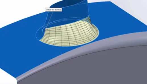
SURFACE TRIM
We can used surface plain orsketch as a trim intersecting surface we can qlso used asurface in conjuction with addition surface as mutual trim surface following option
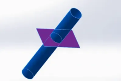
SURFACE EXTEND
Surface by selecting an edges multiple edges oe a face edges the surface extends along the plane of the edges the surface extends alomg all edges of the surface
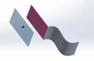
SURFACE SWEEP
Edes an curves directely from models can sweep profile the profile may b open or closed for a surface feature the path can beopen or close and can be a set of sketch curves conditon in one sketch
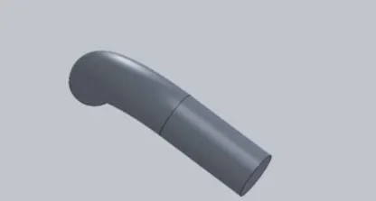
SURFACE OFFSET
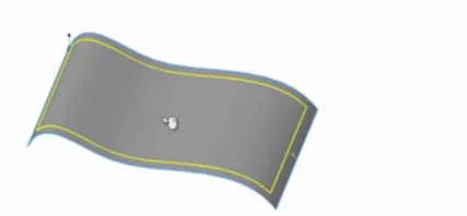
A command techniqe for advance surface modelling is used the surface offset command the command gives user the option to see and remove any surface that command be offset
CHAPTER 4
FINAL ASSEMBLY OF YATCH
HULL
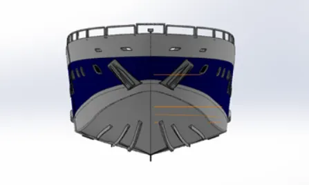
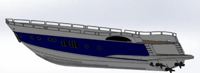
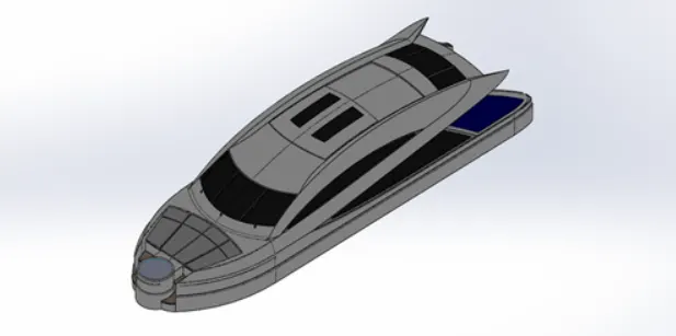
Ahull is the watertight body of a ship orboat the hull may oprn at the top or it maybe wholly or partiaaly coveed with a deck the line where the hull meets the water surface is known as water line the hull of a ship is the most notable structure of theship to define that the hull itcanbe said that it is the watertight encloser of the ship
COMMAND USED
IN SKETC
line
spline
circle
arc
IN FEATURE
chamber
fillet
splite
splite line
MODELING PROCEDURE
First step create the blue print of it
shell is used to create the shell in the front position of the hull
then the duck surface is used to create the extruded option
required chamber an fillet us3d to do the curve saurface
SUPER STRUCTURE
A is an upward extraction of an existing structure above a base line called ground level and it useally serves the purpose of the struture intend is used
COMMAND USED
IN SKETCHING
sketch picture
3d sketch
line
circle
IN SURFACE
extruded surface
swept surface
ruled surface
knit surface
MODELING PROCRDURE
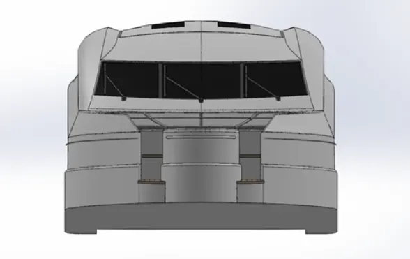
The hul was improved and the superstructure was model the left edge wasfilled by the ruled surface
the superstructure consists of two surface body an 5 solid body
it generated were knitted together from qa solid body
one of the surface is deck surface the another is used to fixe the rador
PROPELLER
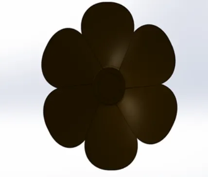
There can b a more than 2 propeller most important in ship main working of the propeller is usedto move the ship forward direction
COMMAND USED
IN SKETCH
spline
circle
line
IN FEATURE
Extrude cut
reference plain
fillet
MODELLING PROCEDURE
The centre positon of the propeller was sketched and revolved
blade were sketch by reference plain
centre circle were removed by circular pattern
GARAGE DOOR
A garage dooris the biggest door it can open manually or by using electric motor the mechanism is use in the door is spring load it avoid the heat pass throught the bost
COMMAD USED
IN SKETCH
Line
spline
ciecle
text
IN FEATURE
Extrude cut
fillet
shell
mirror
MODELLING PROPERTIES
The solid body split whilemanufaturing the hull was improved the model ofgarge door
using extrude cut chamber face for the door was produced
then by using the shell feature the soildbody for the was formed
RADAR
Marine rador x band s band rador on ship used to detect other land obstacles on ship to provide bearing and distance for collision avoidance at sea they are electronic navigation instrument that used to rotating antena to sweep a narrow bwam
COMMAND USED
IN SEKTCH
line
text
circle
point
IN FEATURE
fillet
mirror
split line
MODELING PROCEDURE
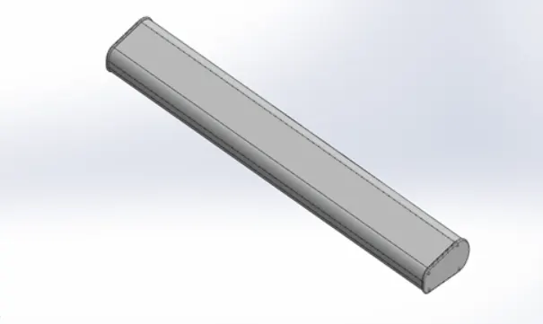
Draw the requirement sketch body of the rador
create using extrude bass an bass
sketch pattern four doted holes were create
rotorhas a circular slot was created using the extrude cut
RADAR MAST
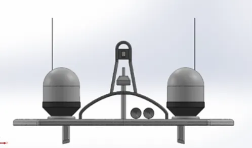
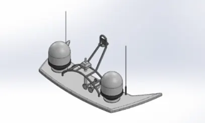
Mast is the vertical ship structure on the top od bridge forward forcast toward the ship bow they a made by the high tensile steel with the addition rigidity depending on the size of derricks it holds
COMMAND USED
IN SKETCH
Sketch picture
line
spline
arts
IN FEATURE
Fillet
mirror
dome
shell
MODELLING PROCEDURE
The body of the radar was madeby extrude boss bass,revelute boss bass
the antenna of the rador was created usig the extrude boss bass
after the fillet and chamber wereapplied
in the end the part was solved by applying the apperance
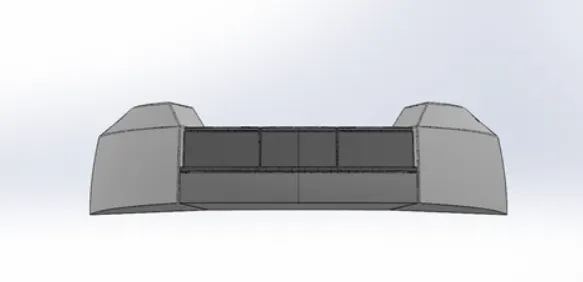
FRONT SEAT
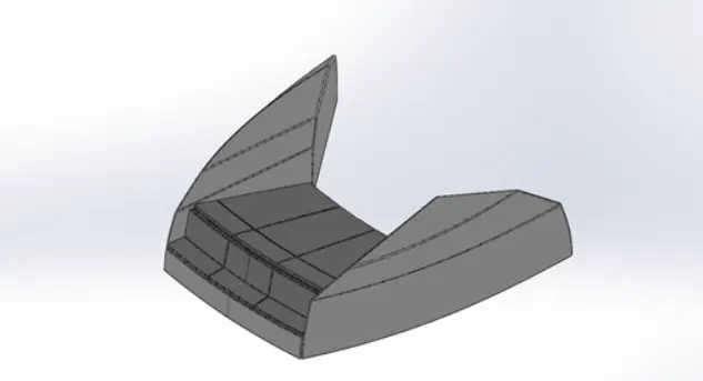
Front seat feature two connect sats that are built back an back from one on the another thay build in storage unit under it lounge seat can also fully fecline right back to make easier
COMMAND USED
IN SKETCH
line
spline
circle
arcs
IN SURFACE
Trim
fillet
knit swept
IN FEATURE
Chamber
fillet
mirror
MODELLING PROCEDURE
The front seat also created by using blue print
first hals was modelled an nexthalf was mirrot
theseat was placed brfore the superstructure facing
then the required fillet and chamber were created
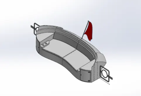
MIDDLE SEAT
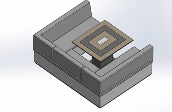
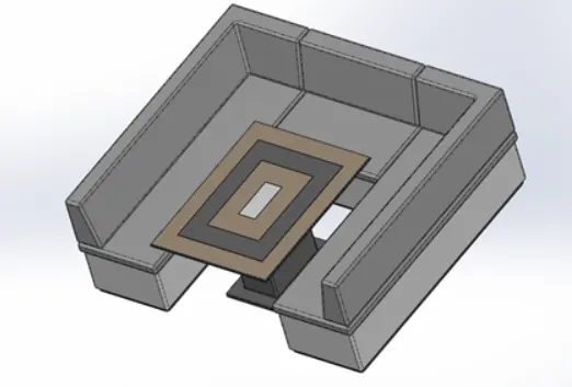
The middle seat is gust adjusted from the super structure it was provide by luxury table have a meetimg to
COMMAND USED
IN SKETCH
Sketch picture
line
rectangle
IN FEATURE
Chamber
fillet
mirrir
MODELLING PROCEDURE
The middle seat was created using extrude boss bass
applying chamber and fillet as wanted
all the surface must be together using option knit surface
at last the part was solved
REAR SEAT
IT placed at the end of the deck surface the rear seat consists of locker eacks an steel doors for stairs
COMMAND USED
IN SKETCH
LINE
sp line
arcs
rectangle
IN SURFACE
Knit
ruled
loften
IN FEATURE
Reference
fillet mirror
MODELLING PROCEDURE
The chief body of the reatr seet was modelled with the help of swept
the settel gate was design to cose the parivular area sweep struture
the required fillet an chamber were created before mirror
to reomove the gap all the surface must b knitted together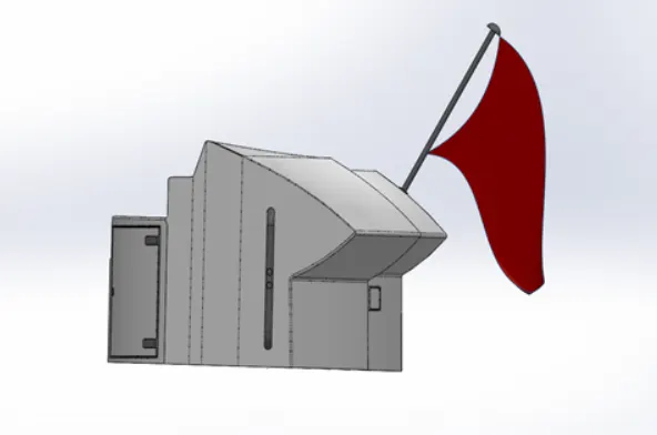
CHAPTER 5
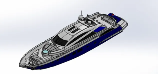
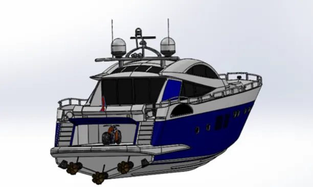
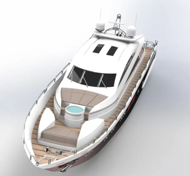
ASSEMBLY
CONCLUTION
- THUS BY USING SOLID WORK THE PART MODELING AND APPERANCE WERE SUCCESFULLY DESIGH
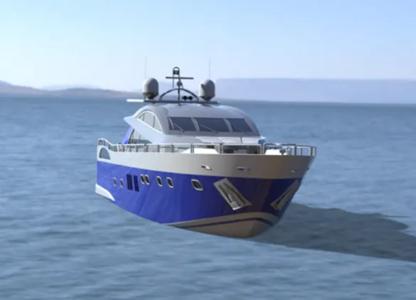
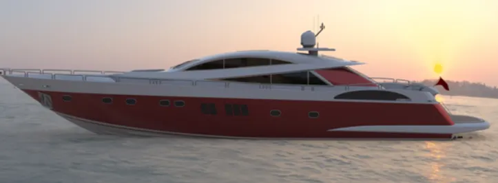
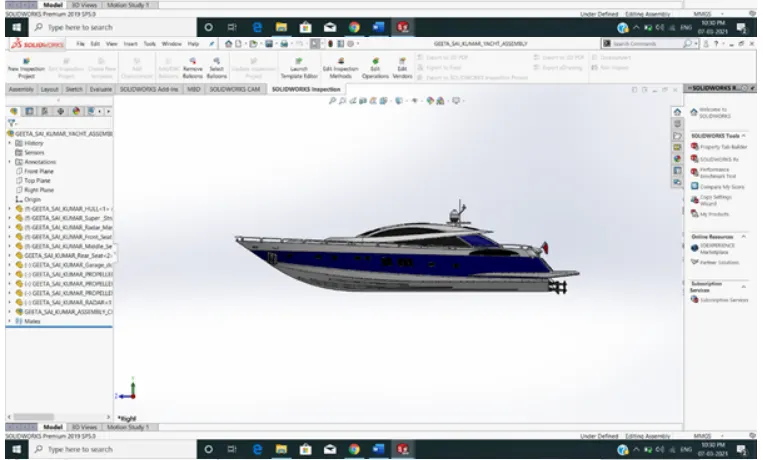
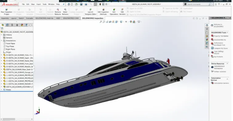
- USING SOLID WORK THE SUNSEEKER PREDATOR YAYTCH WAS DONE