Photo Realistic Rendering
PHOTO REALISTIC RENDERING
BY ARAVIND RK
INTRODUCTION
This report briefely explain about the design of american chopper using soiid work 3D modeling ,cad software from intial stage to final stage solid modeling ,surface modeling tools explained
OBJECTIVE
To learn the basic of solid work 3d design etc
Design american chopper using solid work
Create all the parts an final assembling
To know about all the feature avaliable in solid work
part modeling
part modeling is the process of which modelling of a component in 3d by using 2d sketch using tools sketch construction
methodology
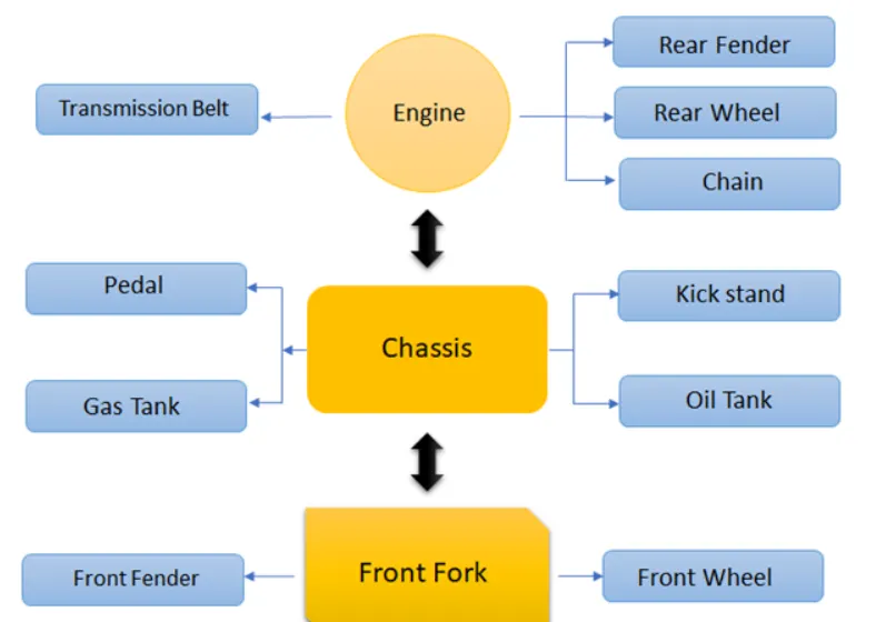
COMPONENTS TO DESIGN
Transmission belt
kick stand
front fender
rear fender
chain
oil tank
pedel
front wheel
rear wheel
front fork
chassing
engine
gas tank
FEATURES AN TOOLS
using tools wil be mention below the models
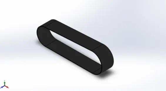
TRANSMISSION BELT
COMPOUNT DESCRIPTION
Transmission belt is used to transmit the power from one end to another end with out lossing of any power
FEATURE
Boss exclude - according to the sketch plain used to explain the 3d model
fillet- used to create the round edge from sharp dege
CONSTRAINTS USED
midpoint
tangent
TOOL USED
line tool - draw stright line horizontal vertical
sp line - to draw cruve line
METHODOLOGY
The aim to study was to develope the efficient an realistic surface optimisation techniqe for the design of belt drive for power out put of the drive in machinery design
IMAGE
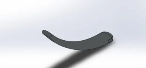
KICK STAND
COMPONENT DESCRIPTION
Kick stand is used to supporth the chopper to lean on ground properly kisck stand is an supporting mechanism
FEATURE
spline - single solidpart into 2solid part
fillet - used to make round edges
extract boss base - expand the object in 3d
CONSTRAINTS USED
coincident
midpoint
TOOL USED
ellips - elliptical sketch
spline - used to create the curve line
centre point - used to make a rectange base on centre point
METHODOLOGY
Using line and arc constrction making a sketch with the giving dimension offset the sketch with offset entities after get dimention sketch make extrude using boss extrude
IMAGE
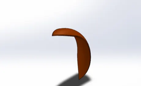
FRONT FENDER
COMPONENT DESCRIPTION
Front fender is used to avoide the dust,mud,stone flow while tyre running in high rpm it reduce tyre demages
FEATURE USED
revolute - used to create cylindrical ,circular 3d part
split - single part into to
dome - make dome shape extrude including ellipitical dome
TOOL IUSED
3point arc - used to draw a arc with the centre point as the reference point an arc
dynamicmiror - mirror the entire frsture to the plain selectfor meroing
trim entities - delete the unwonted lines an curves
METHODOLOGY
create the 3 point the arc as the dimention with the offset usingthe extent entities to meke complete the sketch
IMAGES
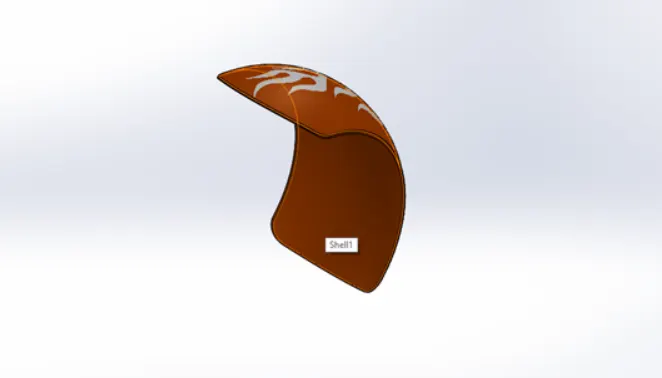
FEAR FENDER
COMPNENT DESCRIPTION
It present back side tyre it also used to avoide the flow of mud,dust,liquid while the tyre run in high rpm
FEAURE USED
shell - hollow space in solid part by selecting the outer wall ofthe solid part
fillet - create round edge
CONSTRAINTS USED
horizontal vertical
TOOL USED
Trim entities - used to trim unwanted lines
spline - to create the 1 solid part to another
METHODOLOGY
Create 3 point arc at mid point of rear fender off set a line at the given distance at he end of the arc line draw an extent entities
IMAGES
CHAIN
COMPONENT DESCRIPTION
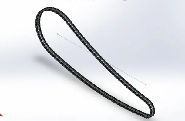
Chain is used to transmit the power from engine to the rear wheel tooth while acceleration the chain wil tramist required power
FEATURES USED
Extrude bossbass - used to expand the object 3d
fillet - create round edge
curve - spline used to draw the curve
CONSTRAINTS USED
tangent
coincident
concentric
TOOL USED
circle- used to draw ciecular sktch
block - particular sketch as block that we ca draw at any time
METHODOLOGY
Started with the two circle with the located as constructio line reference afterthe deaw a 3 point curve which is tangent with the ciecle with the specific then trim additio lines create the chain pin block
IMAGES
OIL TANK
COMPONENT DESCRIPTION
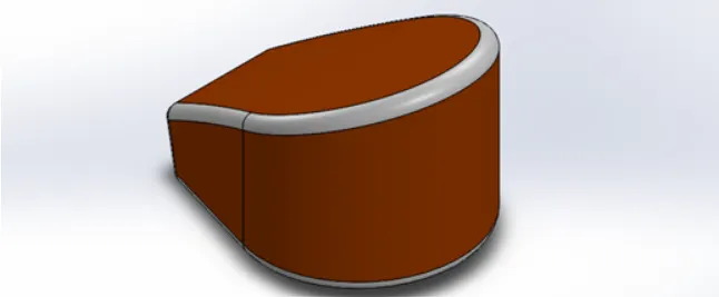
Oil tank is used to maintain the constant temperature in the engine during ignition system for long time engine block wil wil heat to reduce the heat oil tank system is used
Features used
combine - used to make integration of two solid parts which intersect each other assame as solid part
fillet - to create the round edge
Constraints used
tangent
coincident
Tool used
Arc - draw the arc centre point as the reference
fillet - circular curve
Methodology
start with top plain making line and make tangent arc coincident with construction line make stright line with the sketch point then make themid point to make the oil tamk extruct after make the combine both aline
IMAGES
PEDEL
COMPONENT DESCRIPTION
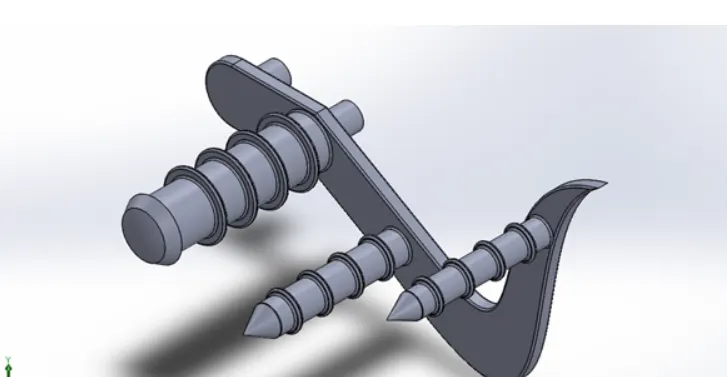
Pedel is used to keep the leg in it to safe drive to prevent the foot contact with road an confortable drive
Feature used
fillet - used to create the circle path of the edges
dome - make dome a edges shapes extrude including ellipitcal dome
champer - edge sharp to make angle tapping
linear pattern - linear pattern is to make a solid feature pattern in path as liner
CONSTRAINTS USED
tangrnt
coincident
TOOL used
offset - make the same sketch at a selected point give dimention
line tool- used to draw the stright construction line and tangent
METHODOLOGY
making a fully defined sketch fillet with the relation and sketch ended with the fully define sketch as link to get a exact dimenton
then extruct a fixing pin using a contour line make pedel frame same as that an make a revolute of leg rest from the sketch
IMAGE
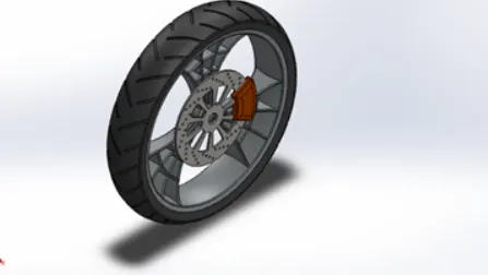
FRONT WHEEL
COMPONENT DESCRIPTION
Wheel is an locomotive component for every vechile is used to balance the vechile wight an smooth move it build by hard rim an lylon tyre
FEATURE USED
Fillet - is usedto make a round edges
Linetool - used to draw stright line ,construction line ,tangent arc
3point arc - centre as a reference draw the arc
spline - curves an geomentry shapes
trim - used to trim the extra line
chamber - edge sharp edge to make angled taperring
circular pattern- 3d feature in to circle pattern
CONSTRAINTS USED
Coinsident
midpoint
horizontal
vertical
tangent
TOOL USED
CIECLE - draw a circular sketch
block - particular sketch as block than we can get a sketch as block able to insert the geomentry
METHODOLOGY
Started with two circle which located as construction line referenc after that draw a3 point curve which isntangent with two circle with specific radius ten trim additon lines create the chain pin block by using the block to make the path with the curve which is drawn
IMAGES
REAR WHEEL
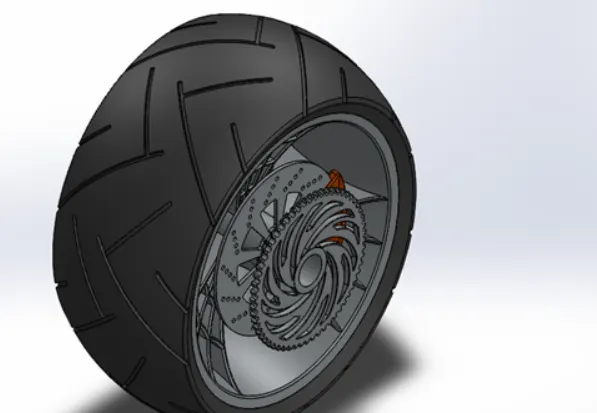
COMPONENT DESCRIPTION
Rear wheel is also a locomotive system .but some bigger that the front wheel to avoide the skitting while in turning i build by rim an nylon tyre
FEATURE USED
EXCLUDEBOSSBASS - 3d according to the sketch
REVOLUTE BOSSBSSS - cylinder to 3d sketch
REVOLUTE CUT - is used to cut the extracylindrical surface
CHAMBER - edge shsrp
CONSTRAINTS USED
Coincident
mid point horizontal
TOOL USED
FILLET - Make round edges
SPLINE - draw curve lines
TRIM - it delete extraw lines
EXTENT ENTITIES- I used to draw the line alonr the sketck tonext line
METHODOLOGY
For rear wheel it consists of tyre,rim,disk plate etc
RIM- Is made of steel in circular pattern
TYRE- is made of lyon
DISK PLATE - made of steel
IMAGES
FRONT FORK
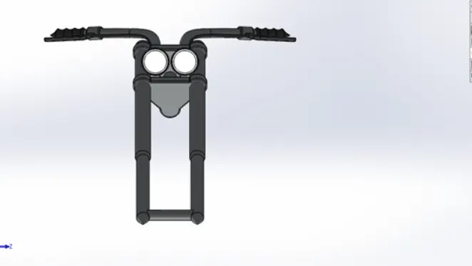
COMPONENT DESCRIPTION
IT consists of two narrow tube consists of two shock absorver along with the axis of front wheel an head
FEATUREUSED
REVOLUTE - is used to make cylindrical r circular 3d exclude along with the reference
DOME - used to draw dome shapeelipiticaldome
SPLIT - singel part in to two
COMBINE- integrated of two solid part which intersect each other
MOVE COPY BODY- move one place to another place
SWEEP - one kind of fully define sketck along with the same poth
CONSTRAINTS USED
mid point
coincident horizontzl
TOOL USED
PROJECT CURVE - SPECAL TOOL TO MAKE easier projector ombine a curve from different plainin to single palin
CONVERTENTITIES- this tool used to make sketch according to the plain which under sketch makes a track a single line
methodology
starting with the long barrel which wheresusponsion located make revolute futute as the sketch front plain
front top plain extrude the centre part 0f fork ehere the light and sppedmetro located offset frpm samd distance
IAMGES
CHASSIS
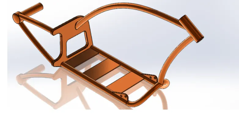
COMPONENT DESCRIPTION
Chassing is the main part in the vechine it with stand all the weight of the component like gas tank, engine,pedel fuel tank ,head etc
FEATURE USED
MIRROR- mirror is used to make same same model as per the another
SWEEP- sweep the any kind of path fully define sketch along with the path
CHAMBER- edge sharpe edge to make angular taping
FILLET - used to make round edge
CONSTRAINTS USED
Mid point
horizontal
tangent
TOOL USED
CONVERT ENTITIES - track of nest line
ciecle- USED to drew the ciecular path
METHODOLOGY
NEED of reference blue print for make chassies by importing chooper blue print using images sketch feature after importying make with of important images splines to make project curve bottom part of chassies along curve
IMAGES
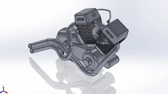
ENGINE
COMPONENT DESCRIPTION
ENGINE have a fuel compuction chamber to generate the power by using this power the vechile used to move
FEATURE USED
MIRROR- it used to make asame point an same reference to create another to reduce the time
sweep - any kind offully define sketch along te=he path
combine - integrated with each other
chamber- edges sharp an angle tapping
linear- solid feature pattern in path as liner
constraints used
coincident
concentric
horizontal
vertical
TOOL USED
filet- create round edges
line tool- stright line constructionnline tangent line
offset- draw the same sketch select the point reference
composite curve - two curve into single curve
methodology
engine part modelling need to reference images same as chassins after using engine
blueprint make the line and tangent for pully used to drive after that making an extrude from a new plain from the reference of make a engine block using cut this fings in engine and make mirror afterthe air ontake usingrevolute
IMAGES
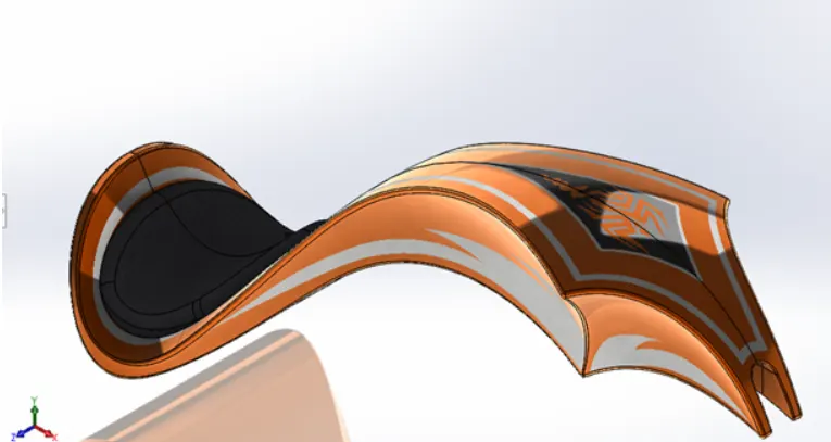
GAS TANK
COMPONENT DESCRIPTION
gas tank is usde to store the fuel from the fuel tank required amount of fuel wil pass to compotion champer
FEATURE USED
SWEPT SURFACE - make a surface along with a path curve is drive
BOUNDRY SURFACE- Between two finishing surface
LOFT SURFACE- make loft in betwwen two profilealong with guide path
KNITSURFACE - USED TO MAKE KNITZIPPED TWO SURFACE
SHELL- space in solid part by selecting outer wall of the solid part
CONSTRAINSTS USED
tangent
coincident
TOOL USED
PROJECTIVE CURVE- special tool to make work easier projects used to combine a curves from different plain in to single plain
CONVERT ENTITIES- sketh according to palin which under sketch make trace of single line
METHODOLOGY
IN gas tank which is make an surface extrude along with blueprint by making sweep surface extrude making a tangent spline curve along with sweep path to make a outer tank wall
IMAGES
ASEMBLYOF CHOOPER
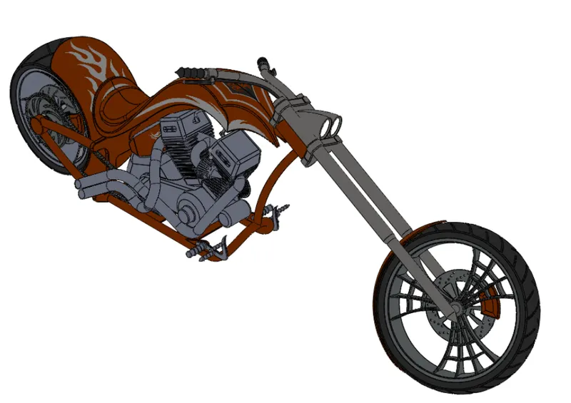
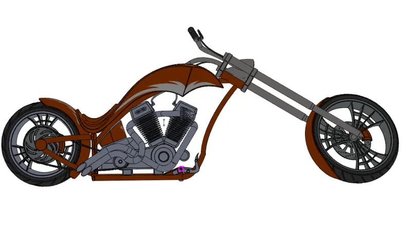
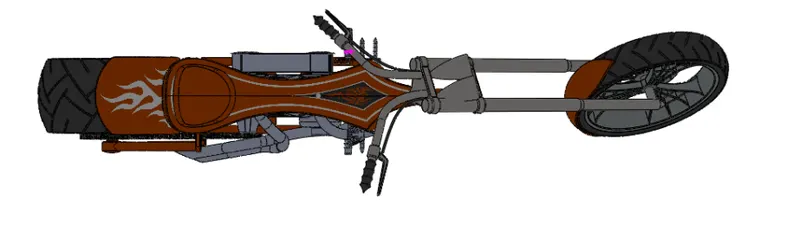
RENDERING IMAGES
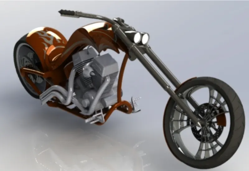
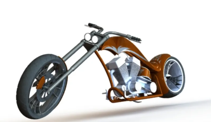
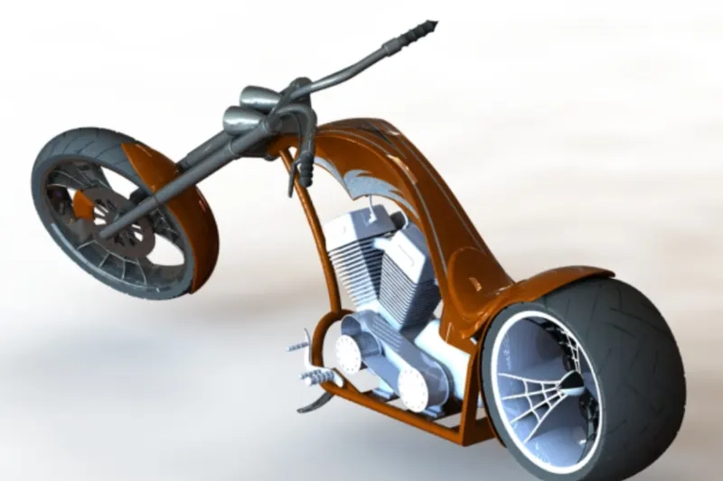
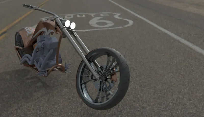
CONCULSION
End of this american chooper i learned a new features an tools assemblesy plans an models etc
learn about light,back ground setting, colours,etc