Radar Mast & Final Assembly of Yacht
DESIGN OF YACHT USING SOLIDWORKS
AIM: The main aim of this project is to learn to model the exact exterior of a yacht by blueprints setup using Solidworks and applying a Photorealistic view by Solidworks visualize software.
OBJECTIVE: The objective of this project is to model the different parts of the yacht and assemble them using Solidworks. For this project, I’m using Solidworks 2020 student edition to build and improve the yacht model.
FEATURES/TOOLS USED TO CREATE YACHT:
I. SKETCH: To begin, create a new part and select your desired template. Once the user interface is visible click the sketch tab of the command manager & select the sketch icon on the left-hand side. We can also search for commands in SOLIDWORKS if we don't know where they are.
II. REVOLVE: After creating a new 2d sketch, create all solid sketch geometry on one side of the axis, choose Revolve Boss/Base from the feature menu select the axis you wish to use for the revolve.
III. LOFT: The loft feature in SolidWorks allows you generate complex geometry in a single feature. It does this by interpolating surfaces between various cross-sections of a model. These cross-sections can be sketches, faces, or edges.
IV. FILLET: Fillet/ Round creates a rounded internal or external face on the part. You can fillet all edges of a face, selected sets of faces, selected edges, or edge loops.
V. CIRCULAR PATTERN: Use the circular pattern to create multiple instances of one or more features that you can space uniformly around the axis.
VI. EXTRUDE BOSS/BASE: An Extrude Boss/Base feature will allow you to take a 2d sketch and add thickness to it in the third dimension.
VII. MIRROR: Pattern/Mirror is used to create an opposite-hand version of an object. You must choose a plane to mirror parts. In most cases, you will have to create your plane to have the mirror done the way you need.
VIII. SKETCH DRIVEN PATTERN: Using sketch points within a sketch you can specify a feature pattern. The sed feature propagates throughout the pattern for holes or other feature instances.
IX. PROJECT CURVE: It is a tool to use to form 3D curves from 2D curves from different planes.
X. SWEEP: A sweep is a tool that creates a solid, a cut, or a surface feature by moving a profile along a path.
XI. EXTRUDE CUT: This is a handy feature to aid in the material removal of a 3D model using 2D sketches.
XII. SPLIT: To cerate multiple parts from an existing part. You can create a separate part file, and form an assembly from the new parts. You can split one or more solid or surface bodies.
XIII. SHELL: It is used to haloes out a part, leaves open the faces you select, and creates thin-walled features on the remaining faces. You can shell a solid part, creating a closed hollow model. You can also shell a model using multiple thicknesses.
XIV. EXTEND SURFACE: You can extend a surface by selecting an edge multiple edges, or a face. Under Edges/Faces to extrude, select one or more edges or faces in the graphics area for selected face edges.
XV. SURFACE KNIT: Use the surface knit tool to combine two or more faces and surfaces into one. Knit surfaces absorb the surface bodies you used to create them. Create a solid body when the knit surfaces form a closed volume or leave as a surface body. Select merge entities to merge faces with the same underlying geometry.
XVI. SURFACE LOFT: To create a lofted surface create a plane for each profile section of the loft. The planes do not need to be parallel. Sketch the section profiles on the planes. Click lofted surface.
XVII. CHAMFER: The chamfer tool creates a beveled feature on selected edges, faces, or vertex.
XVIII. SURFACE TRIM: You can use a surface, plane, or sketch as a trim tool to trim intersecting surfaces.
XIX. SURFACE FILL: The filled surface feature constructs a surface patch with any number of sides, within a boundary defined by existing model edges, sketches, or curves, including composite curves.
XX. DOME: You can create one or more dome features simultaneously on the same model. The parameters in the dome property manager include faces to the dome. Select one or more planar or non-planar faces.
XXI. SPLIT LINE: Tool is used to project an entity onto other surfaces or curved/planar faces. you can also able to split faces on multiple bodies with one command.
XXII. OFFSET: One or more sketch entities selected model edges, or model faces by a specified distance.
XXIII. SURFACE OFFSET: The command gives the user the option to SEE and REMOVE any surfaces that cannot be offset building the remaining geometry.
XXIV. CONVERT ENTITIES: The tool allows users to make a copied projection of a given sketch, face, or set of edges onto the active sketch plane.
XXV. SWEPT BOSS/BASE: The swept boss is one of the useful features which help to sweeps a closed profile through an open or closed path.
XXVI. DELETE SURFACE: Can delete faces from the surface and solid bodies.
XXVII. BOUNDARY SURFACE: This feature lets to create surfaces that can be tangent or curvature continuous in both directions.
LIST OF PARTS IN THE YACHT: To model the perfect yacht’s exterior it’s divided into parts as mentioned below.
1.PROPELLER
2.RADAR
3.HULL
4.GARAGE DOOR
5.FRONT SEAT
6.MIDDLE SEAT
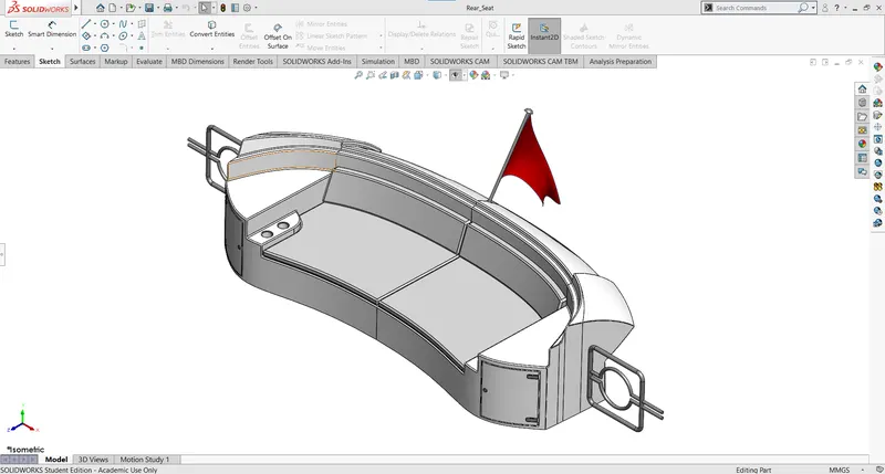
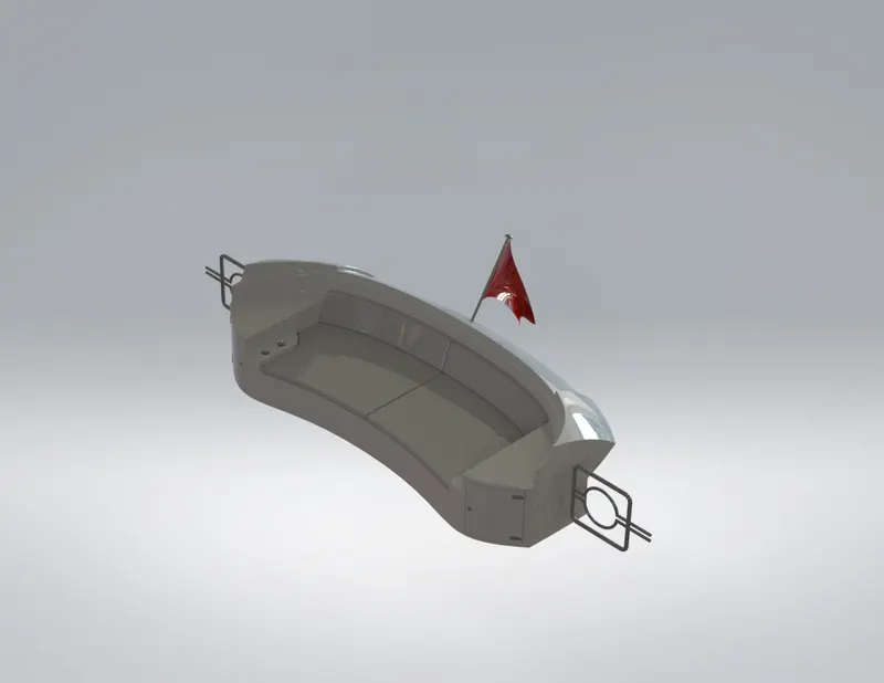
7.REAR SEAT
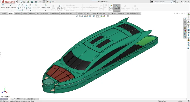
8.SUPERSTRUCTURE
9.RADARMAST
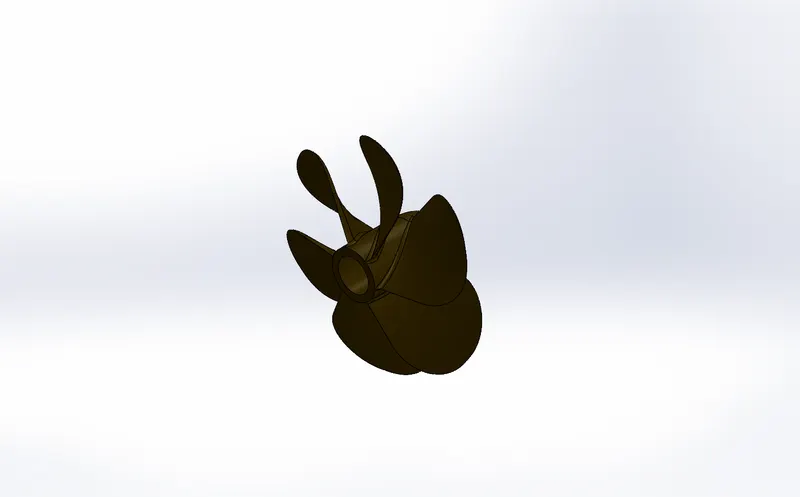
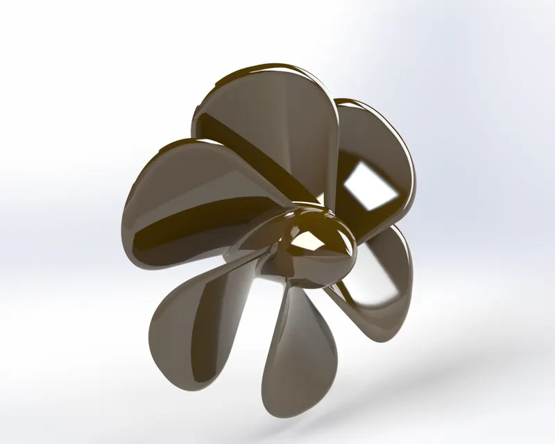
1. PROPELLER: A propeller is a fan mechanism that transmits power by converting rotational motion into thrust. Usually consisting of 3 or more blades.
PROCEDURE & FEATURES:
* Draw 2d sketch
* Revolve
* Cut extrude
* Loft
* Fillet
* Circular pattern
Select plane to draw a 2D sketch with given dimensions, use Bass/Base Revolve tool for revolving. Use loft and Cut extrude for propeller blade fillet the sharp edges, circular pattern the blade with required number and give the appearance as like we want to see.
CAD MODEL VIEW
RENDERED VIEW
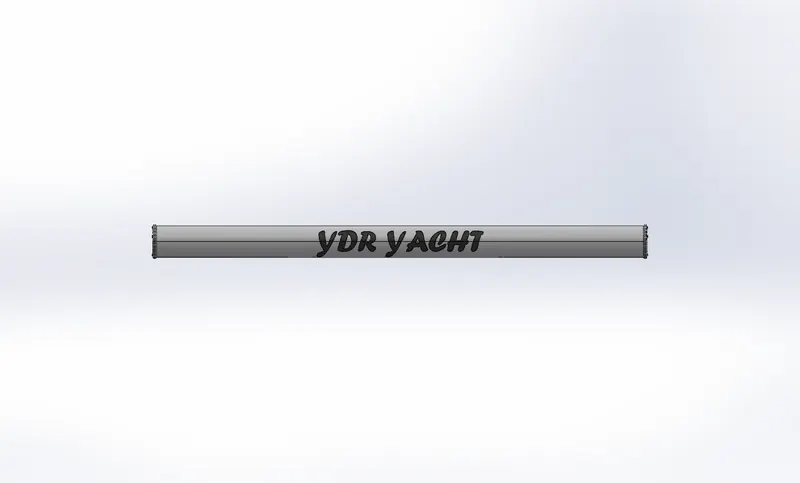
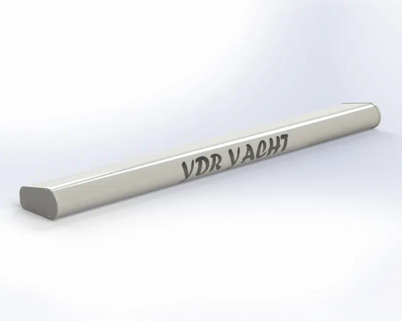
2. RADAR: A mandatory aid to navigation, the radar is used in identifying, tracking(with integrated ARPA), and positioning vessels among other things to adhere t the CLOREGs to safely navigate a ship from one point to another.
PROCEDURE & FEATURES:
* Draw 2d sketch
* Extrude
* Mirror
* Cut extrude
* Fillet
* Sketch driven pattern
Select plane for sketch the 2D model, use extrude and fillet the round edges. Draw pins on the side of the radar, mirror it on the other side and merge solid option. Draw a circle on the top and cut extrude. Name your radar and give the appearance.
CAD MODEL VIEW
RENDERED VIEW
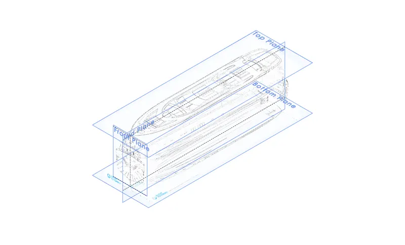
BLUEPRINT SETUP IMAGES:
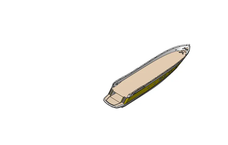
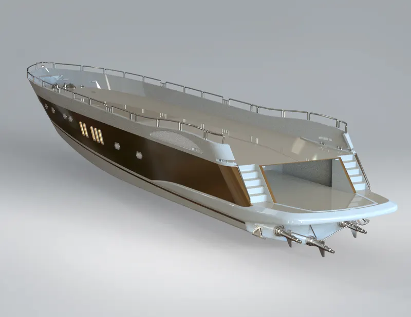
3. HULL: A hull is the watertight body of a ship or boat. The hull may open at the top, or it may be fully or partially covered with a deck. The line where the hull meets the water surface is called the waterline.
PROCEDURE & FEATURES:
* Draw 2d sketch
* Project curve
* Swept curve
* Loft surface
* Extrude surface
* Extend surface
* Surface knit
* Extrude
* Mirror
* Cut extrude
* Fillet
* Pattern
* Split
* Shell
To model the hull, first set up the blueprints planes give names according to the model for sketching convenience. Model the Hull on each side of the blueprints with the help of the features mentioned above. After modeling the Hull give decals to the floor finally give an appearance to your taste.
CAD MODEL VIEW
RENDERED VIEW
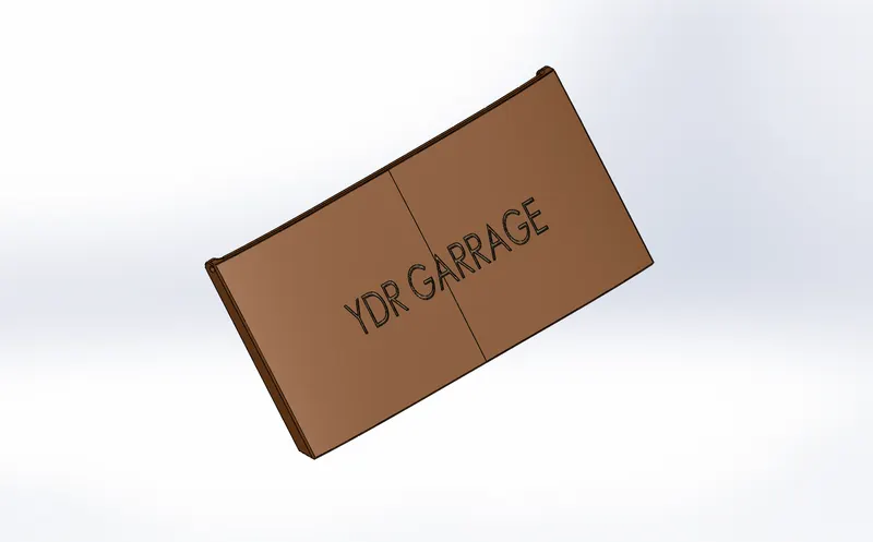
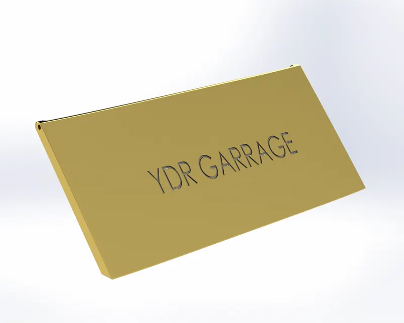
4. GARAGE DOOR: The garage door is used to close the garage part in the hull.
PROCEDURE & FEATURES:
* Shell
* Chamfer
* Fillet
* Extrude cut
* Text
* Mirror
For the garage door first, we have to import open the Stock Hull we saved in the hull model. Draw a 2D sketch on Stock Hull's body to cut extrude the door. Make shell the remaining body with the shell command fillet the sharp edges, mirror it on the other side of the body using a plane as the reference. Text on the garage door what you want to display give an appropriate appearance.
CAD MODEL VIEW
RENDERED VIEW
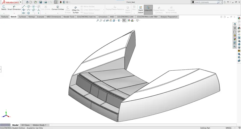
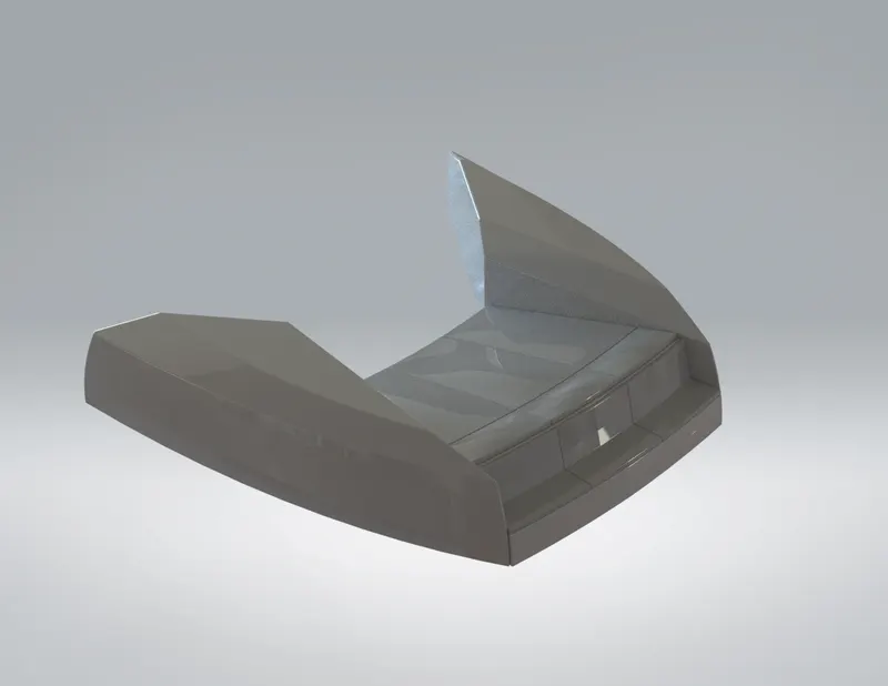
5. FRONT SEAT: The front seat is placed in the front part of the hull.
PROCEDURE & FEATURES:
* Surface sweep
* Surface extend
* Surface trim
* Surface fill
* Surface loft
* Surface knit
* Chamfer
* Fillet
* Revolve
* Cut extrude
* Dome
Open blueprint set up change file name to the Front seat, open part insert hull part open the hull file insert it only selecting surface bodies option. Hide all planes of blueprints except top plane blueprint set up. Using top blueprint set up sketch Front Seat with the features mentioned above, give the appearance.
CAD MODEL VIEW
RENDERED VIEW
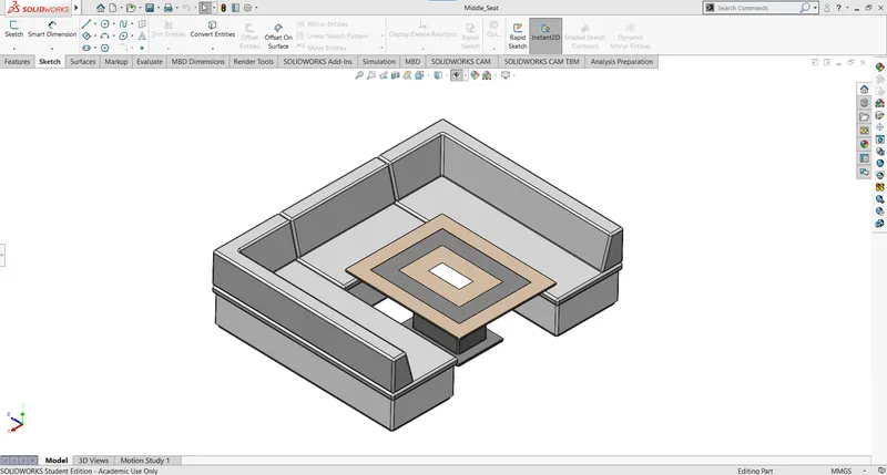
6. MIDDLE SEAT: The middle seat is placed under the superstructure.
PROCEDURE & FEATURES:
* Boss extrude
* Cut extrude
* Fillet
* Chamfer
For the middle seat, modeling follows the same procedure as the front seat to complete the Middle seat.
CAD MODEL VIEW
RENDERED VIEW
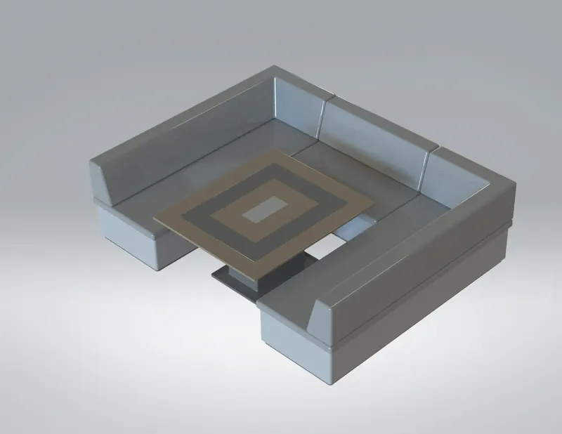
7. REAR SEAT: The rear seat is placed at the back of the hull.
PROCEDURE & FEATURES:
* Fillet
* Chamfer
* Split line
* Cut extrude
* Surface offset
* Surface trim
For the rear seat, modeling follows the same procedure as the Front seat and Middle seat to complete the Rear seat.
CAD MODEL VIEW
RENDERED VIEW
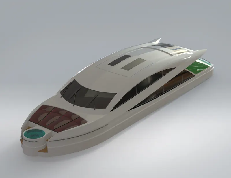
8. SUPERSTRUCTURE: In this yacht, it is the name given to the ship that emerges from the deck.
PROCEDURE & FEATURES:
* Draw 2d sketch
* Project curve
* Surface trim
* Surface fill
* Extend surface
* Surface extrude
* Lofted surface
* Boundary surface
* Delete surface
* Fillet
* Swept surface
* Surface knit
* Boss extrude
* Cut extrude
* Split
* Mirror
For modeling, superstructure open blueprint setup, show top view insert Hull part selecting surface bodies option. Draw 2D, 3D sketches on the blueprints accordingly use the features mentioned above to complete the superstructure of the Yacht. Give an appearance to finish the model.
CAD MODEL VIEW
RENDERED VIEW
9. Radar mast:
PROCEDURE & FEATURES:
* Revolve
* Sketch
* Boss extrude
* Fillet
* Mirror
* Swept boss/base
* Shell
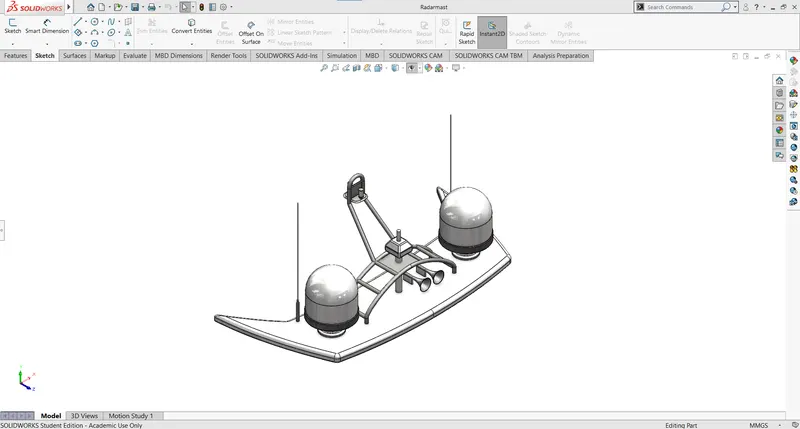
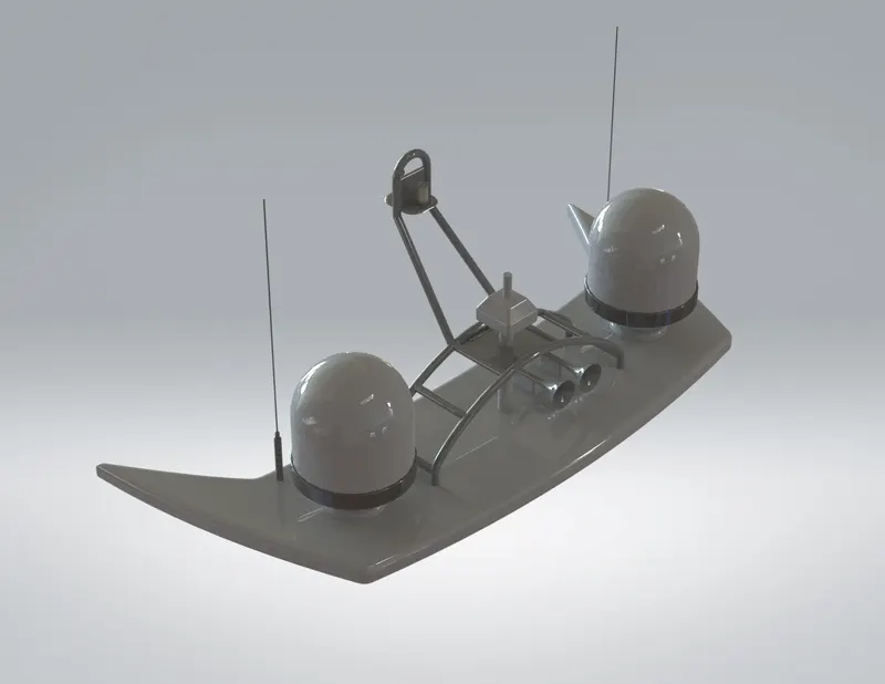
The radar mast is the final part of the Yacht in this model, open blueprint set up file change name to radar mast, insert file part of the superstructure by enabling only surface bodies option. Finish the part as per the instructions using the features mentioned above and give an appropriate appearance to assemble the parts in the assembly environment.
CAD MODEL VIEW
RENDERED VIEW
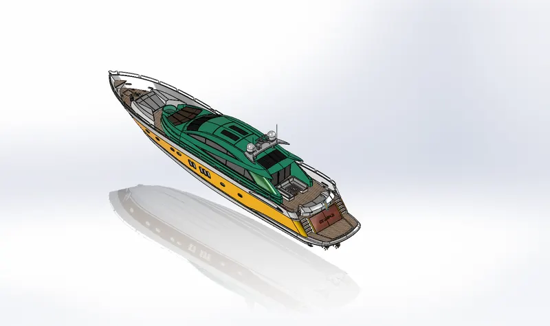
10. Assembly:
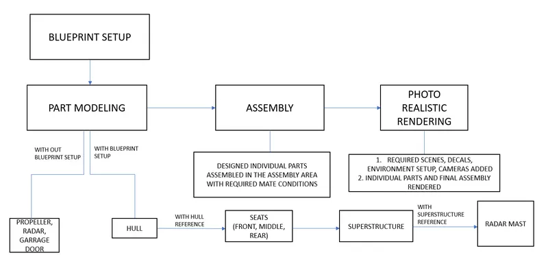
* The modeled parts of the yacht are inserted in this assemble environment.
*The possible mate conditions are given to assemble the yacht.
ASSEMBLY TREE:
CAD MODEL VIEW
RENDERED VIEW
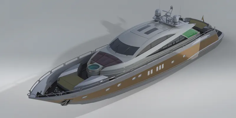
RENDERING:
* The photorealistic rendering of the assembled model is created.
* Camera setup/ Perspective view added in Photo view 360.
* The process of a digital image is created.
RENDER VIEW
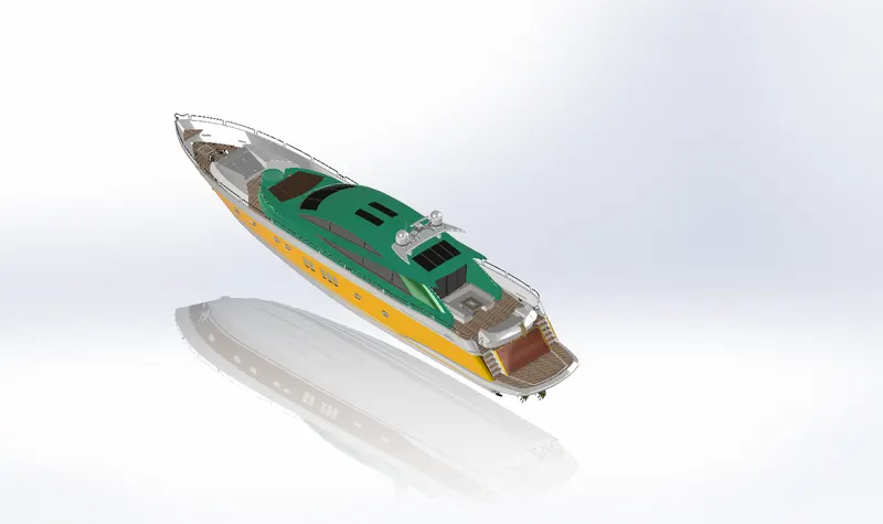
CARTOON VIEW
REAL VIEW GRAPHIS
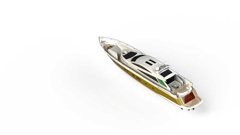
CONCLUSION: At the end of the project, each component is designed individually in part file and assembled into a complete Yacht design. Additional/setup like decals, scenes, camera setup, etc….. given to make it more realistic for final rendering.