Photo Realistic Rendering
DESIGN OF AMERICAN CHOPPER
WITH
PHOTO REALISTIC RENDERING
AIM: To sketch & build every part of the chopper and assembly it using Solidworks and make the chopper more realistic using Photo view360 and Solidworks visualization for final rendering.
OBJECTIVE:
- Implementing Shell Features, Sketch blocks, and Linear& Circular patterns.
- Gaining information of Composite curves and make pierce feature in Solid Works.
- Creation of Projected curves and utility, Revolve cut features.
- Assembling features, mates and tangent mates relations.
- Photo view360 and camera setup and utilities.
- Environment setup and Solid Visualization of American chopper.
- Gain detailed knowledge of Solid and Surface modeling in Solidworks.
AGENDA FOR ACTION TO DESIGN AMERICAN CHOPPER:
|
Part designing |
Assembly |
Photo view360 (Decals, Camera setup, Scenes, Lights) |
Solid Visualization |
LIST OF PARTS DESIGNED:
American chopper consists of 13parts, they are as follow
- Transmission Belt
- Kick Stand
- Transmission Chain
- Rear Fender
- Rear Wheel
- Pedal
- Front Fender
- Front Wheel
- Oil Tank
- Front Fork
- Chassis
- Engine
- Gas Tank
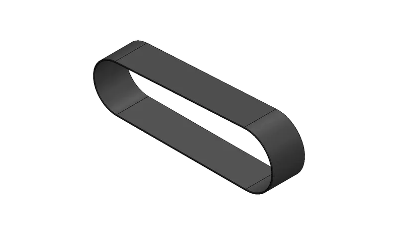
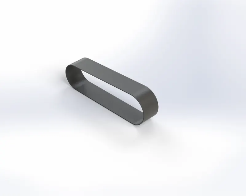
1.Transmission Belt:
Belts are mechanical elements used for power transmission without phase shift. They are loops of flexible materials use to mechanically connect several shafts most often parallel.
Procedure & Features:
- Draw a 2d sketch
- Draw two circles, two straight lines to connect them
- Trim lines
- Thin Extrude
- Add Fillets
Materials& Appearance: Mate Rubber.
- CAD MODEL PREVIEW
- RENDER PREVIEW
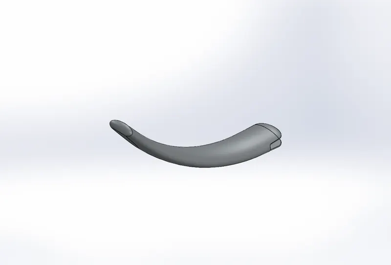
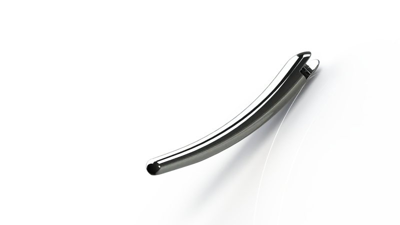
2. Kick Stand:
Kickstand usually a piece of metal that flips down from the frame and makes contact with the ground. That allows a bicycle or motorcycle to be kept upright without leaning against another object or the aid of a person.
Procedure & Features:
- Draw a 2d sketch with pierce relation
- Extrude
- Extrude cut
- Loft
- Dome
- Fillet
Material & Appearance: Chrome Steel.
- CAD MODEL PREVIEW
- RENDER PREVIEW
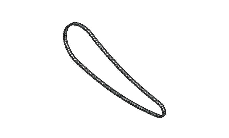
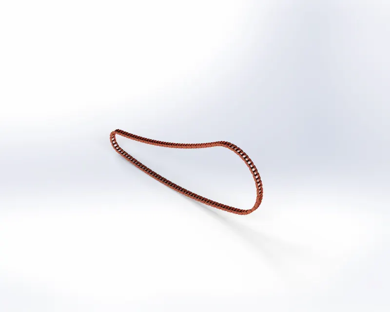
3. Transmission Chain:
It consists of a series of short cylindrical rollers held together by side links. It is driven by a toothed wheel called a sprocket. It is a simple reliable and efficient means of power transmission.
Procedure & Features:
- Draw a 2d sketch and use blocks to create a chain
- Extrude
- Mirror
- Fillet
- Curve driven pattern
Material & Appearance: Chrome Steel with Copper coating.
- CAD MODEL PREVIEW
- RENDER PREVIEW
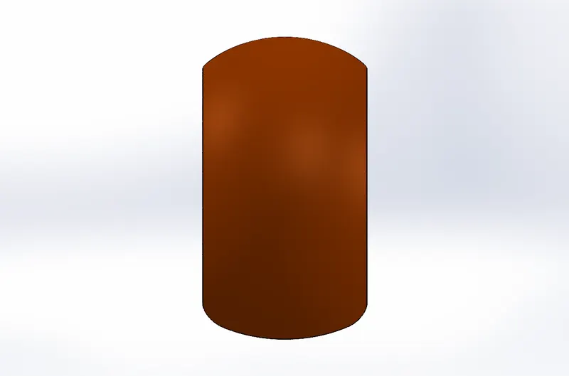
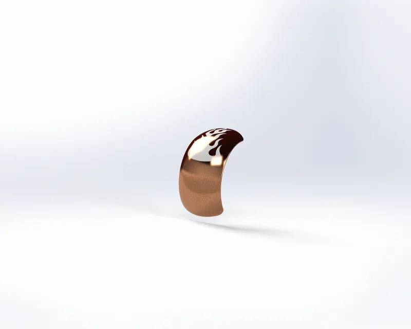
4. Rear Fender:
Fender is part of an automobile, motorcycle, or other vehicle body that frames a wheel well. Its primary purpose is to prevent sand, mud, rocks, liquids, and other roads spray from being thrown into the air by the rotating tire.
Procedure & Features:
- Draw a 2d sketch
- Revolved surface
- Surface trim
- Thicken
- Extrude cut
- Fillet
- Shell
- Insert a split line
Material & Appearance: Painted Siena.
- CAD MODEL PREVIEW
- RENDER PREVIEW
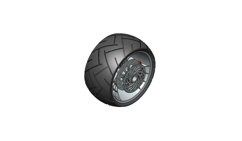
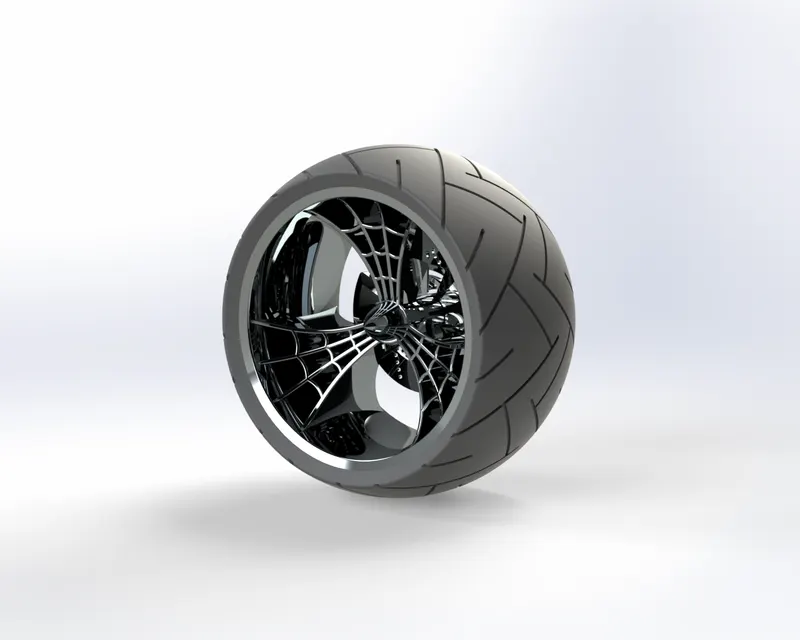
5. Rear wheel:
The wheels of a vehicle are the circular objects which are fixed underneath it and which enable it to move along the ground. It consists of Rim, Caliper, Rotor, Tire & Sprocket.
Procedure & Features:
- Draw a 2d sketch
- Extrude
- Extrude cut
- Thin extrude
- Revolve
- Revolved cut
- Fillet
- Chamfer
- Linear pattern
- Mirror
- Circular pattern
Solid bodies:
Rim, Rotor, Caliper, Sprocket, Tire.
Material & Appearance:
Rim (chrome steel)
Rotor (carbon steel)
Caliper (painted Siena)
Sprocket (chrome steel)
Tire (Mate rubber)
- CAD MODEL PREVIEW
- RENDER PREVIEW
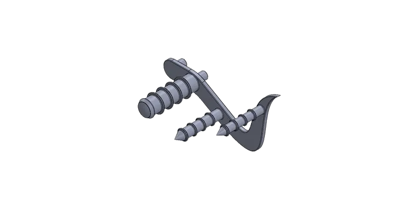
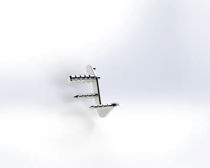
6.Pedal:
The part is externally attached to the chassis which is used for foot resting and gear changing.
Procedure & Features:
- Draw 2d sketch
- Extrude
- Revolve
- Dome
- Linear pattern
- Fillet
- Chamfer
Material & Appearance: Chrome steel.
- CAD MODEL PREVIEW
- RENDER PREVIEW
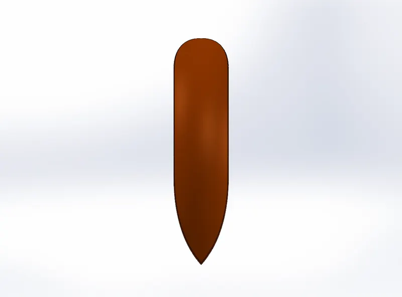
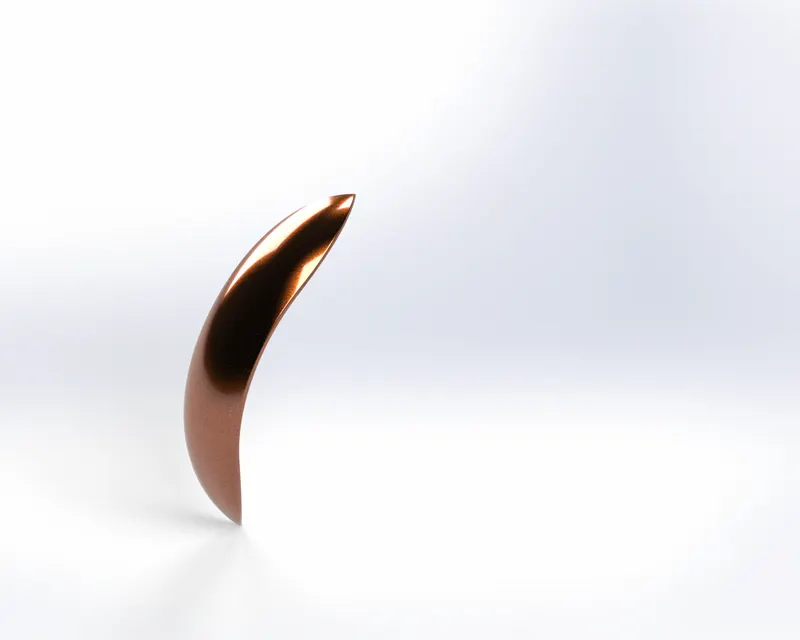
7. Front fender:
Fender is part of an automobile, motorcycle, or other vehicle body that frames a wheel well. Its primary purpose is to prevent sand, mud, rocks, liquids, and other roads spray from being thrown into the air by the rotating tire.
Procedure & Features:
- Draw 2d sketch
- Revolved surface
- Surface trim
- Thicken
- Extrude cut
- Fillet
Material & Appearance: Painted Siena.
- CAD MODEL PREVIEW
- RENDER PREVIEW
8. Front Wheel:
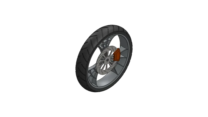
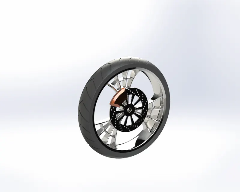
A circular frame of hard material that may be solid, partly solid, or spoked and that is capable of turning on an axle.
Solid bodies:
Rim, Rotor, Caliper, Sprocket, Tire.
Rim (chrome steel)
Rotor (carbon steel)
Caliper (painted Siena)
Sprocket (chrome steel)
Tire (Matte rubber)
Procedure & Features:
- Draw 2d sketch
- Extrude
- Extrude cut
- Thin extrude
- Revolve
- Revolve cut
- Fillet
- Chamfer
- Liner pattern
- Mirror
- Circular pattern
Material & Appearance: Chrome steel, Mate rubber.
- CAD MODEL PREVIEW
- RENDER PREVIEW
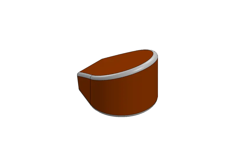
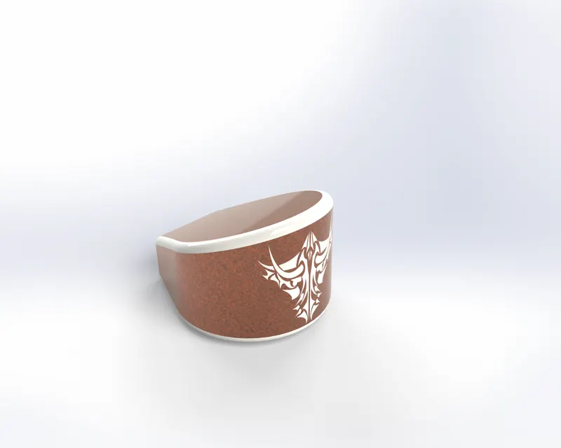
9. Oil tank:
Oil tank or Oil sump is a component of the engine lubrication system in motor vehicles, It is also known as the oil tray. The oil tank contains the engine oil required for lubrication. The oil is extracted from it by an oil pump and conveyed into the engine block’s oil ducts via an oil filter. The oil then flows back into the oil sump from the lubrication points.
Procedure & Features:
- Draw 2d sketch
- Surface extrude
- Fillet
- Surface trim
- Surface knit
- Shell
- Extrude
Appearance: Painted Siena, White paint for decals.
- CAD MODEL PREVIEW
- RENDER PREVIEW
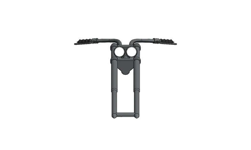
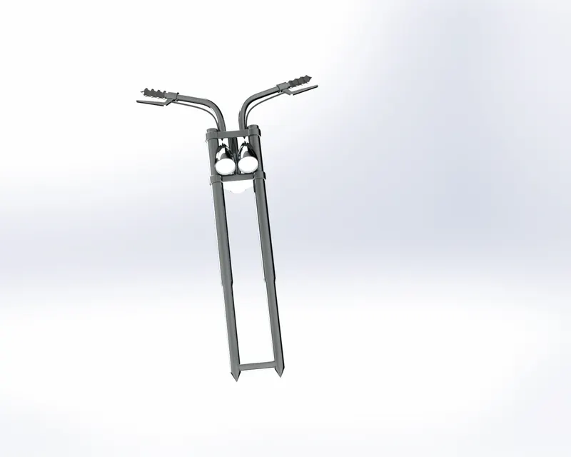
10. Front Fork: The front suspension or fork takes a large majority of the raider’s weight, as mountain biking sees the rider often riding with more weight over the front of the bike the front l is attached to the fork lower while the stanchions are attached to the head tube of a bike frame via the fork steerer.
Procedure & Features:
- Draw a 2d sketch
- Extrude
- Revolve
- Fillet
- Sweep
- Shell
- Mirror
- Dome
- Linear pattern
- Projected curve
Appearance: Chrome steel
- CAD MODEL PREVIEW
- RENDER PREVIEW
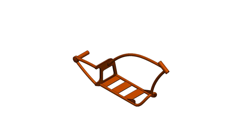
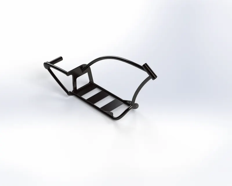
11. Chassis: Much like a human spine and the supporting skeleton a motorcycle chassis holds everything together from the engine, suspension, wheels, fuel tank, handlebars, seat, airbox, etc…
Procedure & Features:
- Draw a 2d sketch
- Extrude
- Extrude cut
- Thin extrude
- Revolve
- Revolve cut
- Mirror
- Sweep
- Dome
- Fillet
- Chamfer
- Projected curve
Appearance: Grease Gray
- CAD MODEL PREVIEW
- RENDER PREVIEW
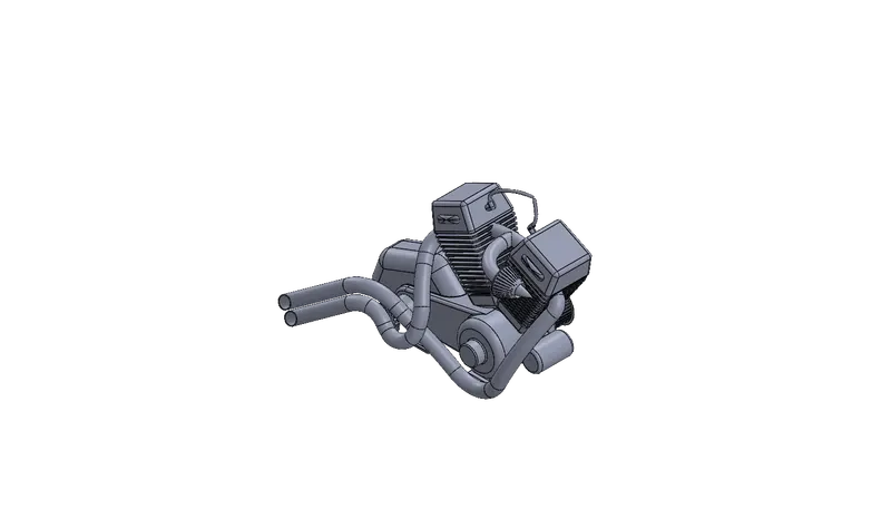
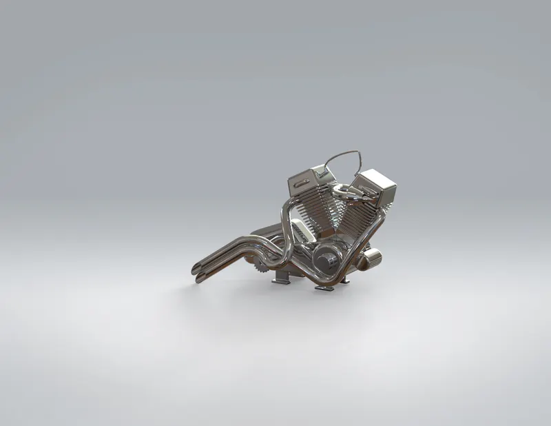
12. Engine: It is a machine for converting thermal energy into mechanical energy or power to produce force and motion.
Procedure & Features:
- Draw a2d sketch
- Extrude
- Extrude cut
- Thin extrude
- Chamfer
- Projected curve
- Linear pattern
- Circular pattern
- Fillet
- Mirror
- Dome
- Sweep
Appearance: Chrome steel.
- CAD MODEL PREVIEW
- RENDER PREVIEW
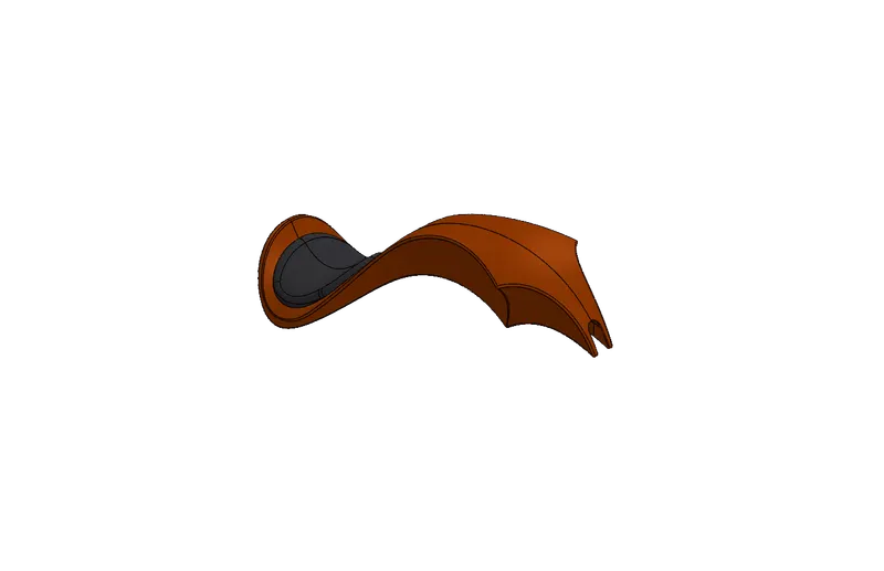
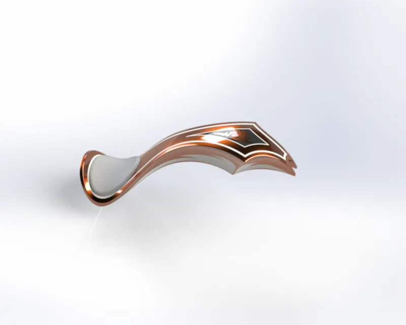
13. Gas tank: A gas tank or fuel tank is a safe container for flammable fluids. Through which fuel is released into an engine.
Procedure & Features:
- Draw a 2d sketch
- Surface swept
- Spit line
- Surface loft
- Mirror surface
- Surface cut
- Swept
Appearance: Painted Siena, Seat ( Grey Fabric)
- CAD MODEL PREVIEW
- RENDER PREVIEW
Assembly: Import the designed parts into solid works assembly and give relations to each other using mates and other relations.
Photo view 360: In this, we can apply Decals, Camera setup for rendering, Scenes, Lights.
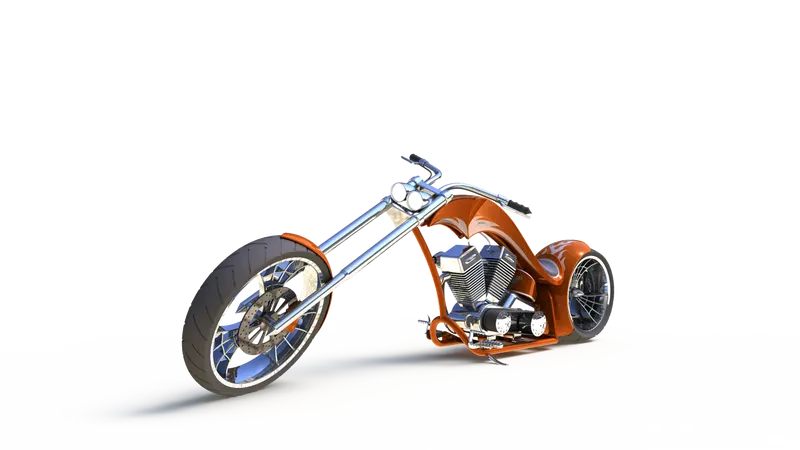
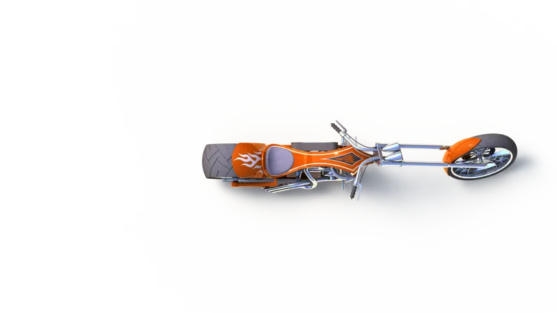
These are some photos of American Chopper Photo View 360 with different views and camera setup along with decals.
Camera setup view
Top view
Cartoon view
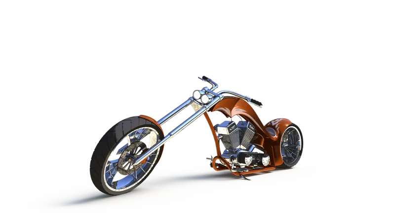
Side view
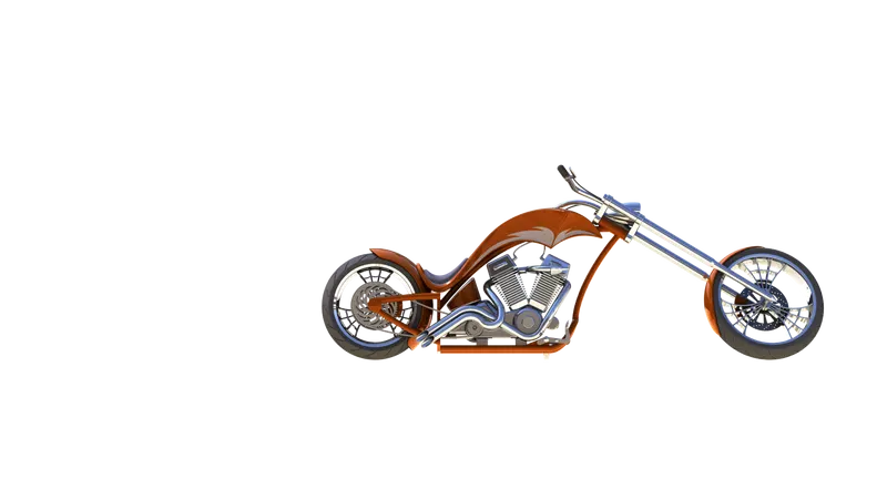
Photo view 360

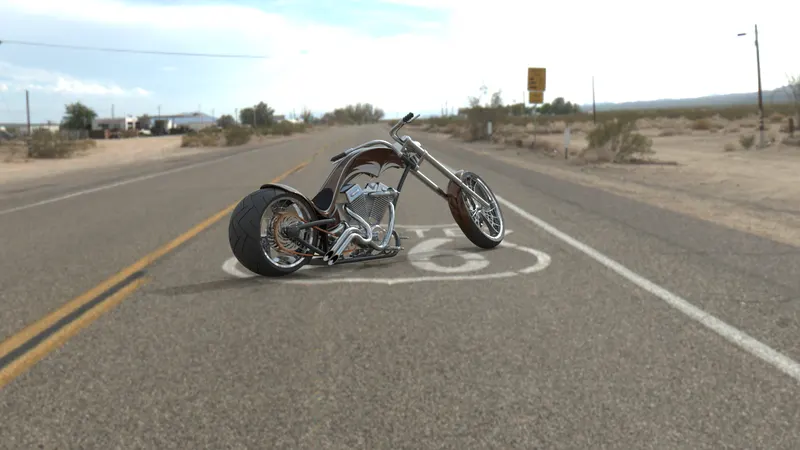
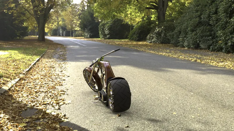
Solid works visualization: Import the assembly Chopper file into solid works visualization and add scenes, lights, appearance as we like and perform render for a realistic experience.
Route-66 rendered view of an American chopper
Dry road rendered view of American chopper
Conclusion: At the end of the project, each component is designed individually in part files and assembled into a complete chopper design. Additional Appearance/ setup like Decals, scenes, Cameras, Lights, etc… given to make it more realistic decent backgrounds Scenes were added to the chopper design for final rendering.