Radar Mast & Final Assembly of Yacht
Tejas_Joshi_Radar_Mast
_______REPORT________________________________________________________________________________________________________
Aim :
To design model and render the yacht.
Objective :
- Understanding user interference in solidworks.
- Draw the sketches with fully defined and Understanding and implementing shell feature sketch blocks and Linear pattern in Solidworks
- Application of relations to the entities.
- Design all parts of the yacht with the reference of planes and saving parts in separate part file, for final assembly.
- Understanding the utility of solidwork tools like Extrude, Extrude cut, Pattering, Revolving, Revolve cut, Trimming, Extend, projected curves, Composite curves, Make pierce features etc.
- Understanding the full pledged surface feature and its uses to model the yacht.
- Assembling all parts using assembly interference.
- Understanding of mating systems.
- Understanding of photo realistic rendering.
Introduction:
A yacht is any sail or power vessel used for pleasure, cruising or racing.The word often connotes luxury however, luxury is not a quality necessary to meet the definition, nor is it always desirable.Many racing yachts are stripped out vessels with a minimum of accommodations to lower weight . The term sailboat or sail yacht is used to America to differentiate from a powerboat or power yacht as a December 2018 there were about 6500 yachts over 24 million on the market.
It is a watercraft used for pleasure or sports.The term originates from the dutch word yacht which means hunt, and originally referenced light, fast sailing vessels that the dutch republic navy used to pursue pirates and other transgressors around and into the shallow waters of the lower countries.The yacht was popularized by Charles ll of England as a pleasure or recreation vessel following his restoration in 1660.
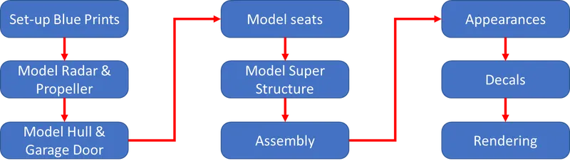
Design Methodology :
Features Description :
Sketch : A sketch is almost always the first step in designing a new part. This feature in solidworks used to draw 2D geometry with reference to plane.
Boss Extrude : Extrude is a feature that is used to convert the 2D sketch into the 3D model.
Fillet : Fillet/Round creates a rounded internal or external face on the part. You can fillet all edges of a face, selected sets of faces, selected edges, or edge loops.
Offset : Offset entities takes a copy of your existing geometry and copies it at an offset. Instead of recreating geometry, you can use this to quickly sketch based on model geometry. Offset entities is a great tool for enlarging or shrinking your sketch geometry.
Chamfer : Machinists use chamfers to "ease" otherwise sharp edges, both for safety and to prevent damage to the edges. A "chamfer" may sometimes be regarded as a type of "bevel", and the terms are often used interchangeably.
Extrude cut : Extrude cut is a feature which helps to remove material from the 3D model.It is just opposite to the Boss extrude feature.
Loft : The loft feature is an important tool for modeling in SolidWorks. The loft feature creates a shape by making transitions between multiple profiles and guide curves.This tool is very valuable for modeling complex surfaces. You can do some really cool stuff when you use this feature properly.
Shell : The shell tool hollows out a part, leaves open the faces you select, and creates thin-walled features on the remaining faces. If you do not select any face on the model, you can shell a solid part, creating a closed, hollow model. You can also shell a model using multiple thicknesses.
Revolve : Create a sketch that contains one or more profiles and a centerline, line, or edge to use as the axis around which the feature revolves.
Dome : Dome is a rounded vault forming the outside face or body or structure with a circular base.
Combine : Combine function allows you to add two bodies together, and keep the area that is common to them. To use this feature, we will select the common button,and then under Bodies to Combine, select the two bodies.
Circular Pattern : Circular patterns to create multiple instances of one or more features that you can space uniformly around an axis.
Linear Pattern : Linear patterns to create multiple instances of one or more features that you can space uniformly along one or two linear paths.
Dynamic Mirror : Dynamic Mirror tool used to mirror the selected line,surface or face to the selected plane or line.
Projected curve : The projected curve is used to project the selected sketched curve onto a face or sketch.
Composite curve : The composite curve is used to combine the selected curve,edge and sketch into a single curve.
Trim : The trim command is used to remove or erase the excess line, edges of intersecting line on a 2D sketch.
Split Entities : This is used to split a line to two or more paths.
Split Line : This feature is used to divide parts into multiple parts into multiple bodies . You can use the split line feature to save the new bodies when you split the part or use the Save bodies to save them after the split is complete .
Convert Entities : Converts selected model edges or sketch entities into sketch segments, loft this is a feature which creates a feature by making transitions between profiles. A loft can be a base, boss, cut or surface . we can create a loft using two or more profiles. For a solid loft, the first and last profiles must be model faces or faces created by split lines, planar profiles,or surfaces.
Loft surface : These are surfaces generated by multiple 3D curves or existing edges creating a smooth tangent between the selected curves.
Surface Trim : It is used to cut away material from a surface, and provides two modes that is standard and mutual.
Extend surface : It is used to extend the surface which is already created .there are different options available on the extended surface . we can extend the surface as a same surface or we can extend the surface tangent to the surface.
Surface Knit : It is used to knit the two free edges or open edges of the surfaces together .Also it reduces the gap between the two edges of the surface .
Sweep Surface : This is surfaces that are generated from a section curve positioned along a path.
Filled Surface : This surface feature constructs a surface patch with any number of sides , within a boundary defined edges , sketches or curves, including composite curves by existing model.
Ruled surface : It is used to obtain the extruded surface perpendicular to the plane and can be titled in certain angle .
Roll Back : Rollback is yet another powerful tool that allows going back to any phase of design in case if we need to edit or add some features later. We can use roll-up bar while removing errors too. This reduces the rebuild time and avoids further errors in the children features .
All this are tools used to model the parts
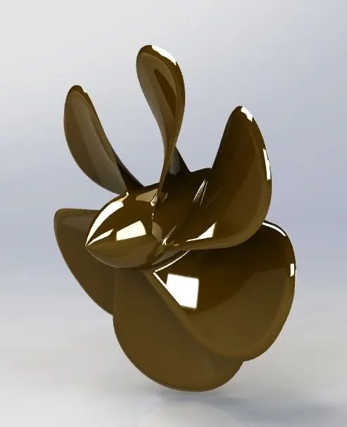
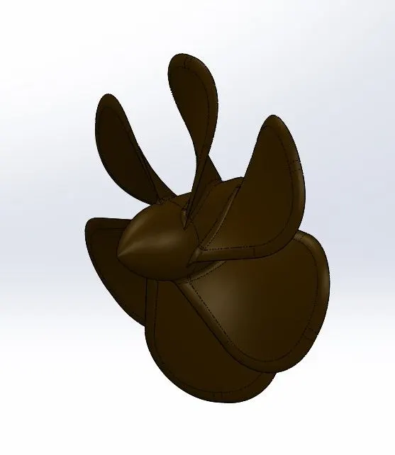
1. Propeller
The propeller provides the thrust for the acceleration of the yacht. It is primarily mounted at the end of the yacht and with the support of a shaft, is connected directly to the engine.
Tool and Features used:
- Sketch
- Line
- Circle
- Loft
- Rectangle
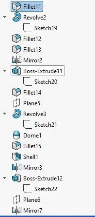
- Revolve
- Cirular Pattern
- Fillet
- Extrude cut
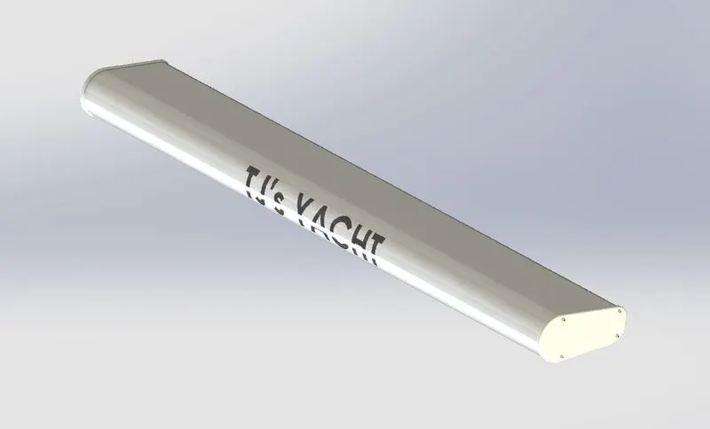
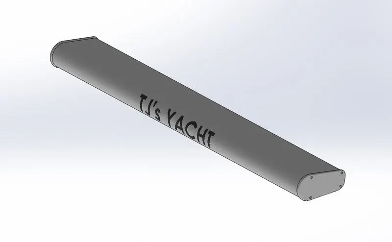
2. RADAR
It is a device which is used to communicate while the yacht is sailing. It is used for transmitting signals and receiving them.
Tools and features used:
- Sketch
- Extrude
- Fillet
- Line
- Polygon
- Circle
- Text
- Mirror
3. HULL
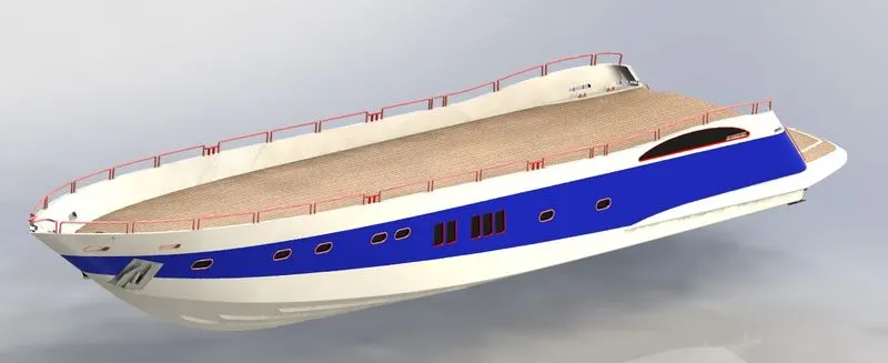
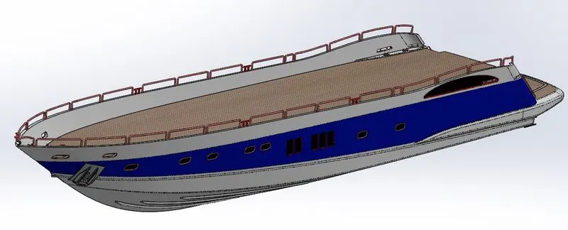
It is the yacht's main body. Supporting all the other objects should be rigid.
Tools and Features used:
- Sketch
- Line
- Circle
- Projected Curves
- Linear Pattern
- Mirror
- Surface Extrude
- Surface Loft
- Extrude Cut
- Fillet
- Chamfer
- Sweep Surface
- KnitSurfae
- Trim
- Offset
- 3D Sketch
- Plane
- Shell
- Helix
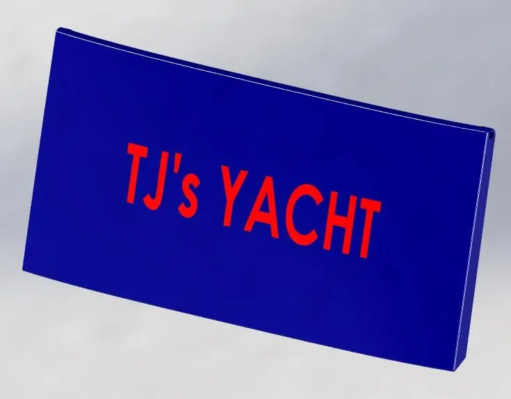
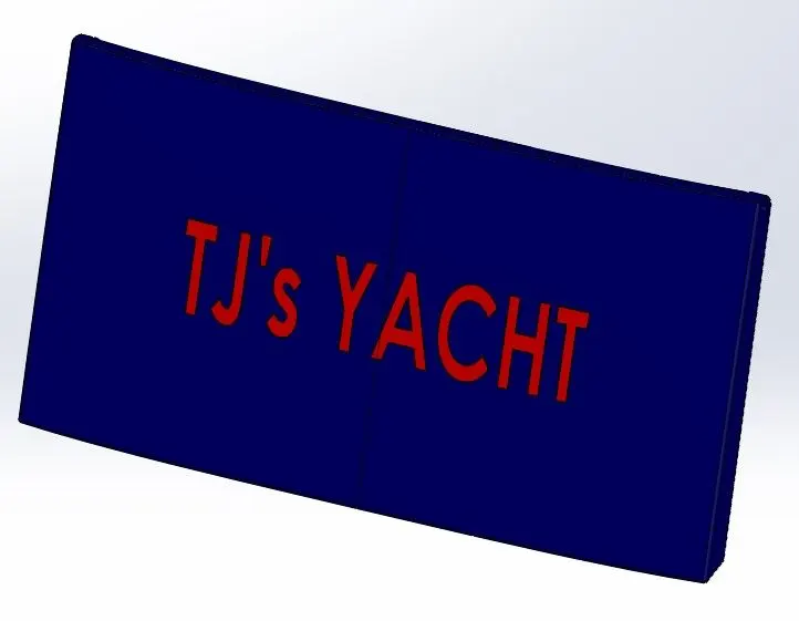
4. GARAGE DOOR
It is the door to the yacht's storage space.
Tools and features used:
- Extrude cut
- Mirror
- Text
- Fillet
- Shell
- Plane
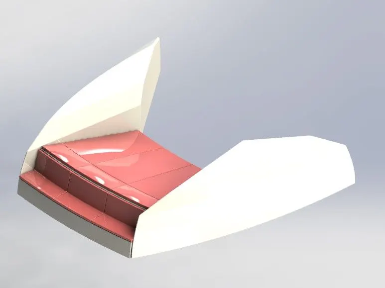
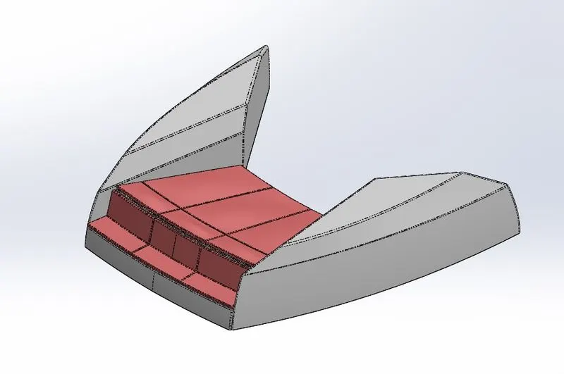
5. FRONT SEAT
For the comfort of the passengers, it is positioned at the front end of the yacht.
Tools and features used:
- Plane
- Sweep Surface
- Loft Surface
- Trim
- Extrude Cut
- Revolve
- Surface Knit
- Surface Fill
- Dome
- Mirror
- Fillet
- Chamfer
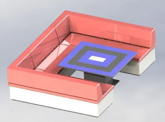
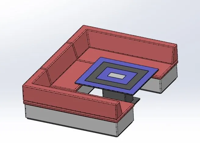
6. MIDDLE SEAT
It is at the middle of the yacht for passengers luxury and comfort.
Tools and features used:
- Extrude Bose
- Chamfer
- Fillet
- Mirror
- Line
- Rectangle
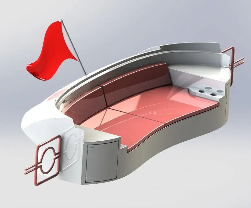
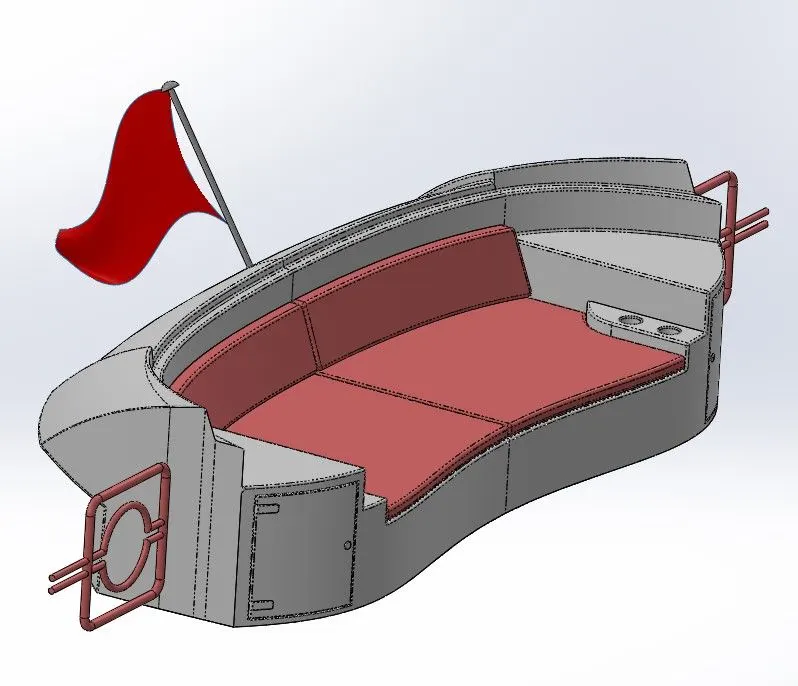
7. REAR SEAT
For passenger comfort, it is located on the rear side of the yacht.
Tools and features used:
- Surface loft
- Surface extrude
- Surface Offset
- Surface trim
- Sweep
- Ruled Surface
- Surface Extend
- Surface Knit
- Surface Extend
- Extrude Bose
- Chamfer
- Extrude Cut
- Mirror
- Plane
- Fillet
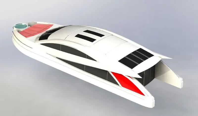
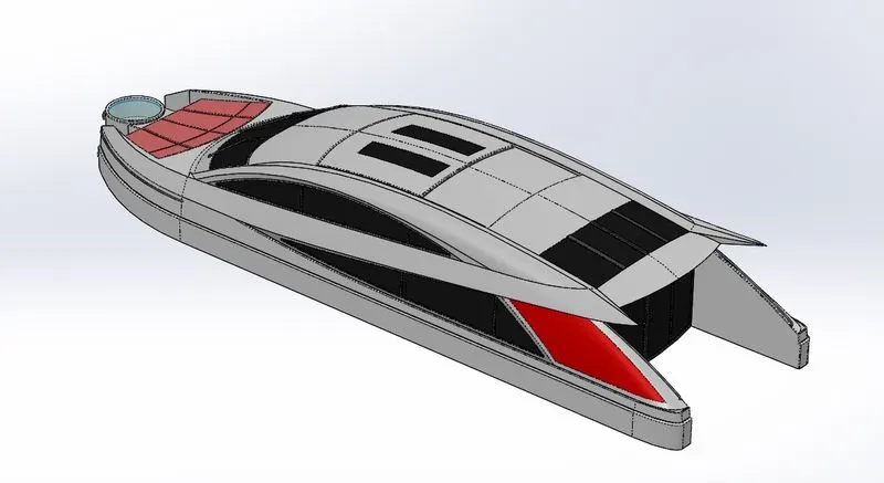
8. SUPERSTRUCTURE
It is the structure designed on the hull. It is the largest compartment for goods and passengers.
Tools and Features used:
- Line
- Spline
- Circle
- Extrude cut
- Projected curves
- Offset
- Surface Fill
- Surface Extrude
- Surface Sweep
- Dome
- Surface Trim
- Extend Surface
- Surface Knit
- Plane
- Ruled Surface
- Split Entities
- Split Lines
- Delete Faces
- Fillet
- Chamfer
- Mirror
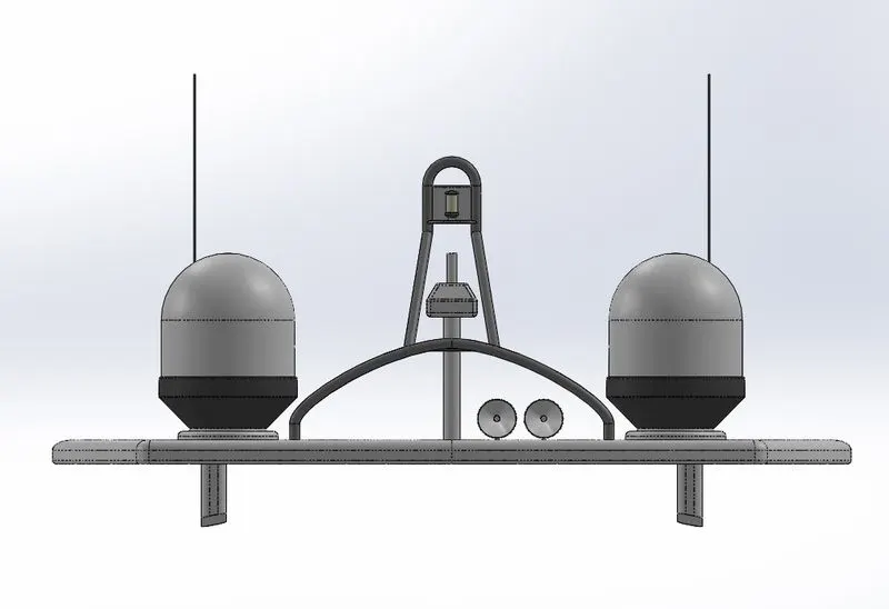
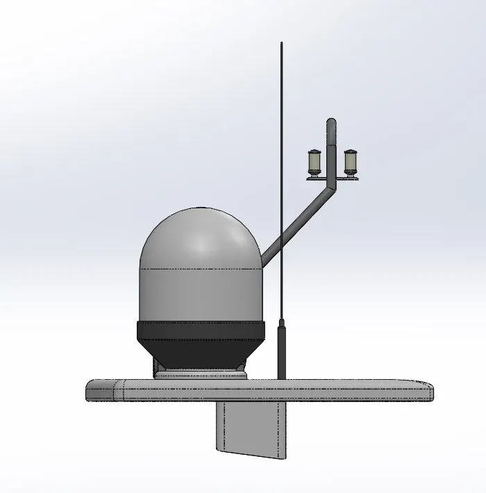
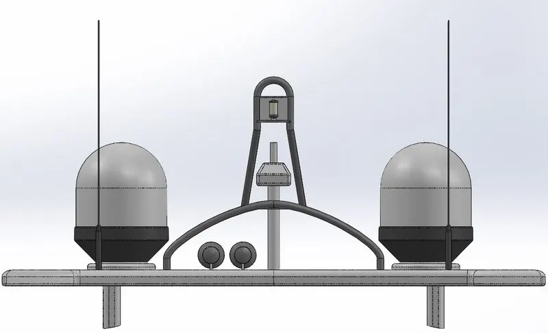
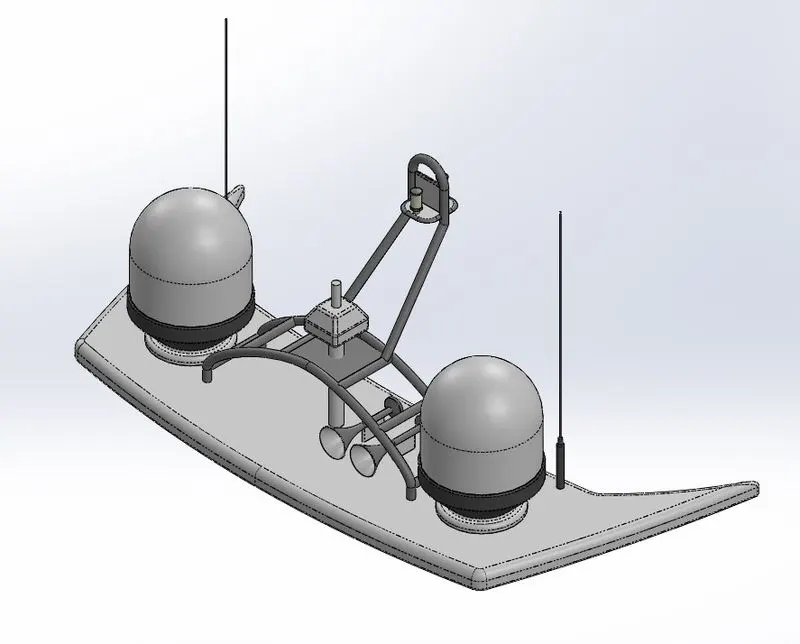
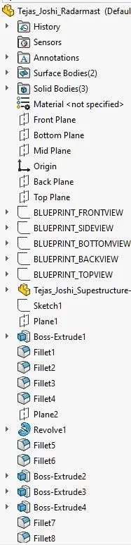
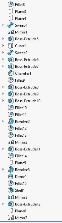
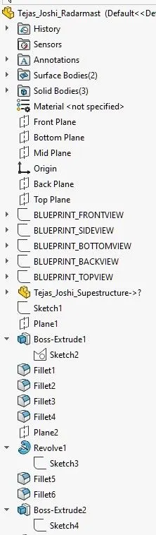
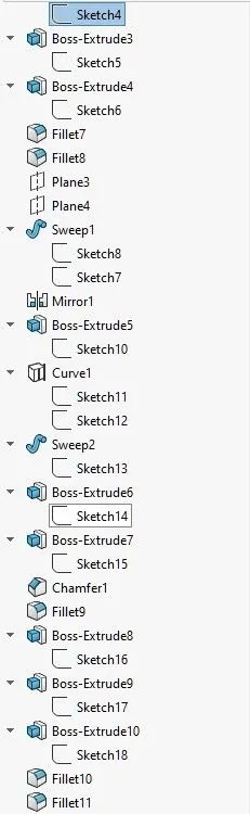
9. RADAR MAST
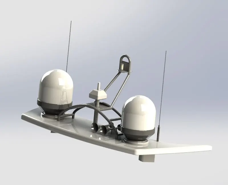
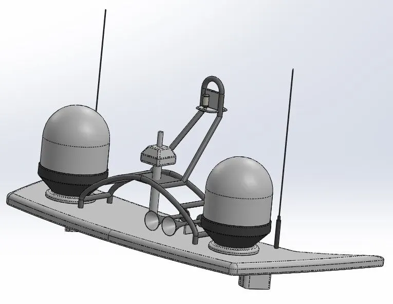
It is the structure which supports the radar.
Tools and the features used:
- Spline
- Extrude Bose
- Revolve
- Circle
- Mirror
- Line
- Fillet
- Chamfer
- Shell
- Projected curve
______ASSEMBLY OF SUNSEEKER PREDATOR YACHT______
MAIN ASSEMBLY :
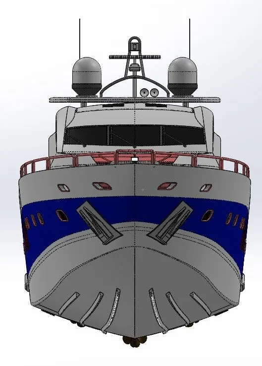
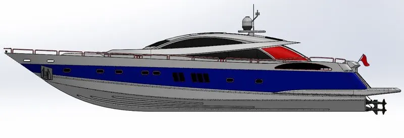
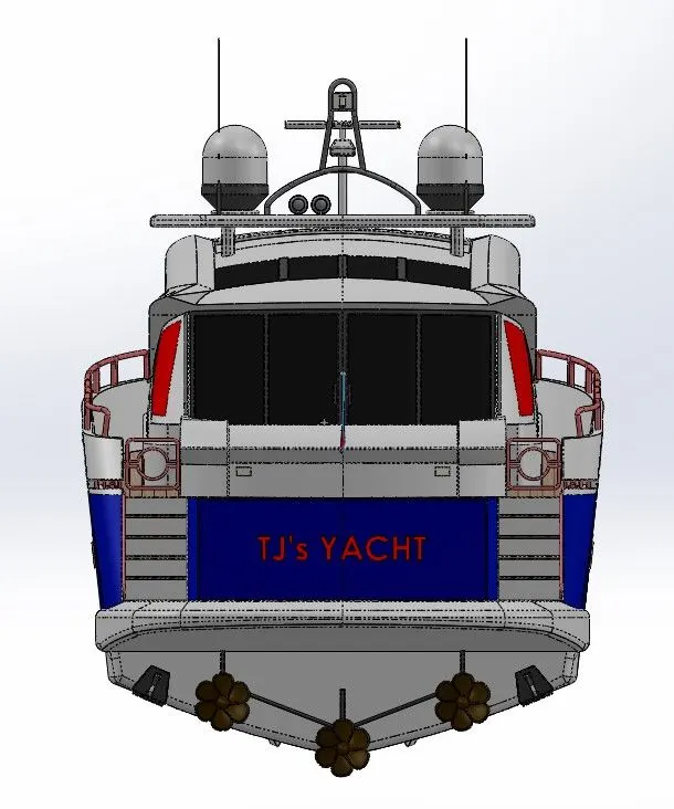
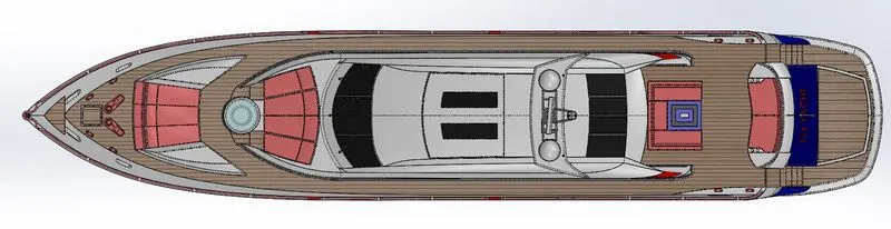
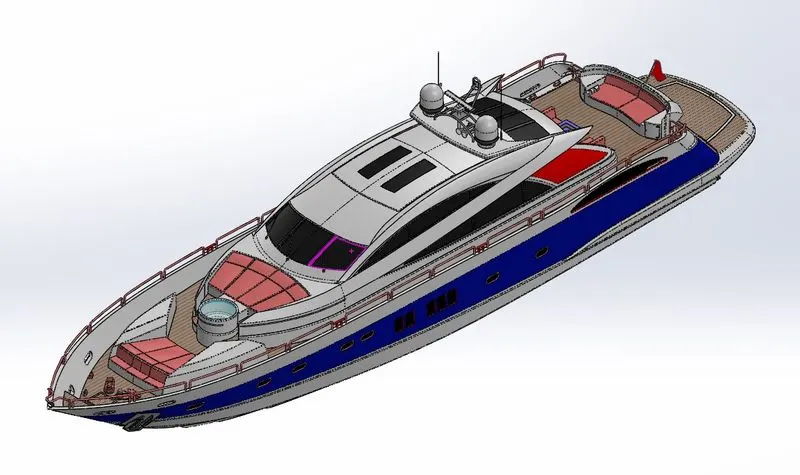
The hull part is initially inserted into the assembly using the insert parts option. After that, the part is placed into the assembly environment and is fixed by clicking OK. Then the other parts of the yacht are then placed into the assembly and the possible conditions are given for mate.
FEATURES USED IN ASSEMBLY :
- Mates
- Insert part
MATES
Mates establish geometric relationships between components of the assembly. We define the permissible directions of linear or rotational motion of the components as we add mates. Within their degrees of freedom, we can transfer a component, envisioning the behaviour of the assembly.
INSERT PARTS
In this feature, the other components that need to be mated with the prime fixed component can be added.
RENDERING
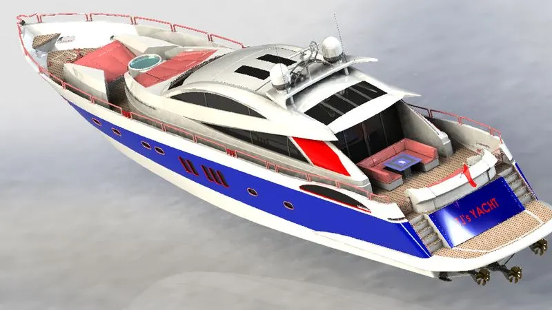
- Rendering is the method by which the photorealistic model creates realistic images of the environment.
Photo view 360

CONCLUSION
- The parts of the Sunseeker Predator Yacht are modeled.
- The parts are inserted into the assembly environment and assembled into an Sunseeker Predator Yacht.
- With the use of Photo-view 360, the photo-realistic image was rendered.