Radar Mast & Final Assembly of Yacht
PLEASE CHECK MS WORD DOC.
Title
- To create Yacht using SolidWorks and rendering Yacht using photoview360
Aim and Objective
- To create different parts of Yacht using 2D sketch.
- Assembling different parts using 3D parts.
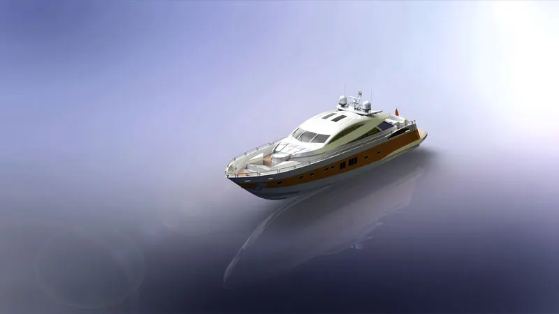
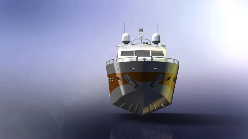
- To create Photorealistic model of Yacht usingphtoview360.
Introduction
The Yacht consists of following parts
- Hull
- Superstructure
- Propeller
- Garage Door
- Radar
- Radar Mast
- Front Seat
- Middle Seat
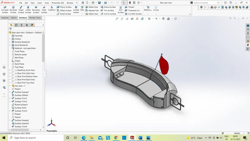
- Rear Seat
Design Methodology
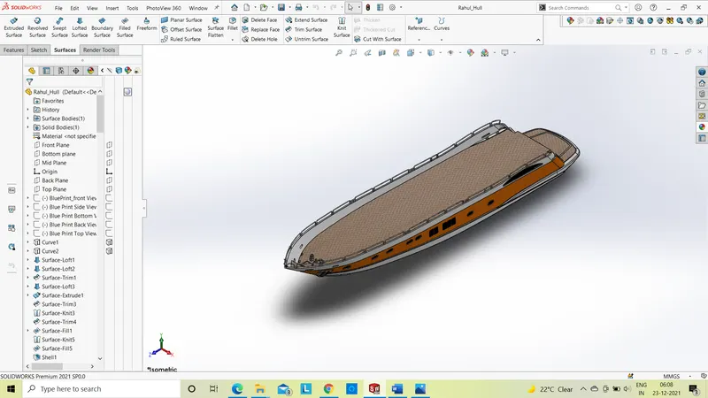
Hull
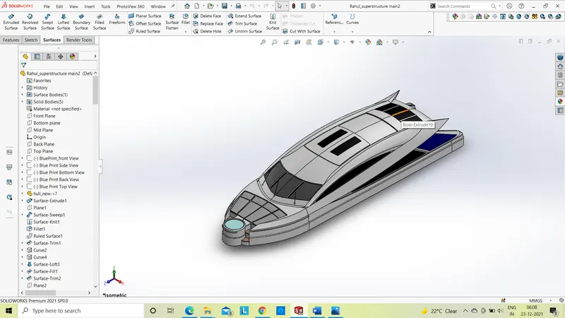
 Superstructure
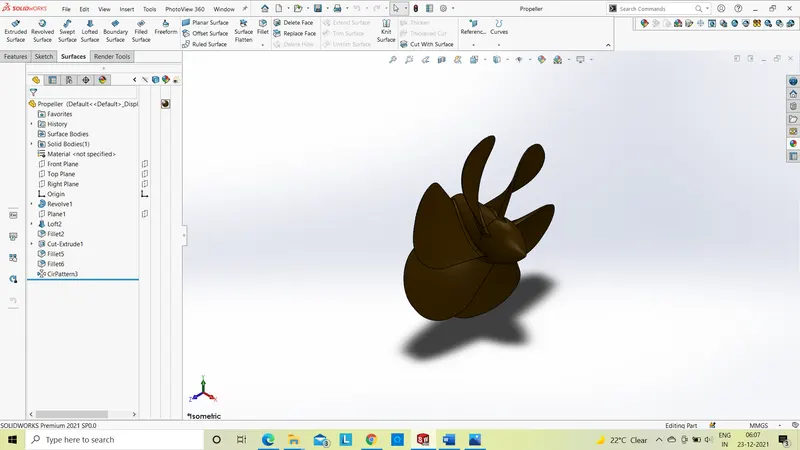
Propeller
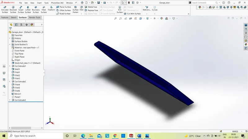
Garage Door
Radar
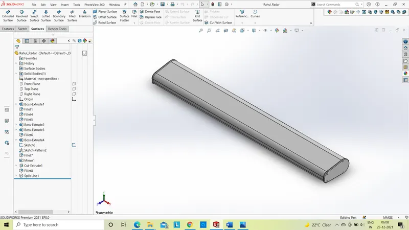
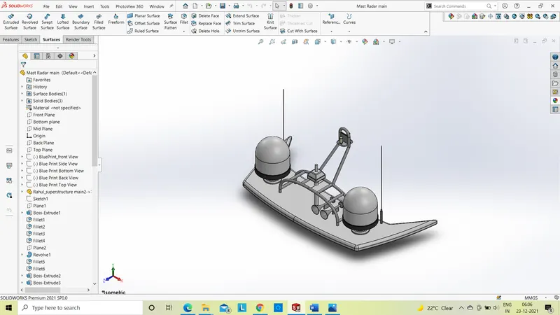
Radar Mast
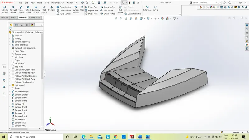
Front Seat
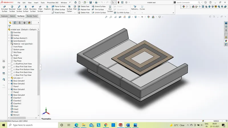
Middle Seat
Rear Seat
- Sketch
A rough drawing representing the chief features of an object.
- 2D sketch
A 2D drawing view is a representation of a 3D CAD part or assembly that is placed on a drawing sheet.
- 3D sketch
A 3D sketch tool creates geometry by using points, lines, splines and any other sketchable shape to define a profile.
Sketch commands
- Line: Using line command we draw vertical line, horizontal line
In line option there are three types of line
- Line
- Center line
- Midpoint line
- Circle: A circle is the set of all points in the plane that are a fixed distance (the radius) from a fixed point. Any interval joining a point on the circle to the center is called a radius. ... Since a diameter consists of two radii joined at their endpoints, every diameter has length equal to twice the radius.
In this command there are two types of Circle.
- Circle
- Perimeter circle
- Spline: The solid works software supports two types of splines, B-splines and style splines. You can use B-splines to create complex curves. You can define and modify them using several controls, including spline points, spline handles, and control polygons. A single B-spline can have multiple through points and spans (the region between through points). You can apply curvature constraints at each endpoint. At each through point, you can weigh the tangency vector and control the tangency direction.
Style splines, based on Bézier curves, are a good option when it is important to have a smooth curve (that is, to assure curvature continuity). You define and control the curves using control vertices. The control vertices form a control polygon, or hull of the curve. There are no through points, so a style spline has only one span between the endpoints. You can inference style splines for tangency or equal curvature. You can constrain the points and dimension the curves' sides. These curves also support mirroring and self-symmetry.
- Rectangle: A rectangle is a type of quadrilateral that has its parallel sides equal to each other and all the four vertices are equal to 90 degrees. Hence, it is also called an equiangular quadrilateral.
There are five types of rectangle solid works….
|
Corner Rectangle |
Sketches standard rectangles. |
|
|
Center Rectangle |
Sketches rectangles at a center point. |
|
|
3 Point Corner Rectangle |
Sketches rectangles at a selected angle. |
|
|
3 Point Center Rectangle |
Sketches rectangles with a center point at a selected angle. |
|
|
Parallelogram |
Sketches a standard parallelogram. |
- Arc: the part or segment of the circumference of a circle.
There are three types of arc in solid works….
|
Center point Arc |
Sketches arcs from a center point, a start point, and an end point. |
|
|
Tangent Arc |
Sketches arcs that are tangent to sketch entities. |
|
|
3 Point Arc |
Sketches arcs by specifying three points (start, end, and midpoint). |
- Ellipse: An ellipseis the locus of all those points in a plane such that the sum of their distances from two fixed points in the plane, is constant. The fixed points are known as the foci (singular focus), which are surrounded by the curve.
There are three four types of Ellipse in solid work
1)Ellipse
2) Partial ellipse
3) parabola
4) conic
- Slot: A slot is a depression in a part with a uniform cross-section along its length and is far longer than it is wide or deep.
|
Straight Slot |
Sketch a straight slot using the two end points. |
|
|
Center point Straight Slot |
Sketch a straight slot from the center point. |
|
|
3 Point Arc Slot |
Sketch an arc slot using three points along the arc. |
|
|
Center point Arc Slot |
Sketch an arc slot using the center point of the arc and the two end points |
- Polygon: A polygon is a plane figure that is described by a finite number of straight line segments connected to form a closed polygonal chain.
- Convert entities: It give you to make older sketch to new sketch with fully define feature.
- Offset Entities: It makes copy your entities to required distance.
- Mirror Entities: to mirror pre-existing 2D sketch entities on a plane.
You can mirror sketches about any these entities:
- Centerlines
- Lines
- Linear model edges
- Linear edges on drawings
- Smart Dimension
The Dimensions/Relations toolbar and the Tools, Dimensions and Tools, Relations menus provide tools to dimension and to add and delete geometric relations.
Surface modeling
Surface models define the surface features, as well as the edges, of objects. Different types of spline curves are used to create surface patches with different modelling characteristics.
Merits:
- It is less ambiguous.
- Complex surfaces can be easily identified.
- It removes hidden line and adds realism.
Demerits:
- Difficult to construct.
- Difficult to calculate mass property.
- More time is required for creation.
- Requires high storage space as compared to wire frame modelling.
- Also requires more time for manipulation.
1) Surface Extrude:
Blind: You could make your surface extrude up to where you take the extrusion arrow in drawing scheme.
Up To Vertex: If you want to make your surface extrude process up to a vertex of a feature in your drawing scheme by using Extruded Surface command, you could select this by selecting a vertex.
Up To Surface: If you want to make you extrusion up to a surface in the drawing, you could use this by selecting the surface in Extruded Surface command.
Offset From Surface: This option starts your surface extrude process from a selected plane or surface, not from the main sketch plane.
Up To Body: This feature of Extruded Surface command in Solid works, makes your surface extrude process up to a selected body with doesn’t care of whether this body have a curved structure.
Mid Plane: This option of Extruded Surface command in Solid works, makes the surface extrude process symmetrical base according to the sketch plane.
2)Revolved Surface:
Blind: Revolving up to your input angle.
Up To Vertex: Revolving up to a selected vertex in another drawing feature.
Up To Surface: Revolving up to a selected surface in another drawing feature or plane.
Offset From Surface: Revolving starting from a selected surface, not from the main sketch plane.
Mid Plane: Revolving symmetrical base around main sketch plane. The angle value you entered will be divided equally around this angle.
Feature command
- Extrude Boss: Using the modeled 2D sketch created, you are ready to turn the 2D sketch element into a 3D solid feature. The Boss-Extrude/Base feature will project a 3D model with the selected sketch or face. Blind and Mid Plane are the basic and most common directions selected when using the extrude feature.
There are some options in Extrude boss
- Sketch Plane: The plane in which the sketch was created
- Surface/Face/Plane: A different surface/face/plane than the initial sketch
- Vertex: A point
- Offset: An offset distance from the original sketch plane.
- Blind: A specified distance
- Up to Vertex: Up to a point
- Up To Surface: Up to a surface/plane/face
- Offset From Surface: A specified distance away from a surface/place/face
- Up to Body: Up to a body within the model
- Mid Plane: A specified total distance in both directions, normal to the sketch plane
- Extrude Cut: In this feature to aid in material removal of a 3D model using 2D sketches.
There are some options in Extrude cut
- Sketch Plane: The plane in which the sketch was created
- Surface/Face/Plane: A different surface/face/plane than which the sketch was created
- Vertex: A point
- Offset: An offset distance from the original sketch plane.
- Blind: A specified distance
- Through All: Through the entire part in one direction, normal to the sketch plane
- Through All - Both: Through the entire part in two directions, normal to the sketch plane
- Up To Next: Up to the next surface of the part
- Up to Vertex: Up to a point/vertex
- Up To Surface: Up to a surface/plane/face
- Offset From Surface: A specified distance away from a surface/plane/face
- Up to Body: Up to a body within the model
- Mid Plane: A specified total distance in both directions, normal to the sketch plane
- Swept Cut: A swept cut allows you to cut a model by sweeping a closed profile sketch along a path sketch. Swept cuts are great for making organic-looking cuts in geometry. In order to complete a swept cut, you must have a minimum of two sketches. One sketch will be the profile sketch, and this will be the outline of the cut. The second sketch needed will be the path sketch. The path sketch will control the direction of the cut.
.
- Loft Cut: A lofted cut is a feature that removes material between two sketch profiles. To complete a lofted cut, you must create a minimum of two separate sketches on your part that you wish to cut between. Once you have created your two sketches, you are ready to cut
5)Revolved Cut: There are many powerful cutting tools within SolidWorks besides the basic extrude cut tool. The revolved cut tool allows you to cut a profile around an axis creating complex geometry in a single feature. To set up a revolved cut it is very similar to any other feature, you start with a sketch.
6)Swept Boss: There are two main requirements to create a Swept Boss or Base: A closed profile and a path.
- Part Mirroring: In symmetric assemblies, the right and left sides may use the same parts that are mirrors of each other. Instead of creating a new part and spending the time to model and detail the mirrored part file, SolidWorks can mirror the part in relation to the parent model. This means any changes that are made to the parent will also change on the mirrored part.
To mirror a part, create a plane to mirror the part over the model or select a face, and go in the insert dropdown tab to select mirror part at the top of SolidWorks interface.
Once Mirror Part… is selected, a pop-up menu will prompt the user to select features to include in the new part before creating a new model. The most common commands to select are Solid bodies, Surfaces, Planes, and Custom properties; although, more complex features may need other commands to be transferred.
- Feature mirroring: While creating parts in SolidWorks, efficiency and accuracy are essential when working on a project. SolidWorks is equipped with a few different types of mirroring commands: sketch mirroring, part mirroring, and feature mirroring. For this blog the focus will be on feature mirroring utilizing the given top, right, and front planes to create feature mirrors.
- Fillet: Fillet/Round creates a rounded internal or external face on the part. You can fillet all edges of a face, selected sets of faces, selected edges, or edge loops.
- Revolved boss: To create a revolve feature: Create a sketch that contains one or more profiles and a centerline, line, or edge to use as the axis around which the feature revolves.
- Blind:Revolving up to your input angle.
- Up To Vertex: Revolving up to a selected vertex in another drawing feature.
- Up To Surface: Revolving up to a selected surface in another drawing feature’
- Offset From Surface: Revolving starting from a selected surface, not from the main sketch plane.
- Mid Plane:Revolving symmetrical base around main sketch plane. The angle value you entered will be divided equally around this angle.
- Reference Geometry: Reference Geometryincludes reference planes, axes, coordinate systems, and points. These are the various ways you can define a reference plane.
- Offset Distance
- Coincident with 3 vertices
- Coincident with a line and a vertex
- Angle
- Parallel
- Tangent and Parallel
- Tangent and Perpendicular
- Mid Plane
- Perpendicular at a Point
- Create a plane parallel to the screen
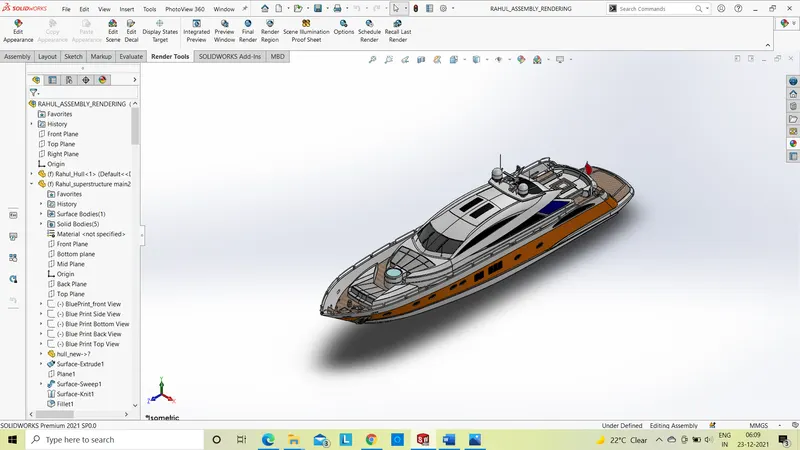
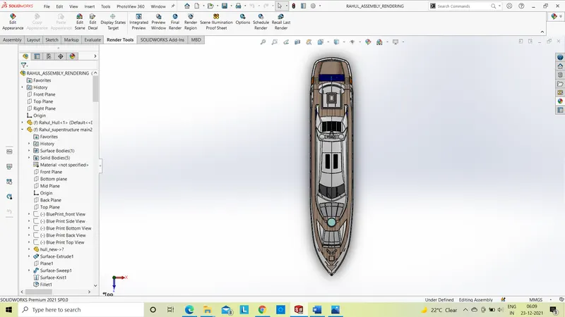
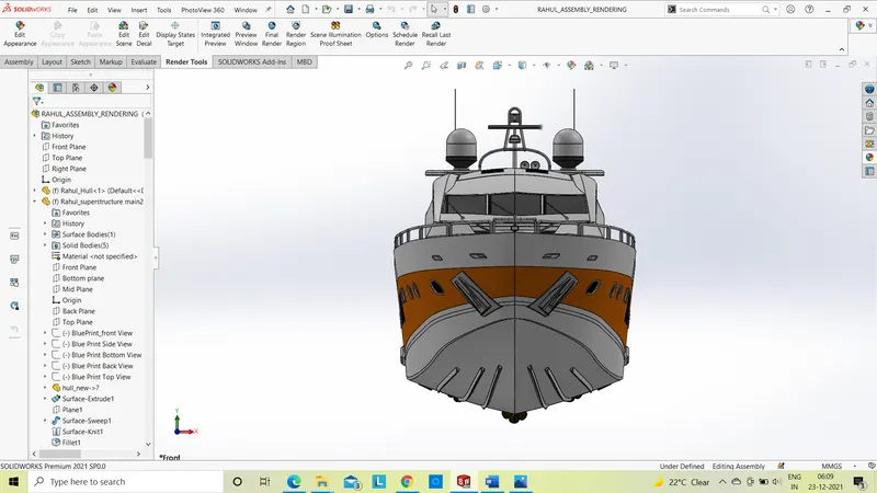
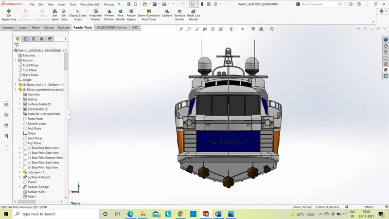
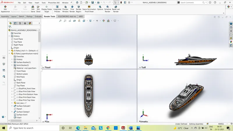
ASSEMBLY
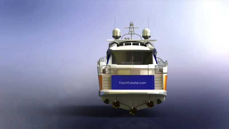
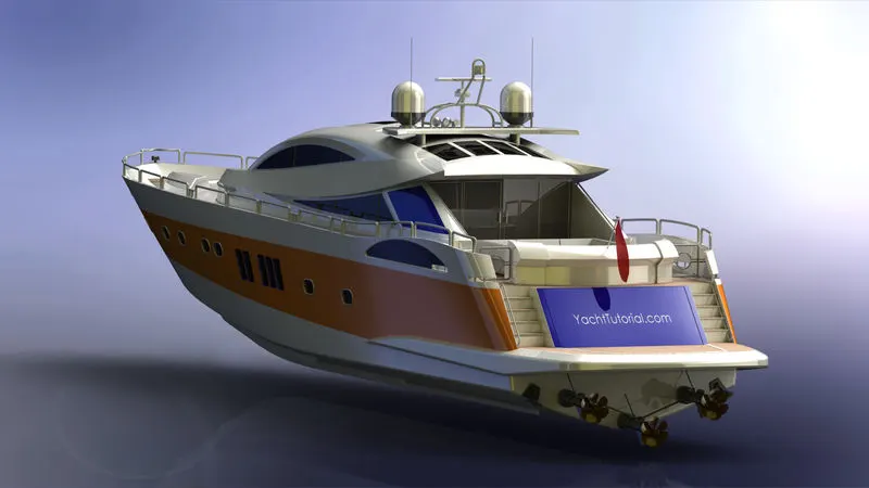
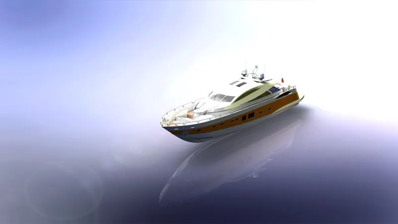
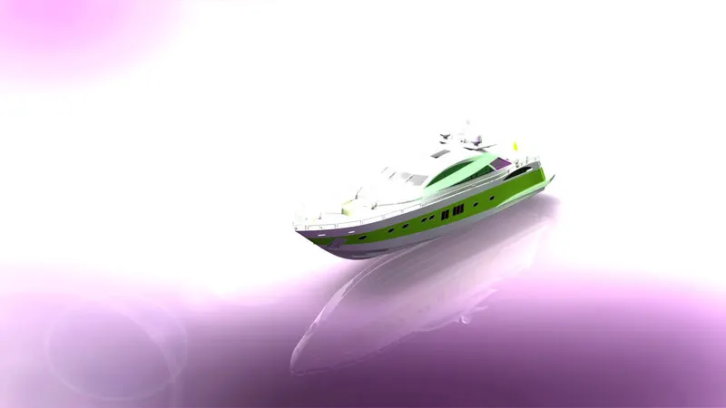
RENDERING
Conclusion
Design of YACHT using Solid Works with part Modeling, Assembly and rendering using photoview360 done Successfully.