Radar Mast & Final Assembly of Yacht
Title: Design & Assembly Of Sunseeker Predator Yacht & Rendering Using Solid Works
Objective:
This project is aimed at designing the Sunseeker Predator Yacht which involves lot of suface modeling in several parts and finally assembling all of them into a single finished model along with rendering it with approporiate colours.
Introduction:
A yacht is a sailing or power vessel used for pleasure, cruising, or racing.There is no standard definition, so the term applies to such vessels that have a cabin with amenities that accommodate overnight use. To be termed a yacht,as opposed to a boat, such a pleasure vessel is likely to be at least 33 feet (10 m) in length and may have been judged to have good aesthetic qualities.
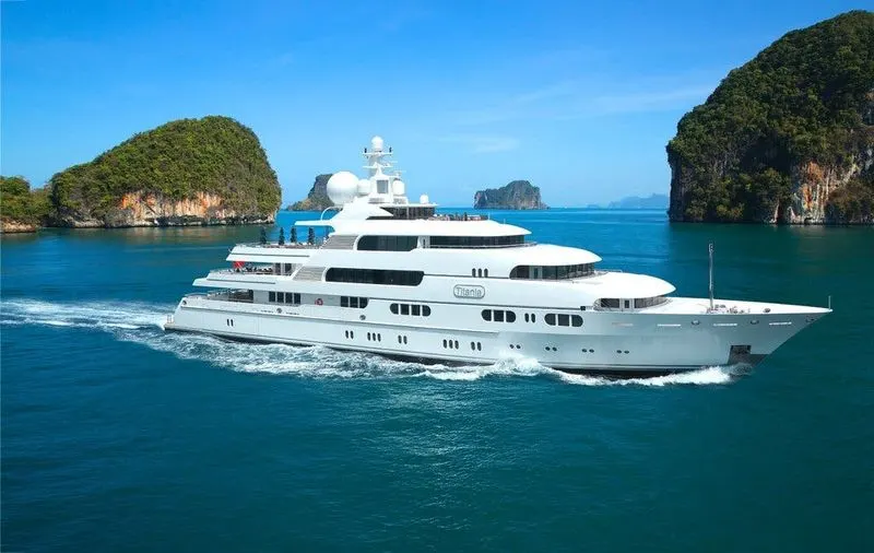
The term, yacht, originates from the Dutch word jacht and originally referred to light,fast sailing vessels that the Dutch Republic navy used to pursue piratesand other transgressors around and into the shallow waters.
Design Flow Chart:
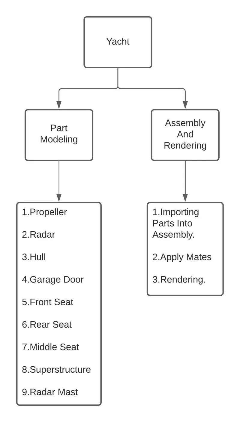
I.Part Modeling :
1.Propeller:
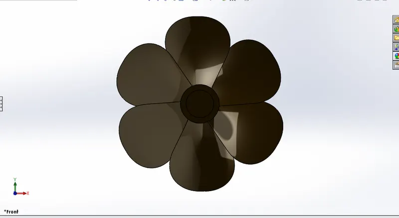
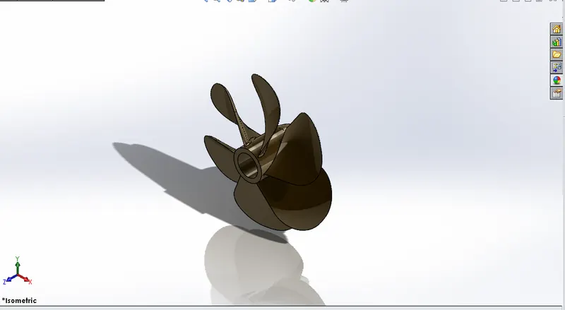
A propeller is a rotating fan-like structure that is used to propel the ship by using the power generated and transmitted by the main engine of the ship.The transmitted power is converted from rotational motion to generate a thrust which imparts momentum to the water, resulting in a force that acts on the ship and pushes it forward.A ship propels on the basis of Bernoulli’s principle and Newton’s third law. A pressure difference is created on the forward and aft side of the blade and water is accelerated behind the blades.
The thrust from the propeller is transmitted to move the ship through a transmission system which consists of a rotational motion generated by the main engine crankshaft, intermediate shaft and its bearings, stern tube shaft and its bearing and finally by the propeller itself.
Tools/Features Used In Modeling:
-Line,Circle,Rectangle
-Extrude,Loft,Cut Extrude,Fillet,Chamfer
Modeling Procedure:
- Sketch the centre part of propeller and revolve the sketch.
- And then dimension the new plane of rewuired distance.
- On the centre part of the propeller draw a rectangle of shown dimension in a angled manner.
- Same as it draw another rectangle on the newly created plane in a diffrent angle.
- Make the Loft by selecting both the sketches and Fillet to it.
- Finally pattern the foiled shaped wings of the propeller in 360 degrees and give appropriate apperance to them.
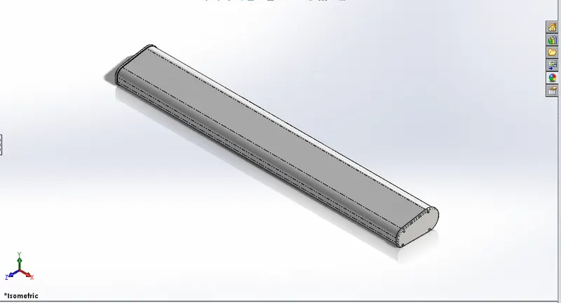
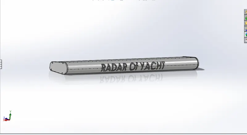
2.Radar:
Marine radars are X band or S band radars on ships, used to detect other ships and land obstacles, to provide bearing and distance for collision avoidance and navigation at sea. They are electronic navigation instruments that use a rotating antenna to sweep a narrow beam of microwaves around the water surface surrounding the ship to the horizon, detecting targets by microwaves reflected from them, generating a picture of the ship's surroundings on a display screen.
Radar is a vital navigation component for safety at sea and near the shore. Captains need to be able to maneuver their ships within feet in the worst of conditions and to be able to navigate "blind", when there is no visibility at night or due to bad weather. In addition to vessel-based marine radars, in port or in harbour, shore-based vessel traffic service radar systems are used by harbormasters and coast guard to monitor and regulate ship movements in busy waters.
Tools/Features Used In Modeling:
-Line,Circle,Rectangle
-Extrude,Mirror,Cut Extrude,Fillet,Split Line
Modeling Procedure:
- Sketch the shape of the radar in the middle plane and extrude by selecting Midplane option in the Boss Extrude feature.
- Add filleting to the ends of the radar.
- Use Extrude option by using convert entities to show ends are closed and bolted.
- And write the text in the sketch and use Split option to engrave the sketch on the Radar.
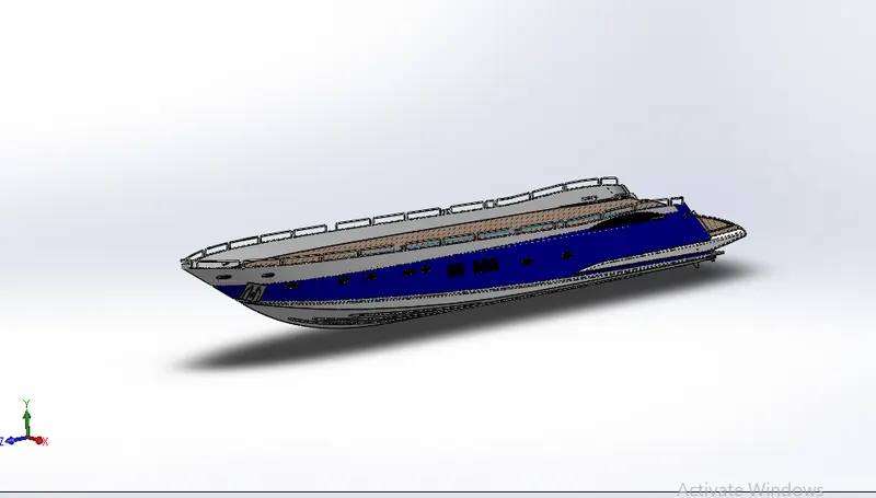
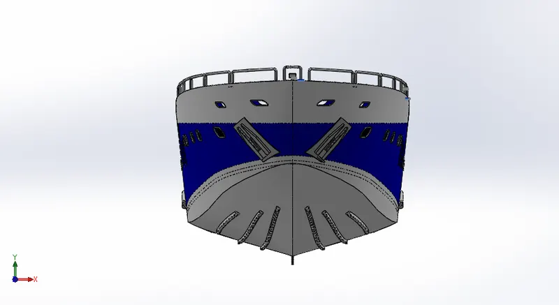
3.Hull:
The main body of a vessel from the deck down. It does not include rigging, superstructure, machinery, or equipment.The hull of a ship is the most important as well as the most noticeable part of the ship. It is the watertight part of any vessel or even boat. It is defined as the water-tight enclosure of a ship. It protects the cargo and the machinery of the ship. It can also protect the boat from flooding and other structural damage. It is the part of the vessel which meets the ocean. The point or the line at which the hull of a ship meets the surface of the water is called the waterline. The hull of a ship can vary greatly depending upon the size or the type of the ship or vessel. Any structure like the deck of a ship, the mast, etc. can lie above or atop the hull of a ship.
Tools/Features Used In Modeling:
-Line,Circle,Rectangle,Circle,Offset,Convert Entities,Project Curve
-Extrude,Mirror,Cut Extrude,Fillet,Split Line,Loft,Surface Trim,Surface Extrude
Modeling Procedure:
- Sketch the outer hull lines in atleast two views by placing the blueprint as reference.
- And use Project curve option to convert those two lines on different planes into 3D curves.
- Make these kind of curves appropriately and use Loft feature to make the outer surface.
- Trim the surface wherever both the surfaces meets excessively and Knit the surfaces for making them as single surface.
- After that all the outer surfaces after knitting should turn into a solid body.
- In that solid body cut the shapes of the required decks and give appropriate apperances.
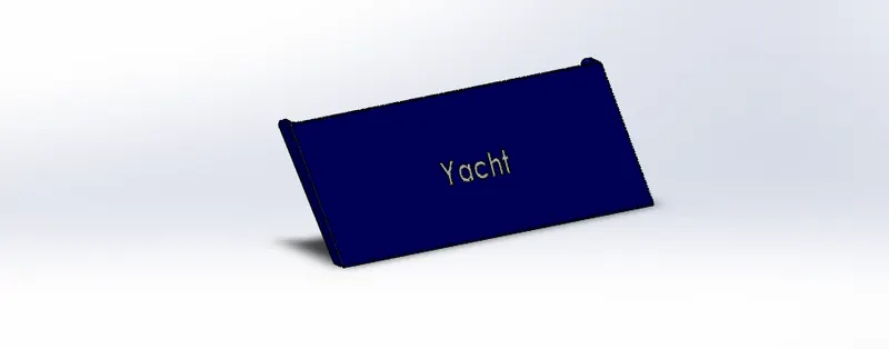
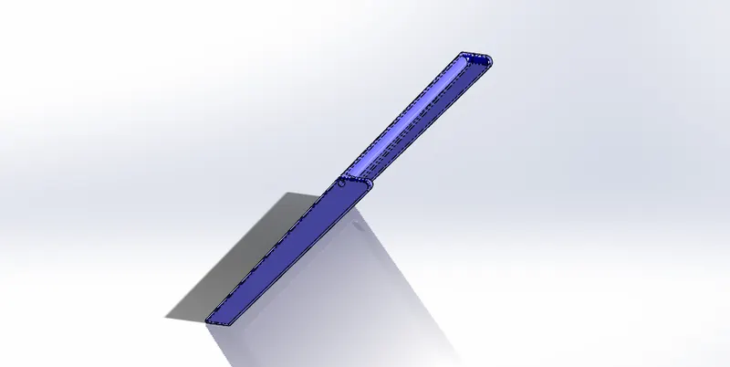
4.Garage Door:
It is used to cover the garage in the yacht which is used to park the vehicles or the lifeboats in the yacht.It is simple openable door provided with hinges for easy operating.
Tools/Features Used In Modeling:
-Line,Circle,Rectangle.
-Extrude,Mirror,Cut Extrude,Fillet,Shell
Modeling Procedure:
- Draw a rectangle with tapered shape and make shell of thickness 100mm.
- And cut the unwanted body of the part make it to look as the simple door with hinges.
- Engrave name on the door as your wish and give the appearance to it.
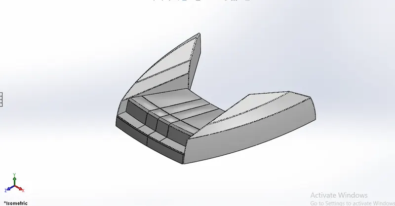
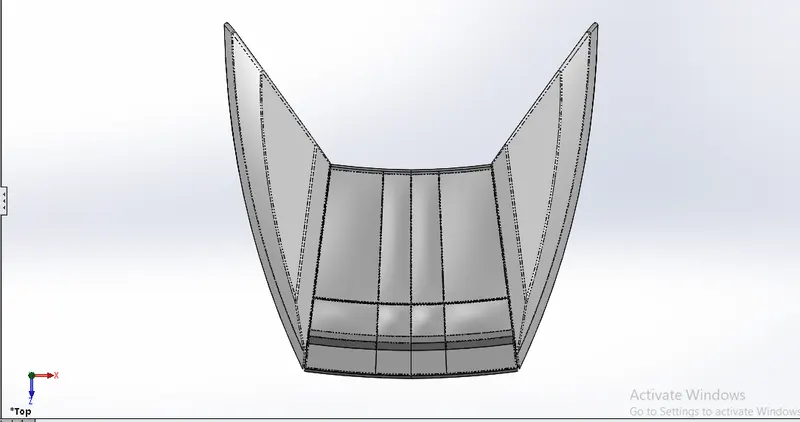
5.Front Seat:
This seat is located at the front most part of the ship giving a stunnig view of cruising ship in the ocean along all the fresh breeze of air.
Tools/Features Used In Modeling:
-Line,Circle,Rectangle,Circle,Offset
-Extrude,Mirror,Cut Extrude,Fillet,Loft,Surface Trim,Surface Extrude,Surface Sweep,Surface Fill,Dome,Revolve
Modeling Procedure:
- Draw a triangular shaped sketch and make surface sweep.Then join the swepth surface ends on the bottom in v shape extrude it too.
- After extrude the trim any extra surfaces or body present to align perfectly.
- Use loft and surface fill to completely make it as a solid body.
- Draw a shape of seat body at the right side of the triangular solid body just we created.
- Revolve it to 10 degrees and model the cuhions thr body of the seat.
- Finally add the appearnce as it to look like seat and mirrror it form the other side to form a complete seat.
6,7.Rear & Middle Seat:
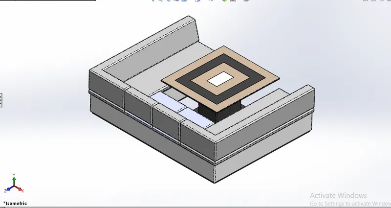
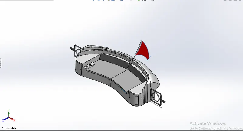
Rear seat is located at the back of the yacht with a place to relax.It also has a flag mounted behind the seat.Middle seat comes with a table at the centre to read or use it as dining area.
Tools/Features Used In Modeling:
-Line,Circle,Rectangle,Circle,Offset
-Extrude,Mirror,Cut Extrude,Fillet,Surface Fill,Dome,RevolveLoft,Surface Trim,Surface Extrude,Surface Sweep
Modeling Procedure:
- The modeling procedure alomost remains same for the Centre and Rear Seat.
- It is just to make the desired shape model as per the rewuirement using features in the CAD softwares.
- At last adding the appropriate colurs to the body or surfaces as it looks good.
8.Superstructure:
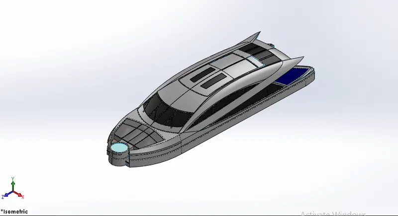
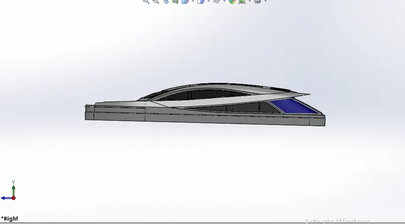
A superstructure is an extended construction of any building or platform that rises above the rest of the building or platform in a distinct manner.Thus, superstructure means to add a construction to an already existing structure. In ships this is the name given to the part of the ship that emerges from the deck.The superstructure includes beams, columns, finishes, windows, doors, the roof, floors, and anything else. The parts of the superstructure are much lengthier than the parts of the substructure.The superstructure of a ship is where people will spend most of their time. This area includes the first and second floors inside a yacht and any number of floors.
Tools/Features Used In Modeling:
-Line,Circle,Rectangle,Circle,Offset,Convert Entities,Project Curves,Points,Arcs
-Extrude,Mirror,Cut Extrude,Fillet,Surface Fill,Dome,RevolveLoft,Surface Trim,Surface Extrude,Surface Sweep,Shell,Thin,Knit,Split Line,Offset Surface,Rules Suface,Delete Face
Modeling Procedure:
- This is one of most complicated part in the yacht modeling, it deals with lot of surfaces and making them into solid bodies with exact trimming and knitting surfaces without leaving any gaps.
- Draw the curves by referencing with the blueprints of the yacht and use Project curves to make them into 3D curves.
- Then join the curves by usinf loft suface and fill to form a valid surface of the yacht superstructure.
- Trim and delete face wherever extra extruded sufaces are met and make all the surfaces into one surface by knitting all of them.
- Now the it has shown as solid body in the feature tree instead of suface once it is completely closed without any gaps.
- Cut the shapes of the windows and doors on the superstructure and add the vipers,jacuzzi and appearance decals to all the required sufaces.
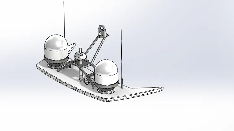
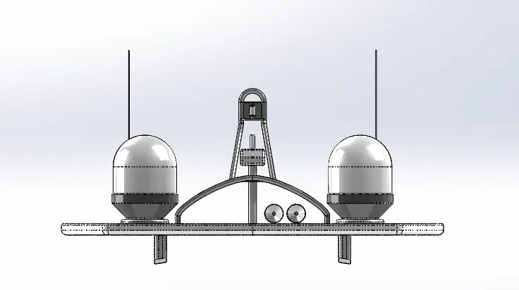
9.Radarmast:
Radarmst and communication tower of the yacht is located at the top most area.Radar rotates by throughing the magnetic waves and receiving the singnals to analyse if there is any obstacles arriving.
Tools/Features Used In Modeling:
-Line,Circle,Rectangle,Circle,Offset,Convert Entities,Project Curves,Points,Arcs.
-Extrude,Mirror,Cut Extrude,Fillet,Revolve,Loft,Surface Trim,Surface Extrude,Shell.
Modeling Procedure:
- First draw the bottom area of the radar mast by using sketch and surface extrude.
- Then reference the blueprint to draw the remaining part of the model
- After completing one side mirror it along with appearances option selected.
II.Assembly & Rendering:
- At last after modeling all the parts of the yacht Open assembly in CAD software and insert the parts in the appropriate by using mates.
- Finally we will get a completed assembly model.
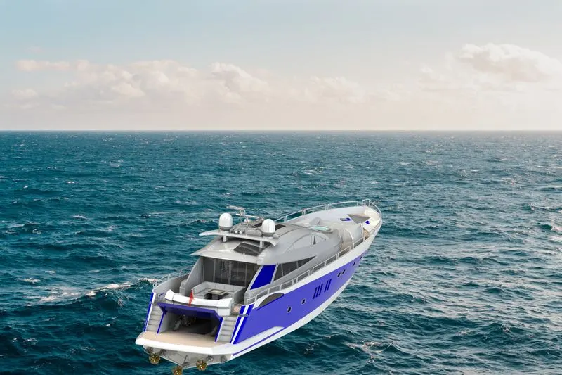
- Render the model by using photoview 360 or any other rendering software save the images of them.
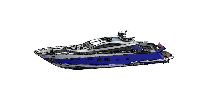
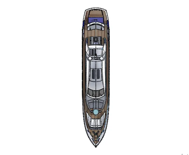
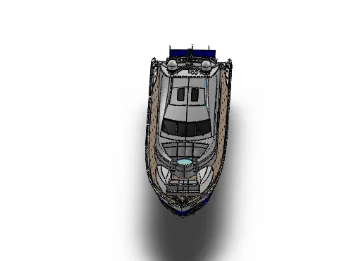
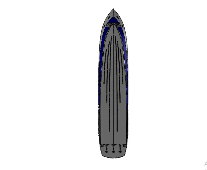
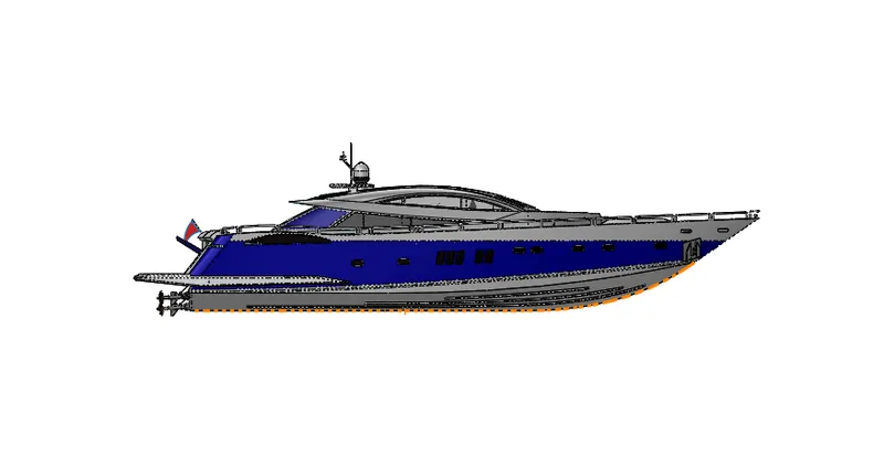
Rendered Images:
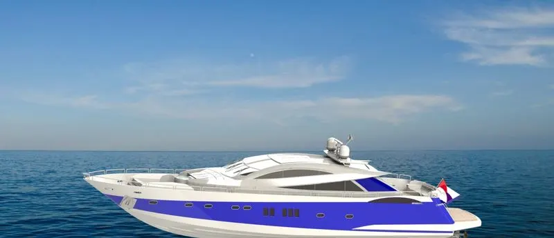
Conslusion:
Thus the design and assembly of Sunseeker Predator Yacht is done along with rendered images by using Solidworks,Photoview 360.