Designing,Assembly Of American Chopper & Rendering Using Photo View 360
Title: Designing,Assembly Of American Chopper & Rendering Using Photo View 360
Objective:
The objective of this project is to design a chopper from scratch by modeling all the parts and assembly with help of blueprint by using appropriate mate commands in Solid Works. And photo realistic rendering of assembly in Photo View 360.
Introduction:
American Chopper Motorcycles:
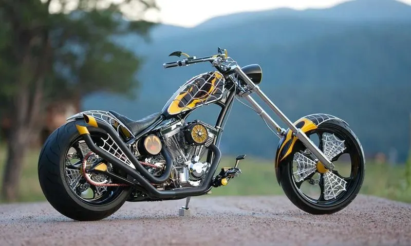
OCC Custom American Chopper
Orange County Choppers(American Choppers) bikes are motorcycles featured on the television series American Chopper built by Orange County Choppers (OCC) for a specific corporate or celebrity customer. Theme bikes are motorcycles in which the theme of the motorcycle takes priority over everything else, influencing the frame dimensions, paint scheme, and overall 'feel' of the motorcycle. Customer bikes are built for and generally to the specifications of a particular customer. Although the customers typically give OCC creative freedom to do what they will, some clients have a specific idea in mind and expect OCC to reproduce their mental picture literally.Customers use the bikes for promotional purposes at tradeshows or auction them off as a charity fundraiser.
Solid Works:
SolidWorks is a solid modeling computer-aided design (CAD) and computer-aided engineering (CAE) computer program published by Dassault Systèmes, that runs primarily on Microsoft Windows. . It uses the principle of parametric design and generates three kinds of interconnected files: the part, the assembly, and the drawing. Therefore, any modification to one of these three fileswill be reflected in the other two. Solidworks helps you perform 2D and 3D modelling, and this CAD software is known for its ease-of-use and intuitiveness.
Solidworks software enables us to design very precise 3D objects, develop products, double-check your file's design, maintain a library of your 3D files, create 2D drawings, create images and animations of your 3D objects, estimate the manufacturing cost of your 3D objects.
Photo View 360:
PhotoView 360 is available in both SOLIDWORKS Premium & SOLIDWORKS Professional. PhotoView 360 gives you the ability to generate high-quality, life-like images right within the SOLIDWORKS application. PhotoView 360 gives you the tools to Apply Appearances, Apply scenes, Decals, Integrated preview, Rendering options, Final render and Rendering templates.
PhotoView 360 isn’t only a fantastic feature within SOLIDWORKS, but is a great tool for sales and marketing. The ability to preview your product with a real life background and a realistic light source, lets you visualise your product without even having to build a prototype.This gives your marketing team a powerful tool, as it can create campaigns and marketing material based around your high definition rendered images (without the costs of building prototypes).
If you’re creating a product for a client they can visualise the design in whatever background they wish and can recommend changes based upon the image as opposed to a model, again, saving time and money.
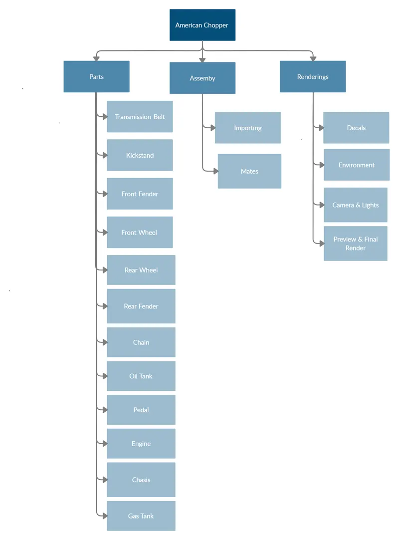
Design Methodology and Flow Chart :

Description Of Tools Used In Designing :
Sketch Tools:
Smart dimension: Creates a dimension for a selected sketch entity.
Line: Sketch a horizontal, vertical, or angled line. Double click to end the line. Also start a line by holding the left mouse button and end the line by releasing the button. The centerline tool can be accessed through the drop down arrow and performs the same way.
Corner Rectangle: Sketch a rectangle or square. Each rectangle tool shows the user inputs in the tool by denoting the mouse “clicking” points as small red circles. Additional tools such as parallelogram, center rectangle, 3 point corner rectangle, and 3 point center rectangle can be found under the drop down arrow. These function the same as the corner rectangle tool.
Polygon: Sketched a polygon. Allows the user to input the number of sides on the polygon. Inserts pre-defined reference geometry to minimize sketch dimensions.
Tangent Arc: An incomplete circle defined by its tangency to the sketch entity. Specify the tangent arc by left clicking a sketch endpoint and then left click to specify the endpoint of the arc. Additional tools such as center point arc and 3 point arc can be found under the drop down arrow. They function similarly to the tangent arc by asking the user to input the defining arc points
Circle: There are two methods of drawing circles, Center Circle and Perimeter Circle. Center circle sketches center-based circles.Perimeter circle sketches perimeter-based circles. These are sketched by defining three points. This type of circles is used when we have to create a circle passing through three points, you have to create a circle passing through three pointsm you have to specify all three points to create this circle.
Sketch Fillet: A tangent arc inbetween two sketch entities. Specify the radius by left clicking in the radius text box in the property manager
Spline: A two or three dimensional curve defined by a set of control points. Points within a spline can be added or deleted by left clicking on the spline point and saying delete, or add spline point.
Ellipse: Sketches a complete ellipse. Left click in the design space to place the center of the ellipse. Next, define the major and minor axis by left clicking and then dragging the cursor to the desired position.
Plane: Inserts a plane in a 3D sketch. Must be in the 3D sketching tool to use it. Useful as construction geometry to help define the sketch entity
Trim Entities: Trim sketch entities to the desired shape. To trim a section left click on the desired sketch entity to cut away.
Display/Delete Relations: In order to define a sketch the user can relate sketch entities to each other. These relations both defined by the user and solidworks can be veiwed by selecting the display/delete relations tool.
Convert Entities: Project a sketch entity, face, edge, curve, or contour onto the open sketch plane. To convert entities left click on the desired sketch, face, edge, contour, or curve and then left click on convert entities. A new sketch will be created on the plane fully defined using the geometry of the selected entity.
Offset Entities: Copy a sketch entity to a specified distance from the original entity. Must have a sketch entity already drawn and selected to use this tool. Select the offset distance in the property manager by left clicking in the offset distance text box and specifying the value.
Sketch Picture: Insert an image file into the background of a sketch. This allows the user to 2D sketches based off of the image. Use the sketch picture property manager to alter the inserted image.
Mirror Entities: Create a reflected copy of a desired entity about a centerline or axis. Make sure the entities to mirror box is highlighted in the property manager. Select the desired entities to mirror, or replicate by left clicking on each. Select the mirror about box in the property manager by left clicking in the text box. Then left click the centerline/axis. A preview will appear in the design space. Press (or enter) to accept the mirror or (or esc) to cancel in the property manager, and exit the mirror entities tool.
Pattern: Used to create same objects in an particular way
1.Linear Sketch Pattern: A linear pattern creates a copy of a feature similar to grid. To define a lilnear pattern, required things are specify the direction of the patterns the number of copies in each direction and the distance between copies.
2.Circular Pattern: The circular pattern is very similar to the linear however, instead of patterning along dimensions, it patterns about an axis.
Features:
Boss Extrude : Creates a solid based on the sketch with entered thickness
Fillet : It creates a rounded internal or external face on the part. It is possible to fillet all edges of a face, selected sets of faces, selected edges or edges loops.
Extrude Cut : This tool is used to remove material by projecting a sketched section normal to the sketching plane. Extrude cut feature helps to remove materials from 3D models, but only in linear manner.
Section View : In a section view for part or assembly document the model displayed as if cut by planes and faces that to specify for showing the internal construction of the model.
Loft: Loft creates a feature by making transitions between profiles. A loft can be a base, cut or surface. You create a loft using two or more profiles. Only the first last or first and last profiles can be points. All the sketch entities, including guide curves and profiles can be contained in a single 3D sketch.
Shell: The shell tool hollows out a part, leaves open the faces you select and creates thin walled features on the remaining faces. If you do not select any face on the model you can shell a solid part, creating a closed hollow model. You can also shell a model using multiple thicknesses.
Dome : Creates a dome on the face selected.
Revolved Cut : This feature helps to remove materials from3D models possess axis symmetry. Revolved cut removes materials by revolving a closed profile a alomg an its axis.
Combine: This common function allows us to add two bodies together and keep the area that is common to them.
Mirror : It creates a base by moving a profile along a path , according to this profile must be closed for a base feature. The path may be open or closed.
Blocks : This command is a saved sketch that can prevent redrawing the same sketch at multiple times.
Revolve Boss/ Base: It is used to create a solid feature by revolving a sketch about an axis. It is mostly used for creating cylinders, pipes and tubes or any sold objects which has an axis.
Split: This feature is used to create multiple parts from an existing part. It is possible to split one or more solid or surface bodies. To split a sketch, the trimming sketch must extend past the boundries of the sketch to split.
Pierce Relationship: These relations can be added to sketch points and an axis,edge,line or spline. They are especially useful for ensuring that a coincident relationship is formed between entities of varying axis.
Surface Commands:
Trim Surface: It is possible to use a surface,plane or sketch as trim tool to trim intersecting surfaces.
Knit Surface: The Knit surface tool is use to combine two or more faces.
Projected Curve: It is a tool used to form 3D curves from two 2D curves from the two different planes.
Sweep Surface: These surfaces are generated from a section curve positioned along a path. Various sweep types are available to extend the sweep surface.
Surface Loft: These surfaces are generated by multiple 3D Curves or existing edges creating a smooth tangency between the selected curves. Match points are created between each selection denoting the orientation and path of the loft surface.
1.Designing Of Parts/Components :
There are 13 parts present in American Chopper design.They are as follows:
A.Transmission Belt:
A belt is a loop of flexible material used to link two or more rotating shafts mechanically, most often parallel. Belts may be used as a source of motion, to transmit power efficiently or to track relative movement. Belts are looped over pulleys and may have a twist between the pulleys, and the shafts need not be parallel.
In a two pulley system, the belt can either drive the pulleys normally in one direction (the same if on parallel shafts), or the belt may be crossed, so that the direction of the driven shaft is reversed (the opposite direction to the driver if on parallel shafts). As a source of motion, a conveyor belt is one application where the belt is adapted to carry a load continuously between two points. The belt drive can also be used to change the speed of rotation, either up or down, by using different sized pulleys.
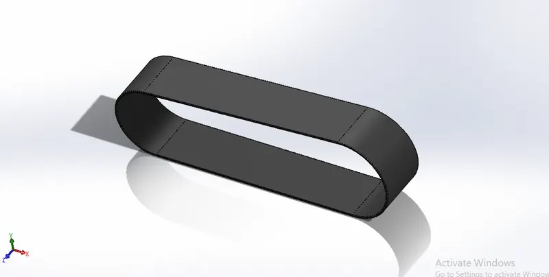
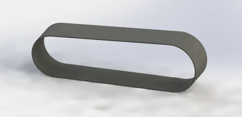
Commands Used In Modeling
Sketching: Line, 3 Point Arc, Offset Entities
Features: Extrude, Fillet 1mm
Appearance: Matte Rubber
Modeling Procedure:
- Sketch on Front Plane and draw a line of 350 mm horizontally
- And draw a line above the horizontal line in an inclined way.
- Use two three point arcs of radius 60 mm and 70 mm on both sides as shown in the image.
- Make the two end points of arcs vertical and tangent to those horizontal lines.
- Offset the lines by 3.5 mm and press exit sketch.
- Extrude the whole sketch by xx mm and finally add fillets of 1mm to the edges.
- Apply the Matte Rubber appearance to the part and save.
B.Kick Stand:
A kickstand is a device on a bicycle or motorcycle that allows the bike to be kept upright without leaning against another object or the aid of a person. A kickstand is usually a piece of metal that flips down from the frame and makes contact with the ground. It is generally located in the middle of the bike or towards the rear. Some touring bicycles have two: one at the rear, and a second in the front.
A side stand style kickstand is a single leg that simply flips out to one side, usually the left side, and the bike then leans against it. Side stands can be mounted to the chain stays right behind the bottom bracket or to a chain and seat stay near the rear hub. Side stands mounted right behind the bottom bracket can be bolted on, either clamping the chain stays, or to the bracket between them, or welded into place as an integral part of the frame.
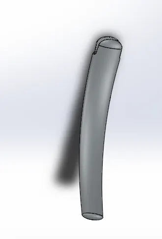
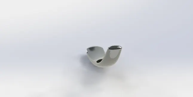
Commands Used In Modeling
Sketching: Ellipse,Spline
Features: Pierce,Extruded Cut,Lofted Boss/Base,Extruded Boss/Base
Appearance: Chrome Steel
Modeling Procedure:
- Draw an ellipse on the front plane and make it center point coincident with the origin.
- The spline created from the origin in the mid plane should be dimensioned as required.
- A new plane was generated normal to the spline using plane tool from the reference geometry, another r ellipse was sketched and its centre point must be pierced through with the end point of the spline.
- Then Loft the sketches created and add domes to the both ellipse shaped ends.
- Now on bottom side a rectangular extruded cut was made on the mid plane using Extruded cut through the whole material.
- A circular holder was extruded in between the lower side of the kickstand has been split away using split tool for touching the ground perfectly.
- Add the required fillets for the edges and apply the chrome steel material appearance.
C.Front Fender:
Fender is the American English term for the part of an automobile, motorcycle or other vehicle body that frames a wheel well (the fender underside). Its primary purpose is to prevent sand, mud, rocks, liquids, and other road spray from being thrown into the air by the rotating tire. Fenders are typically rigid and can be damaged by contact with the road surface.
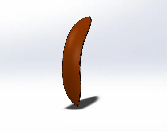
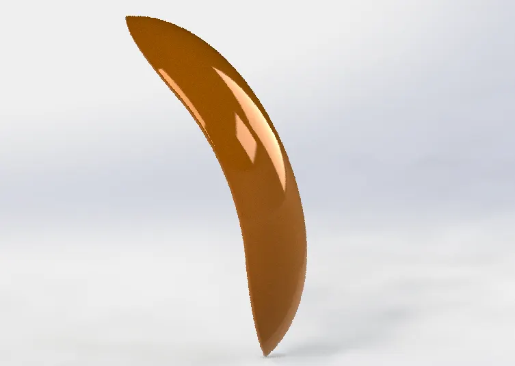
Commands Used In Modeling
Sketching: 3 Point Arc,Offset,Spline,Line
Features: Split,Fillet,,Revolve,Dynamic Mirror Entity
Appearance: Painted Siena
Modeling Procedure:
- Draw a 3 Point arc above the origin in the front plane, apply the vertical relation with the origin. Offset inwards to extrude ,make it closed sketch using extended entities, trim entites.
- Make the sketch revolve across the horizontal construction line at origin by giving angles.
- Remove the unwanted area using the split tool and apply fillet.
D.Rear Fender:
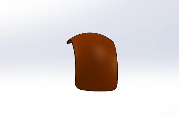
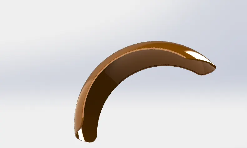
Rear fender is located at the back side of the vehicle guarding the rear wheel to prevent the mud,sand and other materials to touch the body of vehicle and also to stop them spreading on the rider.
Commands Used In Modeling
Sketching: 3 Point Arc,Offset,Spline,Line
Features: Split,Fillet,,Revolve,Dynamic Mirror Entity
Appearance: Painted Siena
Modeling Procedure:
- The procedure to draw the rear fender is same as the front fender.
- Draw a 3 Point arc above the origin in the front plane, apply the vertical relation with the origin. Offset inwards to extrude ,make it closed sketch using extended entities, trim entites.
- Make the sketch revolve across the horizontal construction line at origin by giving angles.
- Remove the unwanted area using the split tool and apply fillet.
E.Chain:
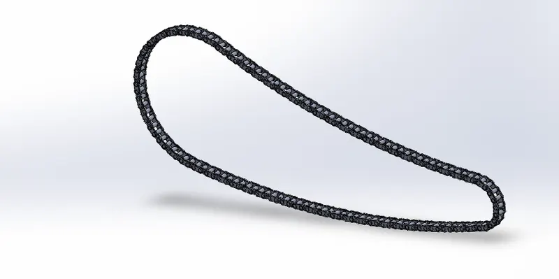
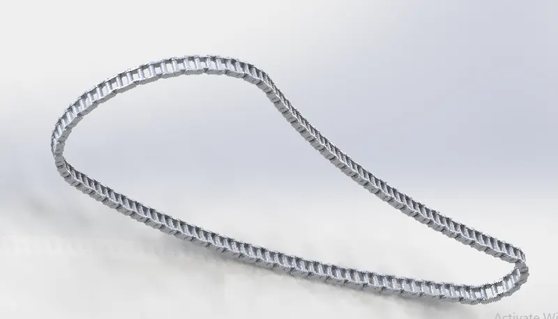
Chain drive is a way of transmitting mechanical power from one place to another. It is often used to convey power to the wheels of a vehicle, particularly bicycles and motorcycles. It is also used in a wide variety of machines besides vehicles.
Most often, the power is conveyed by a roller chain, known as the drive chain or transmission chain,[1] passing over a sprocket gear, with the teeth of the gear meshing with the holes in the links of the chain. The gear is turned, and this pulls the chain putting mechanical force into the system.
Commands Used In Modeling
Sketching: 3 Point Arc,Line,Straight Slots
Features: Extrude,Curve driven pattern,Blocks,Fillet,Mirror Entity
Appearance: Chrome Steel
Modeling Procedure:
- Sketch the chain path with two 3-point arcs of same dimensions as the rear and front sprocket with diameter 289 and 99mm respectively.
- Give 650 mm as the horizontal dimensions and 147 mm as vertical dimensions between the 2 arc centers.
- Two three point arcs of dia 1500 mm are drawn to join the arcs.
- Create sketch which is used to create inside and outside chain links, make a block and insert blck on the larger end of the drawn circle pins.
- Extrude again to create plates by selecting the remaining part in blocks and apply fillet.
- Use a curve driven pattern to get required number of pins and plates over the curve.
F.Oil Tank:
Oil tanks are generally associated with a dry sump lubrication system, while a wet sump system uses the crankcase of the engine to store the oil. Oil tanks are usually constructed of aluminum alloy and must withstand any vibration, inertia, and fluid loads expected in operation.
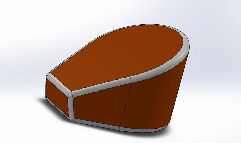
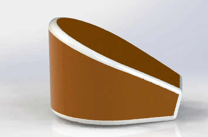
Commands Used In Modeling
Sketching: 3 Point Arc,Line
Features: Extrude,Combine,Fillet,Shell
Appearance: Painted Siena
Modeling Procedure:
- Draw a 3 point arc and give relation and the required dimensions to extrude.
- Sketch on the front plane by drawing a spline,line as suggested to make a desired shape of the sketch
- Extrude it by midplane and combine the separated bodies, and finally apply fillets.
G.Pedal:
It is also known as foot rest .In this bike it is used for both gear changing and resting of the foot.
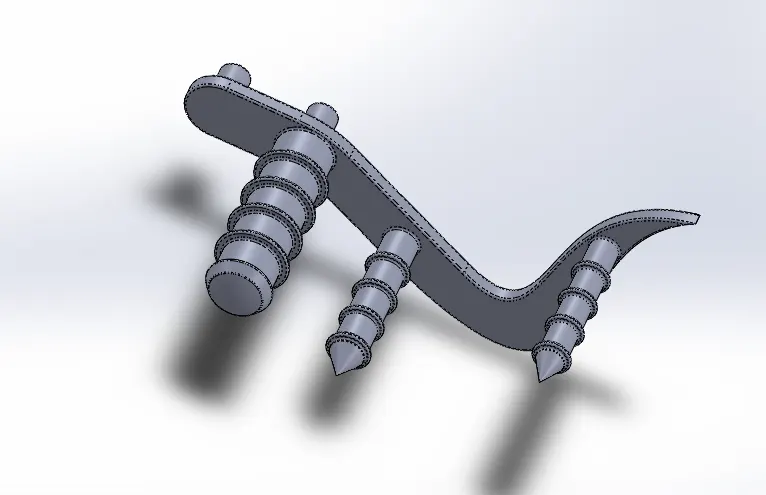
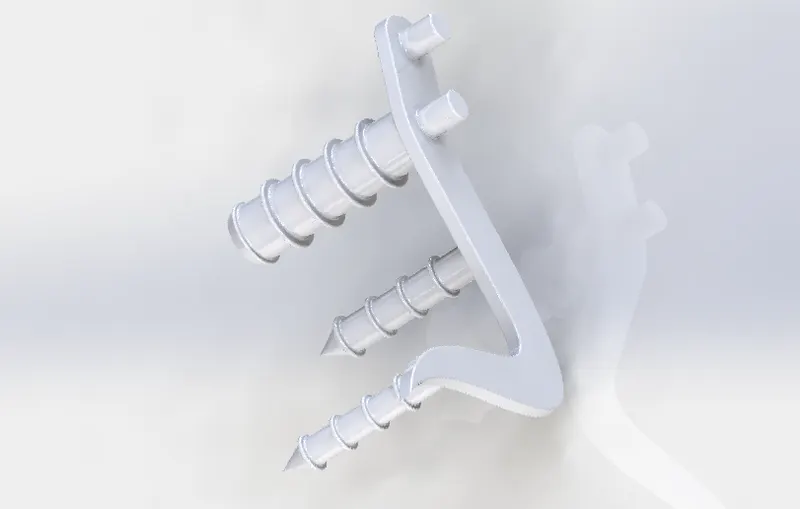
Commands Used In Modeling
Sketching: Circle,Line,Spline
Features: Revolve,Combine,Fillet,Dome,Lineat Pattern,Chamfer,Fillet
Appearance: Chrome Steel
Modeling Procedure:
- Create the desired sketch on the front plane and use fillets of the required dimensions.
- Extrude the sketch, and extrude the two circles of diameter in reverse direction.
- Sketch the rectangular shaped lines on the front plane and revolve the sketch and merge results, make a dome on the end face of the revolved part.
- Then circular ectrude was created using fillet, offset,chamfer and linear pattern options.
H.Front Wheel:
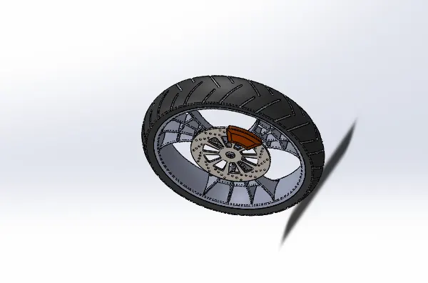
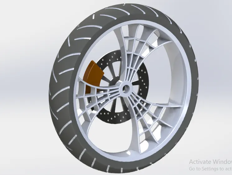
Motorcycle wheels are made to cope with radial and axial forces. They also provide a way of mounting other critical components such as the brakes, final drive and suspension. Wheels, and anything directly connected to them, are considered to be unsprung mass. Traditionally motorcycles used wire-spoked wheels with inner tubes and pneumatic tyres. Although cast wheels were first used on a motorcycle in 1927, it would not be until the 1970s that mainstream manufacturers would start to introduce cast wheels on their roadgoing motorcycles. Spoked wheels are usually made using steel spokes with steel or aluminium rims. Cast wheels are predominantly made from an aluminium-alloy, but can also be made from more-exotic materials, such as magnesium content alloy or carbon fibre.
Commands Used In Modeling
Sketching: Circle,Line,Spline,3 Point Arc,Sketch Fillet,Extend Entities, Centre Point Rectangle,Trim
Features: Revolve,Extrude,Offset,Revolved Cut,Circula Pattern,Fillet,Chamfer
Appearance: Matte Rubber for Tyre,Chrome for Rim,Siena for Caliper
Modeling Procedure:
- Wheel in this model is a multi body part contains Rim,Tyre,Caliper,Brake Disc.
- Rim was designed by creating the required sketch on the front plane and applying proper dimensions.
- The created sketch was used to create revolve and circular pattern.
- And spider web shaped rotor is designed and fillets were added and applied the proper appearance.
- Then design the caliper by drawing arc and using trim, extrude commands.
- Finally tyre has been designed by drawing the required sketch on the front plane and revolved around the rim.
- Then Cuts on the tyres are drawn to provide grip for tyres as per instructed dimensions.
- Apply appearances for all the bodies appropriately.
I.Rear Wheel:
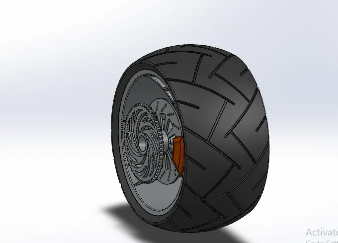
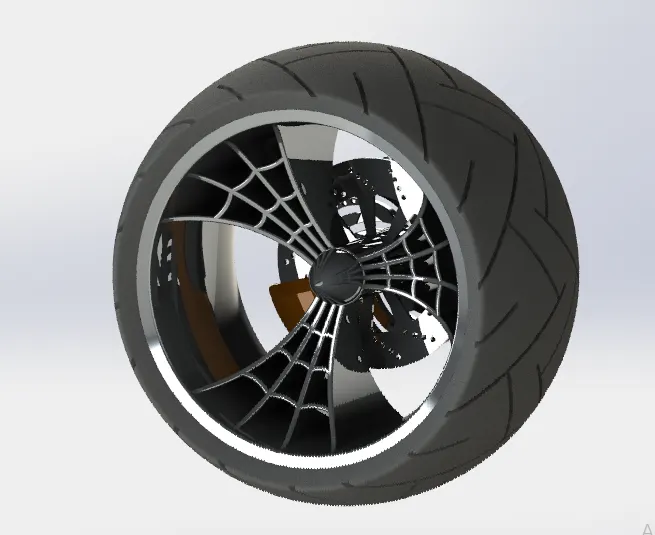
This is the wheel located in the back side of the chopper and is similar to front wheel except in some aspects.Rear wheel is connected with the engine transmission systems which drives the vehicle.
Commands Used In Modeling
Sketching: Circle,Line,Spline,3 Point Arc,Sketch Fillet,Extend Entities, Centre Point Rectangle,Trim
Features: Revolve,Extrude,Offset,Revolved Cut,Circular Pattern,Fillet,Chamfer
Appearance: Matte Rubber for Tyre,Chrome for Rim&Rotor,Siena for Caliper
Modeling Procedure:
- Modeling procedure is also similar the front wheel but an additional part i.e., sprocket is added to it.
- Rim was designed by creating the required sketch on the front plane and applying proper dimensions.
- The created sketch was used to create revolve and circular pattern.
- And spider web shaped spokes is designed and fillets were added and applied the proper appearance.
- Then design the caliper by drawing arc and using trim, extrude commands.
- Sprocket is drawn on the new plane offset fromt the mid plane using commands like circle,offset,and extruded cut and circular pattern.
- Finally tyre has been designed by drawing the required sketch on the front plane and revolved around the rim.
- Then Cuts on the tyres are drawn to provide grip for tyres as per instructed dimensions.
- Apply appearances for all the bodies appropriately.
J.Front Fork:
A motorcycle fork connects a motorcycle's front wheel and axle to its frame, typically via a yoke, also known as a triple clamp, which consists of an upper yoke joined to a lower yoke via a steering stem, a shaft that runs through the steering head, creating the steering axis. Most forks incorporate the front suspension and front brake, and allow the front wheel to rotate about the steering axis so that the bike may be steered. Most handlebars attach to the top clamp in various ways, while clip-on handlebars clamp to the fork tubes, either just above or just below the upper triple clamp.
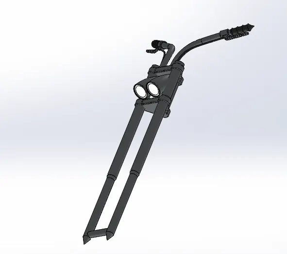
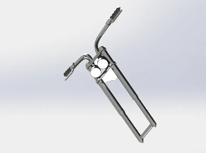
Commands Used In Modeling
Sketching: Circle,Line,Spline,Convert Entities,Trim
Features:Revolve, Extrude, ExtrudeCut, Offset, Curve, Revolved Cut, Dome, Project Curve, Sweep, Combine, Mirror, Fillet
Appearance: Chrome Steel – Fork, Matte Rubber – Handle Grip & Brake Wires.
Modeling Procedure:
- Draw a cylindrical diagram using line on the front plane and give relations to make it fully defined then revolve it.
- Then a draw a concentric circle to the fork tube on the top plane and draw another circle left and upward.
- And draw a horizontal construction line,spline and revolve it in the foent plane.Move the bulb in the z direction then fillet it.
- Select the top plane and draw a handle using spline, make it fully defined. From a circle at the end of the spline and sweep along the path.
K.Chasis:
A motorcycle’s chassis or frame forms its skeleton. All the components of a motorcycle, like the suspension, wheels, fuel tank, seats, handlebars etc, are attached to this base structure which lends a motorcycle its strength and ability to handle well. Motorcycle frames come in a variety of materials and shapes, based on the budgetary and performance-related limits of the end product.
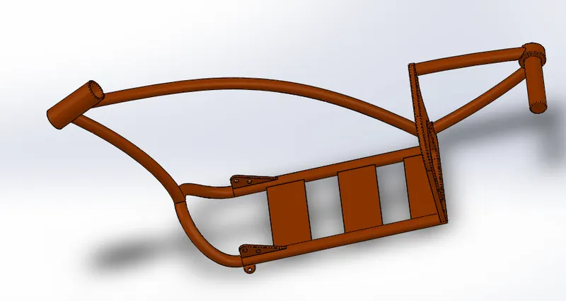
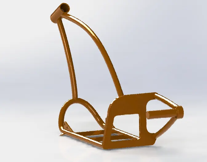
Commands Used In Modeling
Sketching: Line,Spline,Convert Entities,Trim,Offset, Circle,3 Point Arc
Features:Revolve, Extrude Cut, Project Curve, Sweep,Combine,Chamfer,Mirror,Fillet,Dome
Appearance: Painted Siena.
Modeling Procedure:
- Draw lines on the front plane as per the dimensions following the blueprint of the chopper imported.
- And draw another line from the top plane same as the front plane line and use projected curve option by selecting the two lines.
- Then a projected curve is created,similarly draw all the lines from using the blueprint and sweep by drawing a cicle on the perpendicular plane
- After drawing all the lines use fillets and combine command.
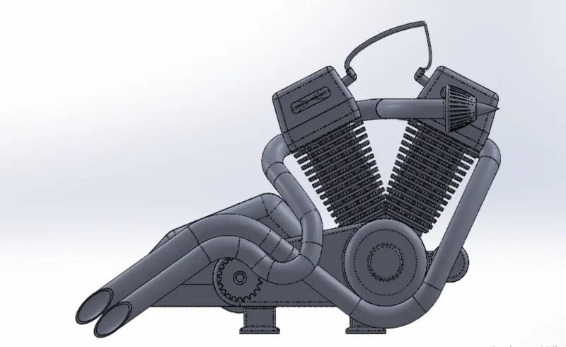
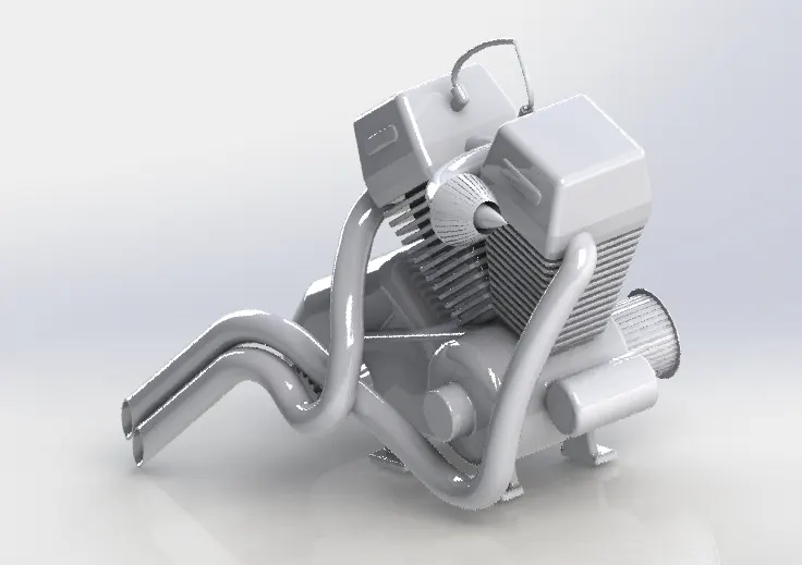
L.Engine:
A motorcycle engine is an engine that powers a motorcycle. Motorcycle engines are typically two-stroke or four-stroke internal combustion engines, but other engine types, such as Wankels and electric motors, have been used.
Most engines have a gearbox with up to six or even 7 ratios. Reverse gear is occasionally found on heavy tourers, for example the Honda GL1600, and sidecar motorcycles, such as the Ural. The rider changes gears on most motorcycles using a foot-pedal and manual clutch, but early models had hand-levers. More recently, some have automatic or semi-automatic gearboxes, and some using CVT transmission.
Commands Used In Modeling
Sketching: Line,Spline,Convert Entities,Circle,3 Point Arc
Features:Revolve, Extrude Cut, Sweep,Combine,Chamfer,Mirror,Fillet,Dome,Circular Pattern
Appearance: Chrome Steel
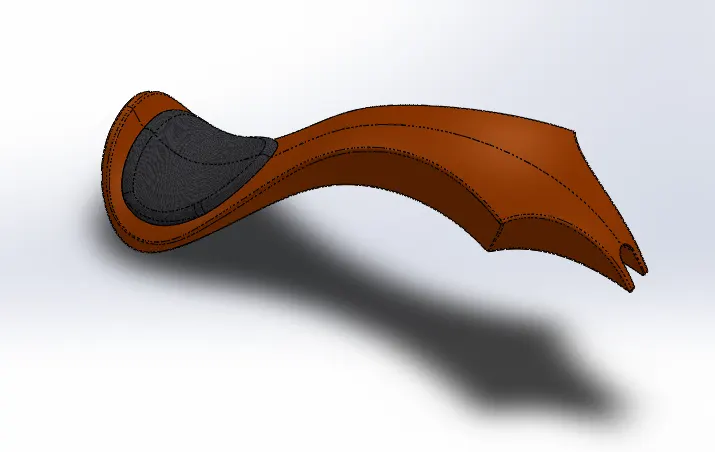
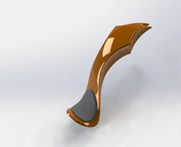
M.Gas Tank:
A fuel tank (also called a petrol tank or gas tank) is a safe container for flammable fluids. Though any storage tank for fuel may be so called, the term is typically applied to part of an engine system in which the fuel is stored and propelled (fuel pump) or released (pressurized gas) into an engine. Fuel tanks range in size and complexity from the small plastic tank of a butane lighter to the multi-chambered cryogenic Space Shuttle external tank.
Commands Used In Modeling
Sketching: Line,Spline,Convert Entities,Trim,Offset, Circle,3 Point Arc
Features: Knit, Swept, Loft,Revolve, Extrude Cut, Project Curve, Sweep, Combine, Chamfer, Mirror, Fillet, Dome, Boundary Surface, Shell
Appearance: Painted Siena – Gas Tank, Seat – Fabric
Modeling Procedure:
- Sketch on the front plane by drawing construction lines, spline roughly as per sketch picture and give dimensions to make it fully defined.
- Make a pierce relation with sketch then sweep surface from the plane drawn on the end point of the spline.
- Use extrude cut and project curve and combine commands appropriately as shown in the tutorial.
- Finally knit the surface and apply the appearances
2.Assembly:
There are two types of assemblies.They are i)Top Down Assembly
ii)Bottom Up Assembly
i)Top-Down assembly modeling :
Top-down assembly modeling is an assembly-centric modeling method where the assembly design is started at the highest level possible, and individual parts and subassemblies are defined within the context of the overall assembly. With this approach, an assembly layout is typically created first, and this assembly layout is used to define individual part geometry and position.
This approach is often used at companies where the product being designed is large enough that it requires many people to complete the design. A senior-level designer might create the initial assembly layout, then divide the assembly layout into logical subassemblies and parts for the remainder of the organization to complete.
ii)Bottom-Up assembly modeling :
Bottom-up assembly modeling is a part-centric modeling method where the assembly design is started with a principal structural or functional element, and individual parts are designed in relative isolation from the overall assembly. Component parts and subassemblies are defined as the process moves up towards the top-level assembly. With this approach, as the design of a key component is completed, its geometry may or may not be used to aid the design of related mating components.
In this chopper modeling we used bottom up approach.
Steps:
-Import all the modeled parts into the assembly module.
-Apply the mates as appropriate to the assembling part
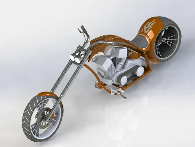
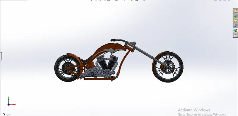
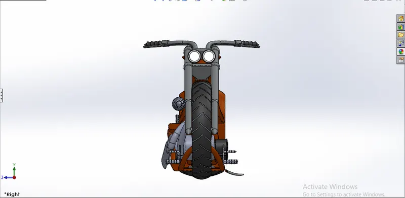
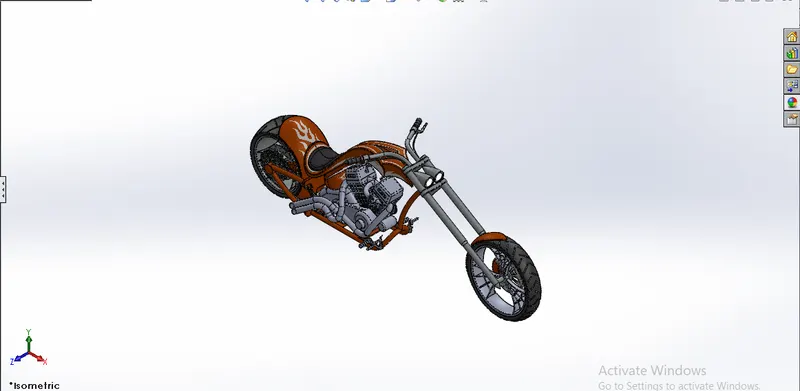
3.Rendering:
Decals: Apply the decals to the individual parts for the best appearance of the rendered image.
Photo View 360 : Then after applying decals, assembly is opened on the Photo view 360 tool which is an inbuilt tool in Solid works.
-Set the appropriate environment and background images and lighting to the model.
-Use camera views and adjust the brightness to make real looking image as possible.
-Finally check the preview of the image, if satisfied do Final Render and save the image.
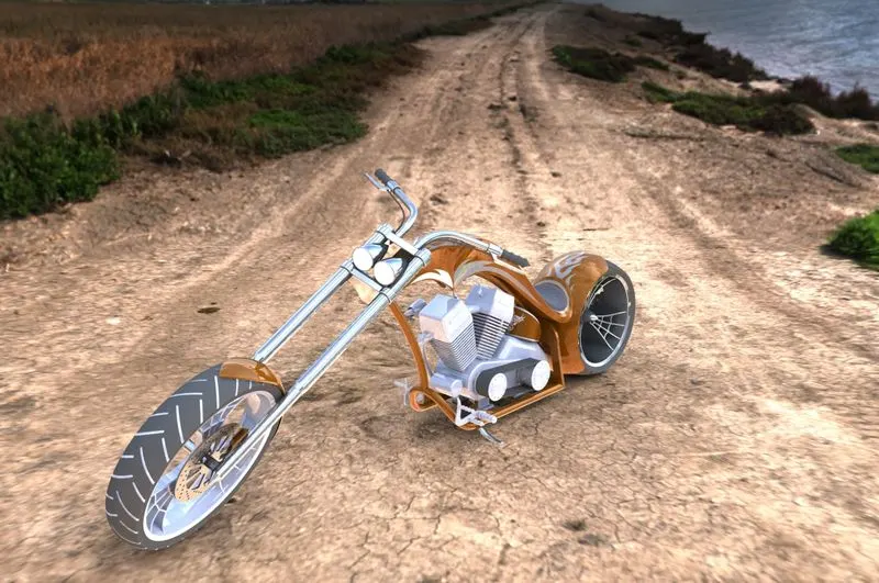
Camera View
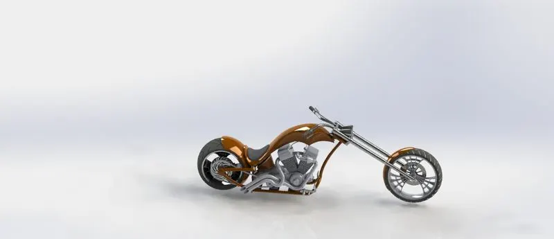
Right Side View
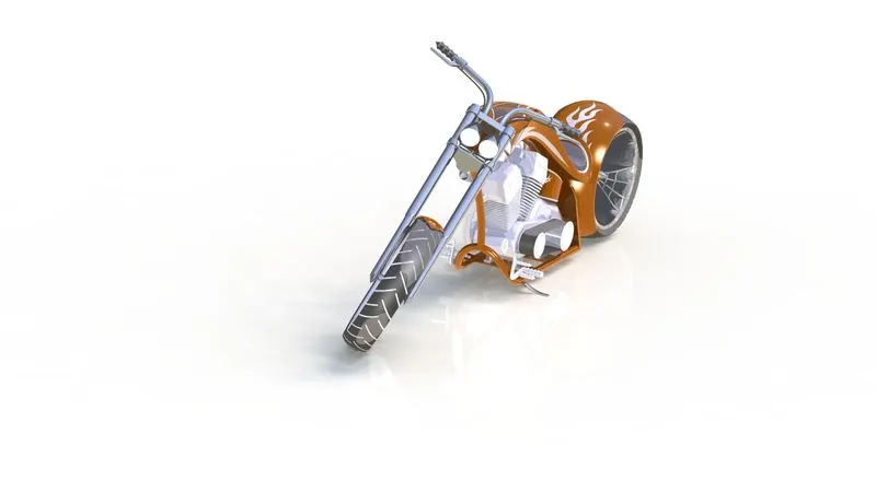
Front View
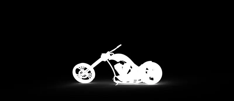
Alpha View
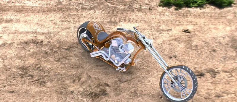
Isometric View
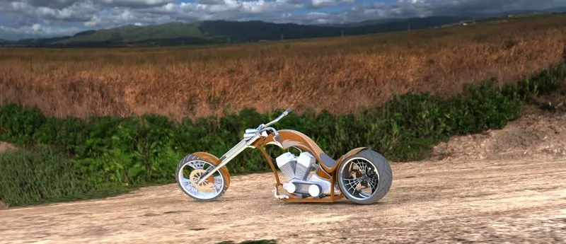
Side View Of American Chopper
Conclusion: Thus the design and assembly of American Chopper Motorcycle is completed in Solid Works and final rendering is done using Photo View 360 by applying all the appearances to make the model photo realistic.