Radar Mast & Final Assembly of Yacht
ASSEMBLY OF YACHT MODELLING
Aim :
- To model Radar mast and assemble the Yacht using SolidWorks.
Objective :
- To model a Yacht in SOLIDWORKS and Rendering it in Photo view 360 and SOLIDWORKS VISUALIZE.
Software used:
- SOLIDWORKS_2020 (Photo view 360 and SOLIDWORKS Visualize)
Introduction
- A yacht is any sail or power vessel used for pleasure, cruising, or racing. A yacht is any sail or power vessel used for pleasure, cruising, or racing.
- Yacht lengths normally range from 7 metres up to dozens of meters.
- A luxury craft smaller than 12 metres is more commonly called a cabin cruiser or simply a cruiser.
- The yacht modelled in this project is inspired by sunseeker.
Design Methodology :
- Setting of the blueprint for modelling of the yacht
- Solid and surface modelling of various parts of the yacht
- Assembly of the modelling parts of the yacht
- Rendering of the assemled yatch
The yacht modelling is carried out by modelling the individual parts separately as follows,
- Blue Print
- Propeller
- Rada
- Hull
- Garage door
- Front seat
- Middle seat
- Rear seat
- Superstructure
- Radar mast
- All these individual parts are modelled separately and assembled to form Yacht.
Procedure for modelling individual parts :
Blue Print
- A blueprint is a guide for making something or it's a design or pattern that can be followed.
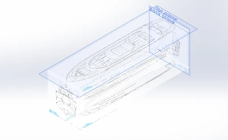
- Yacht blueprint is a combination of multiple images of the yacht, such as front view, top view, side view, bottom view and back view.
- Blueprint of the yacht is used for guidance while designing individual parts of the yacht.
Procedure for modelling Yacht blueprint :
- Open a new part and create a blueprint of the yacht.
- In a new sketch, import the image of the top view of the yacht and place it at an appropriate position with respect to the origin.
- Repeat the previous step to all the views such as- Front view, Side view, Bottom view and Back view.
- Save the file as the blueprint of the yacht.
- Rendered image of the yacht blueprint is shown below.
Image of the blue print :
Hull
- A hull is the major part of a ship or boat or yacht which is watertight in nature.
- It may be open at the top or may be fully or partially covered.
- Over the hull, there may be deckhouse, front seat, middle seat, back seat, mast, cabin etc.
- The line where the hull meets the water surface is called the waterline.
- A wooden floor is provided in the hull.
- Previously wood was used for constructing hull and nowadays most common construction material is fibreglass, followed by aluminium, steel, carbon fibre, and Ferro cement.
Features used to model the Hull:
- Sketch
- 3D Sketch
- Projected curves
- Offset entities
- Extrude surface
- Lofted surface
- Surface fill
- Trim surface
- Knit Surface
- Shell
- Boss Extrude
- Cut Extrude
- Extrude-Thin
- Cut-Extrude-Thin
- Fillet
- Chamfer
- Revolve
- Swept boss
- Helix
- Linear pattern
- Delete face
- Mirror
- Split Line
- Split
- Offset surface
- Appearance
Procedure for modelling Yacht hull:
- Insert the blueprint of the yacht in a new part.
- Create projected curves of the bottom part of the hull as per blueprint and create lofted surfaces.
- Create a lofted surface for the remaining bottom parts as per the blueprint.
- Trim unwanted surfaces for making the surfaces of the hull.
- Fill the open surface and knit all the surfaces.
- Create a shell of required thickness from the knitted surfaces.
- Create the deck surface by extruding.
- Create the basement by extruding.
- Remove unwanted portions from the hull model and provide fillet and chamfer to required edges.
- Create windows and portholes on the surface of the hull.
- Create stairs on the backside (one side) of the hull.
- Create long slots on the bottom surface of the hull.
- Provide fillet and chamfer to all the required edges.
- Create an anchor cable holder on the front side of the hull.
- Create windows on the surface of the hull.
- Create rail on the top of the hull.
- Create headlight on the front side of the hull.
- Create a shaft for the turbine on the bottom backside of the hull.
- Create a standing board on the front side of the hull.
- Create the remaining part of the hull by mirroring the hull modelled till the last step.
- Apply decals and appearance on the surfaces of the hull.
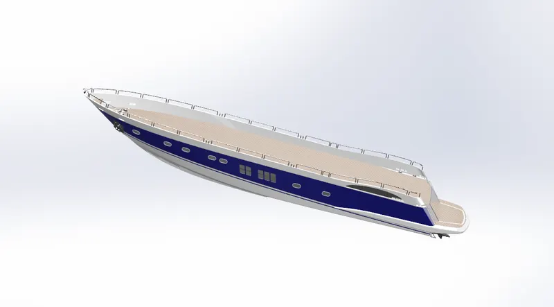
- Rendered images of the yacht hull are shown below.
Image of the part model :
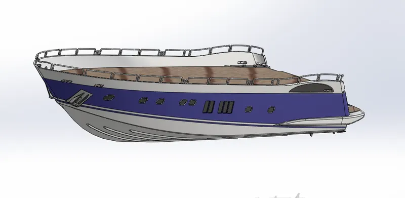
Image of the Rendering :
Radar
- Radar is a detection system that uses radio waves to determine the range, angle, or velocity of objects.
- It is used generally in aircraft, ship, spacecraft, missiles, weather formations etc.
- The radar consists of a transmitter, antenna for transmission, receiver and processor.
- The transmitter transmits a signal to the surroundings which are reflected back if there are any obstacles in its path.
- The reflected signal is received by the receiver and processed by the processor to find the type, size and distance of the obstacles.
- The radar used for the marine purpose is usually called as marine radars.
- It is used to detect other ships and land obstacles, to provide bearing and distance for collision avoidance and navigation at sea.
- Rotating antenna is used for wide coverage while the ship is in motion.
Features used to model the Radar:
- Sketch
- Boss Extrude
- Fillet
- Cut extrude
- Sketch pattern
- Mirror
- Split Line
- Appearance
Procedure for modelling Yacht radar :
- Insert the blueprint of the yacht in a new part.
- Create the side view of the radar and extrude it.
- Provide fillet to all the sharp edges.
- Create the cap and fasteners on the side of the radar.
- Create the remaining part of the radar by mirroring the hull modelled till the last step.
- Apply decals and appearance on the surface of the radar.
- Rendered images of the yacht radar are shown below.
Image of the part model :
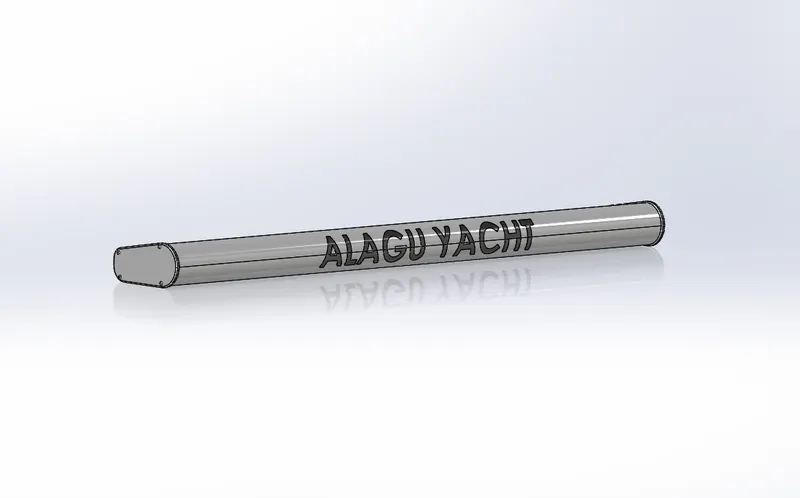
Image of the Rendering :
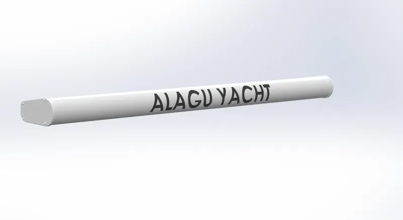
Radar mast
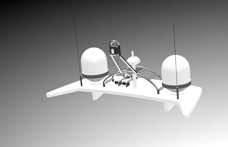
- Radar mast is the mounting device of the radar in the ship.
- It is usually placed above superstructure.
- It has an appropriate position for keeping all the radar related equipment such as a transmitter, receiver, processor etc.
- Air horns are also fixed in radar mast.
Features used to model the Radar mast:
- Insert Part
- Sketch
- Boss extrude
- Revolve
- Swept
- Mirror
- Projected Curve
- Shell
- Fillet
- Dome
- Mirror
- Fillet
- Appearance
Procedure for modelling Yacht radar mast :
- Insert the blueprint of the yacht in a new part.
- Create the bottom plate of the radar and provide fillet to all the sharp edges.
- Create the cylindrical tank on the bottom plate.
- Provide fillet and chamfer to all the required edges.
- Create an antenna starting from the bottom plate.
- Create radar holder and light holder.
- Create two horns on the top of the bottom plate of radar mast.
- Create the remaining part of the radar mast by mirroring the part modelled till the last step.
- Apply appropriate colours to all the required surfaces.
- Rendered images of the yacht radar mast are shown below.
Image of the part model :
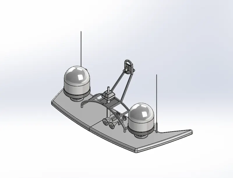
Image of the Rendering :
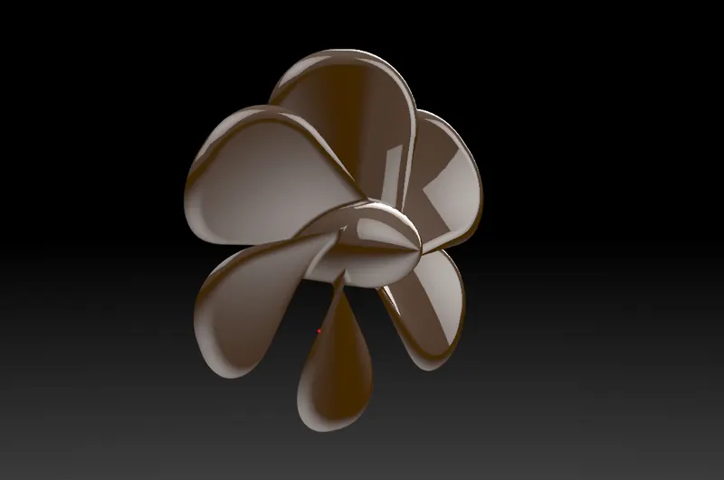
Propeller
- A propeller is a type of fan that transmits power by converting rotational motion into thrust.
- A pressure difference is produced between the forward and rear surfaces of the airfoil-shaped blades, and a fluid (such as air or water) is accelerated by the pressure difference.
- Most marine propellers are screw propellers with helical blades rotating around an approximately horizontal axis or propeller shaft.
- Six blades are used on the propeller used in this model.
Features used to model the propeller:
- Sketch
- Revolve
- Surface Loft
- Fillet
- Circular pattern
- Cut extrude
- Appearance
Procedure for modelling Yacht propeller :
- Insert the blueprint of the yacht in a new part.
- Create the centre shaft of the propeller.
- Create one propeller blade and provide fillets to all the necessary edges.
- Create a circular pattern of the propeller blade throughout the shaft at equal distance.
- Apply colour to the surface of the propeller.
- Rendered images of the yacht propeller are shown below.
Image of the part model :
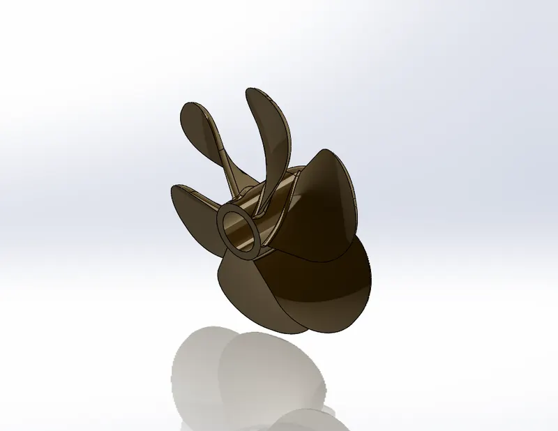
Image of the Rendering :
Garage door
- A garage is the storage space provided in the yacht for parking personal vehicles such as car, motorcycles etc.
- In this yacht, an American chopper is placed inside the garage.
- The garage is closed by using a door which is usually called a garage door.
- The garage door is usually made of wood or metals.
Features used to model the Garage door :
- Cut Extrude
- Shell
- Fillet
- Mirror
- Reference plane
- Appearance
Procedure for modelling Yacht garage door :
- Insert the blueprint of the yacht in a new part.
- Insert a block from the hull, which is removed from the hull for creating a garage for parking of a private vehicle in the hull.
- Remove all the unwanted portion of the block inserted and provide fillet on all the required edges.
- Create the remaining part of the garage door by mirroring the garage door modelled till the last step.
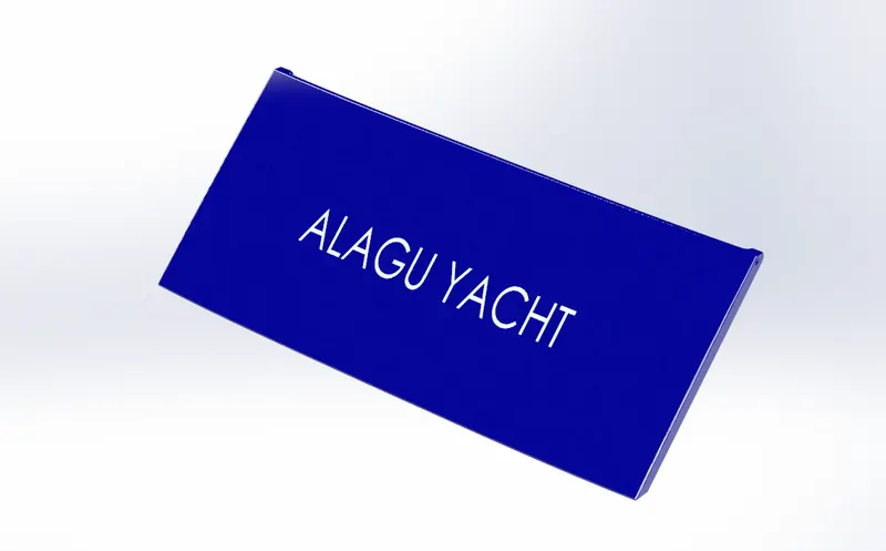
- Create the name of the yacht on the surface of the garage door.
- Apply colour to the surface of the door.
- Rendered images of the yacht garage door are shown below.
Image of the part model :
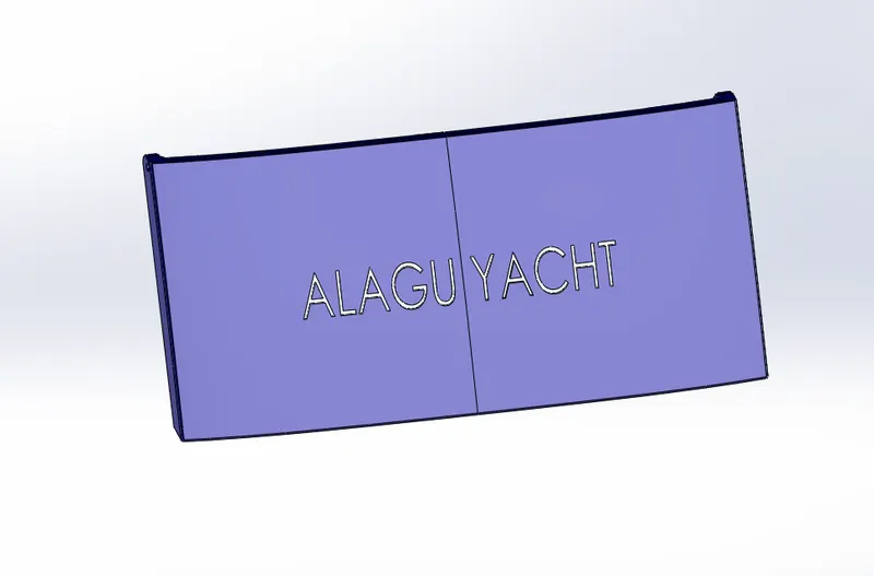
Image of the Rendering :
Yacht seats
- Seats used in the yacht are of different types and forms.
- Seats with nice cushions are usually used in yachts.
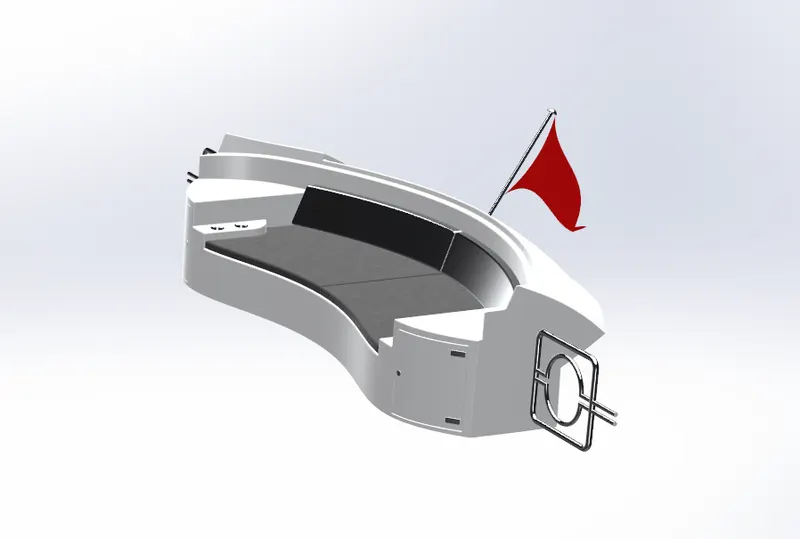
- Three types of seats are used in this project- Front seat,
- Middle seat and Rear seat.
- Front seat is kept in the front portion of the hull and it has a seating capacity for 3-4 persons.
- The middle seat is kept just behind superstructure.
- The middle seat consists of a table and chairs and has a seating capacity for 5 persons.
- The rear seat is kept at the rear end of the hull.
- The rear seat has a seating capacity of 2 to 3 persons.
- The rear seat has a wooden cupboard and teacup holder as an additional feature.
Front seat
Features used to model the Front Seats:
- Insert Part
- Sketch
- Reference plane
- Surface Sweep
- Surface Trim
- Surface Loft
- Knit Surface
- Surface Fill
- Chamfer
- Revolve
- Cut extrude
- Fillet
- Dome
- Mirror
- Appearance
Procedure for modelling Yacht Front seat :
- Insert the blueprint of the yacht in a new part.
- Create a projected portion in the side of the front seat of the yacht on the floor of the hull using surface modelling.
- Create the seating portion of the front seat.
- Provide fillet and chamfer to all the required edges.
- Create additional cushion on the surface of the seat.
- Provide fillet and chamfer to all the required edges.
- Create the remaining part of the front seat by mirroring the seat modelled till the last step.
- Apply appropriate colours to all the required surfaces.
- Rendered images of the yacht front seat are shown below.
Image of the part model :
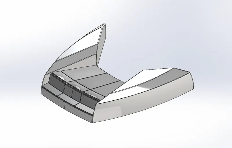
Image of the Rendering :
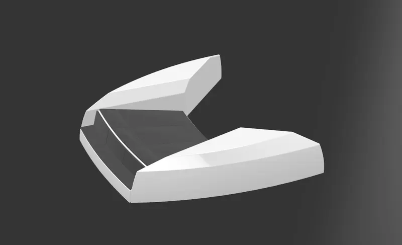
Middle seat
Features used to model the Middle Seats :
- Insert Part
- Sketch
- Boss Extrude
- Chamfer
- Fillet
- Cut Extrude
- Mirror
- Appearance
Procedure for modelling Yacht Middle seat :
- Insert the blueprint of the yacht in a new part.
- Create the base of the middle seat.
- Create the seating portion above the base the seat.
- Create the cushioning part of the seat above the seating portion.
- Provide fillet and chamfer to all the required edges.
- Create the remaining part of the middle seat by mirroring the seat modelled till the last step.
- Create table at the centre of the middle seat.
- Apply colour to all the required surfaces.
- Rendered images of the yacht middle seat are shown below.
Image of the part model :
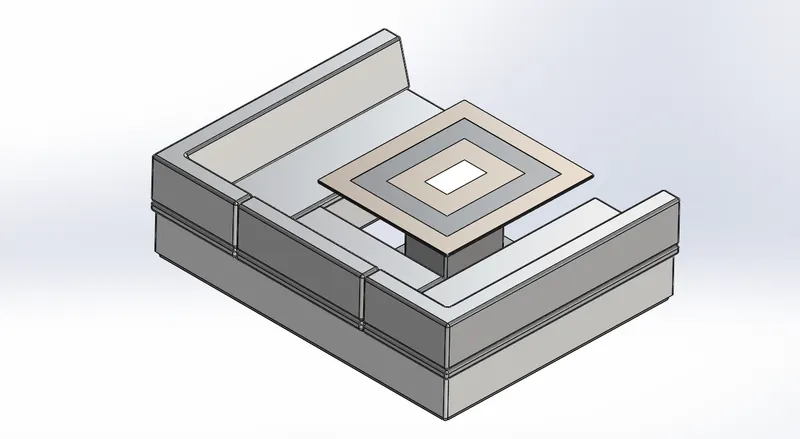
Image of the Rendering :
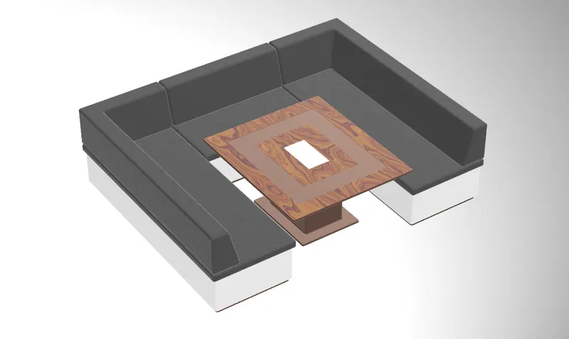
Rear seat
Features used to model the rear Seats:
- Insert part
- Sketch
- 3D Sketch
- Reference plane
- Surface Sweep
- Surface Offset
- Surface Trim
- Ruled Surface
- Surface Knit
- Surface Extrude
- Surface Extend
- Boss Extrude
- Cut Extrude
- Sweep
- Revolve
- Fillet
- Chamfer
- Mirror
- Appearance
Procedure for modelling Yacht Rear seat :
- Insert the blueprint of the yacht in a new part.
- Create a rear portion of the rear seat of the yacht on the floor of the hull using surface modelling.
- Create the basement of the rear seat.
- Provide fillet and chamfer to all the required edges.
- Create a hand rest portion on the side of the rear seat.
- Create a cup holder beside the hand rest.
- Create additional cushion on the surface of the seat.
- Provide fillet and chamfer to all the required edges.
- Create a cub board below the hand rest portion.
- Create a gate on one side of the rear seat.
- Create the remaining part of the rear seat by mirroring the seat modelled till the last step.
- Create a flag holder and flag above the rear portion of the rear seat.
- Apply appropriate colours to all the required surfaces.
- Rendered images of the yacht rear seat are shown below.
Image of the part model :
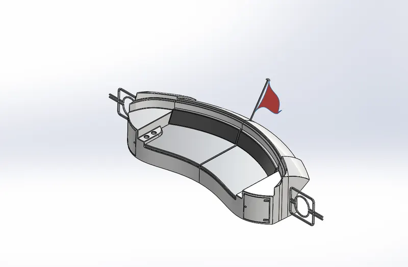
Image of the Rendering :
Superstructure
- A superstructure is an upward extension of an existing structure above a baseline.
- The superstructure is a ship/ yacht is the part that emerges from the deck.
- In this yacht superstructures like the front seat, middle seat, rear seat and cabin are modelled.
- The superstructure may be built in multiple layers.
- In this yacht single layer superstructures are used.
- Space for living accommodation, meeting room etc.
- provided inside superstructures.
Features used to model the Superstructure :
- Insert part
- Sketch
- 3D Sketch
- Reference Plane
- Surface Sweep
- Surface Extrude
- Loft Surface
- Filled Surface
- Ruled Surface
- Extend Surface
- Trim Surface
- Surface Knit
- Offset surface
- Projected Curve
- Boss Extrude
- Cut Extrude
- Extrude-Thin
- Thicken
- Sweep
- Fillet
- Chamfer
- Dome
- Delete face
- Split Line
- Appearance
Procedure for modelling Yacht Superstructure :
- Insert the blueprint of the yacht in a new part.
- Create half of the superstructure by surface modelling and convert it into a solid body.
- Create a foundation tank on the front side of the superstructure.
- Provide handle for on the surface of the foundation tank.
- Create steps in the front portion of superstructure.
- Create glass window portion on the surface of the superstructure.
- Create a wiper part over the front window.
- Create a handle for the backside door of the superstructure.
- Create a surface on the foundation tank and provide appropriate transparency on it.
- Apply colour to all the necessary surfaces.
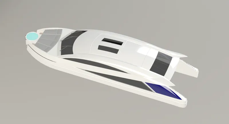
- Rendered images of the yacht superstructure are shown below.
Image of the part model :
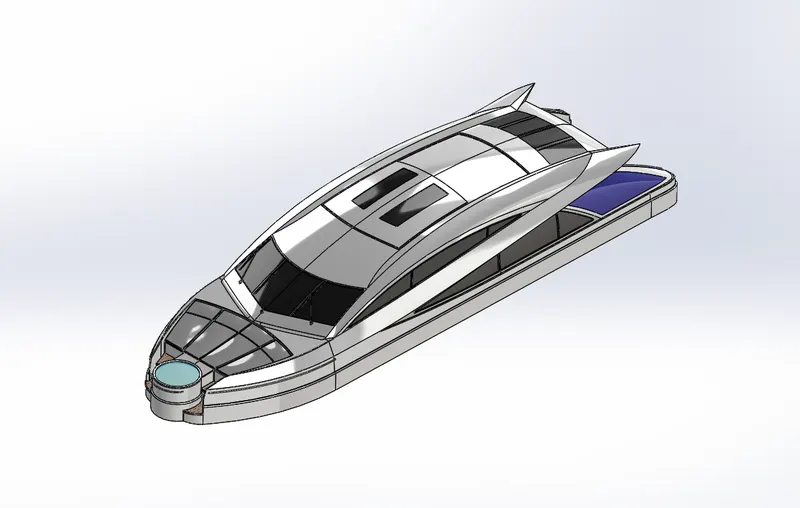
Image of the Rendering :
ASSEMBLY OF THE YACHT
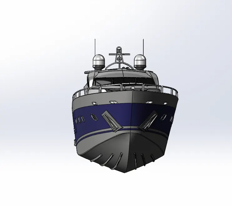
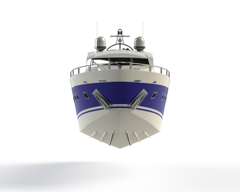
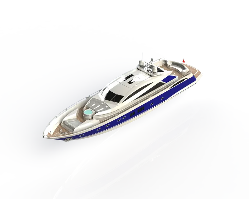
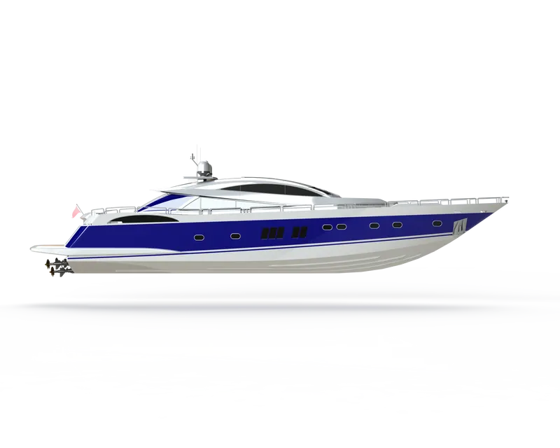
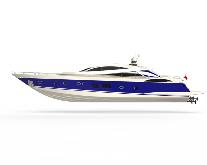
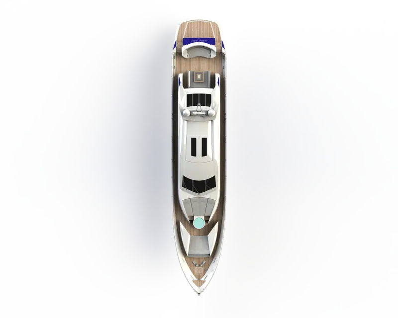
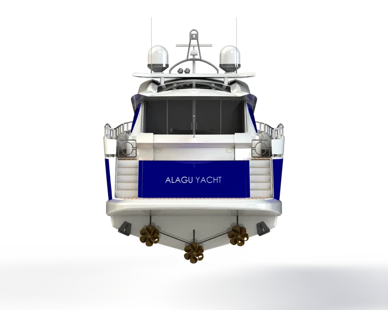
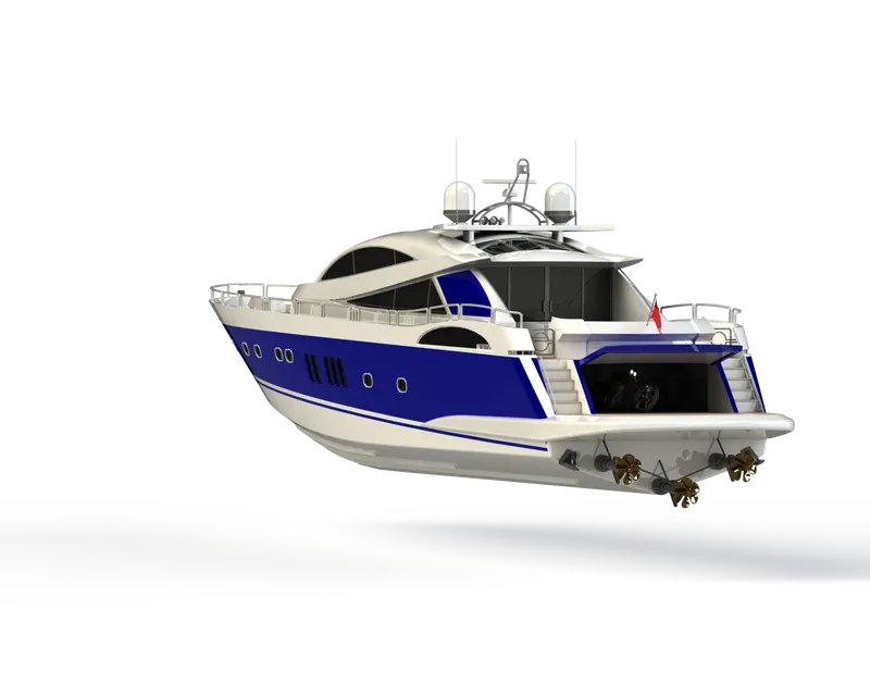
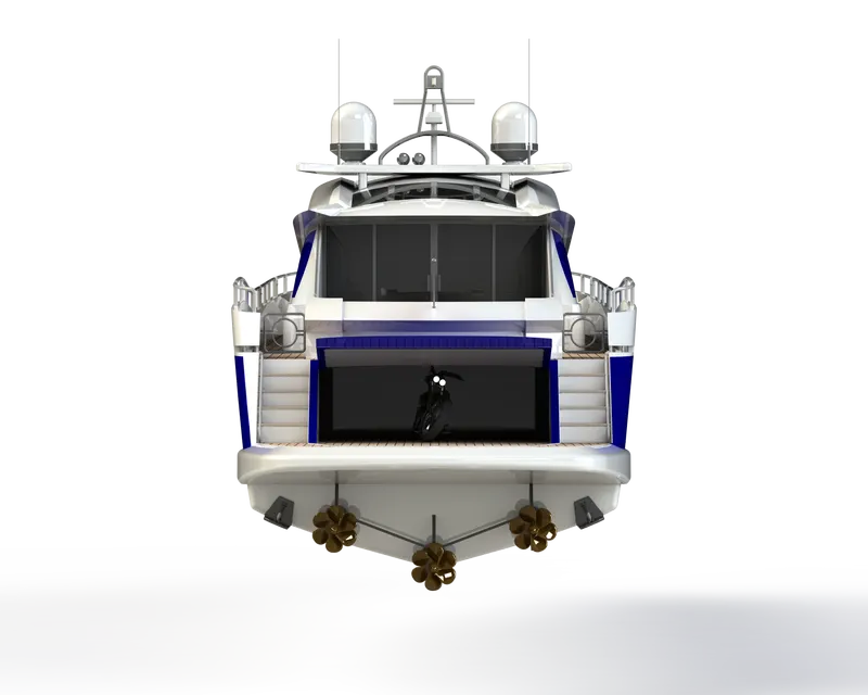
- The individual components of the yacht are assembled together to have the fully modeled yacht.
- The process begins by bringing Hull to the assembly environment and aligning the planes of the Hull with that of the planes in the assembly environment to make sure it is constrained.
- Then all the other parts are opened and made constrained by mating the face, planes, and circular cross-section of the Hull to the individual part with the help of the mating feature.
- Since many parts of the yacht are modeled with hull deck as a reference it becomes easy to assemble those parts as it takes up the position correctly.
Features used in Assembly of the Yacht:
Mates
- This feature is used to constraint any two parts by adding a geometric relationship between the two parts.
- There are many options like tangency, concentric distance, etc to choose from which would constrain one part with respect to another.
- There are also advance mate options like width mate, Angle mate, etc which would help to add more practicality to the assembled model.
Insert Parts
- This feature is handy to add different parts that are needed to be assembled into the assembly environment.
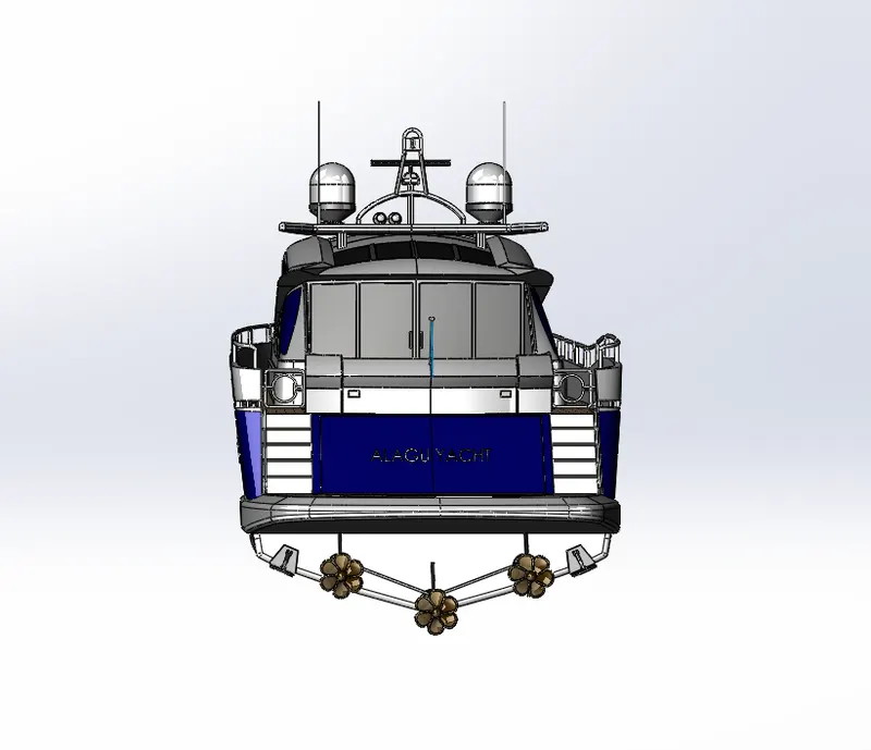
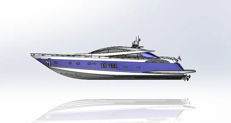
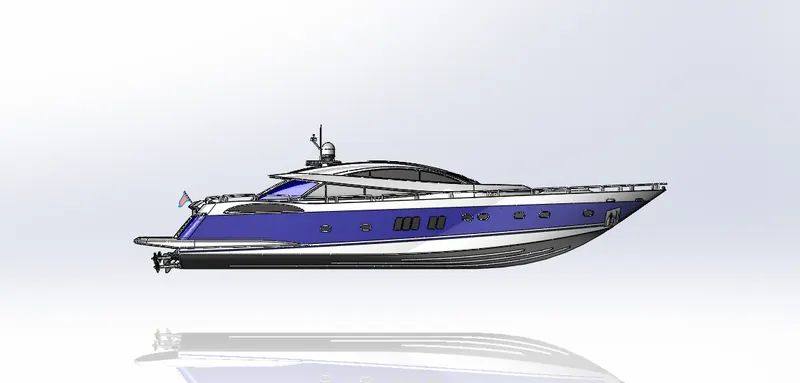
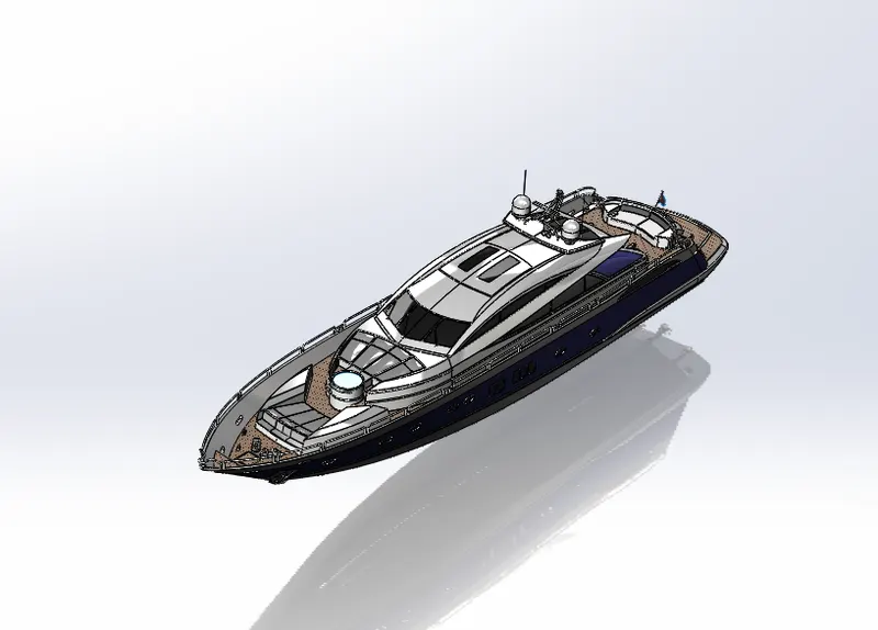
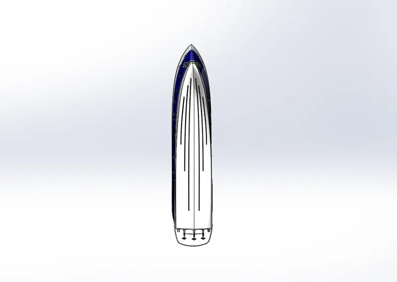
Images of the assembled yacht :
Front view
Back view
Right side view
Left side view
Isometric view
Bottom view
Top view
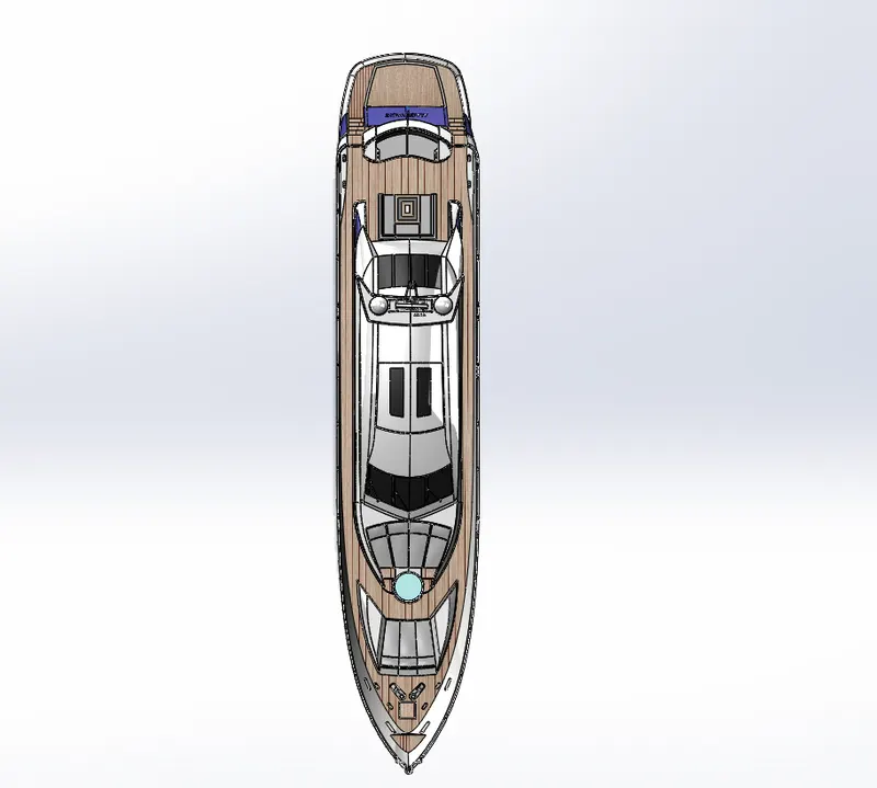
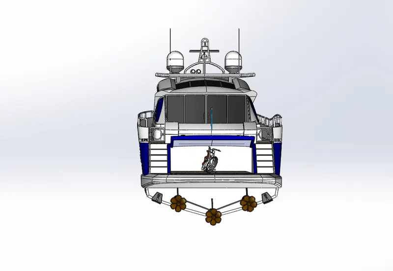
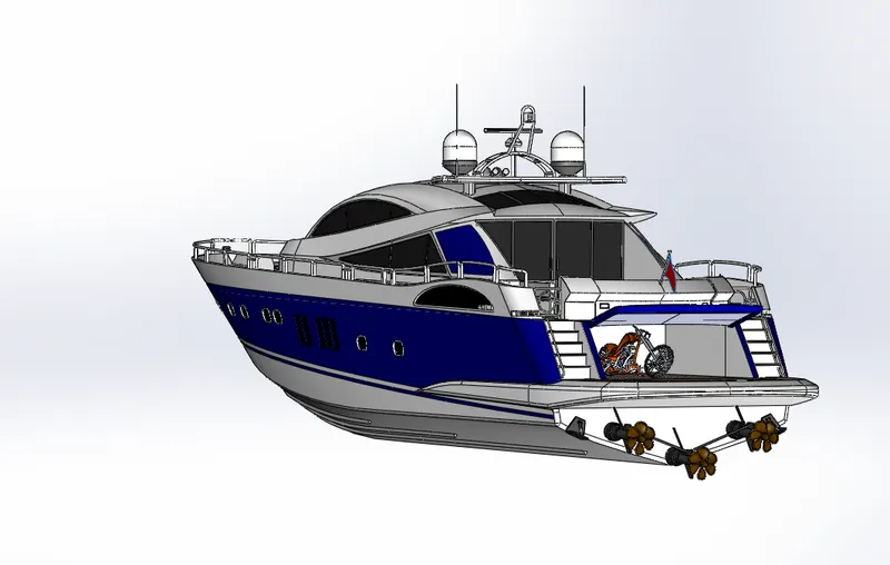
Photo 360 image :
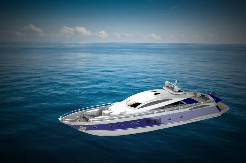
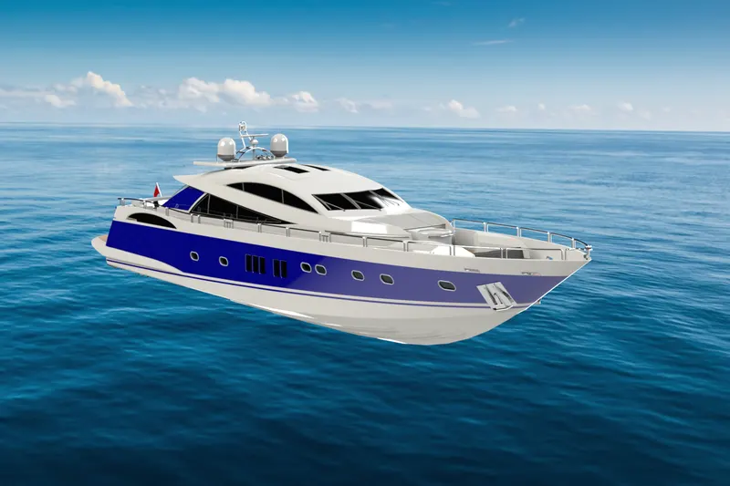
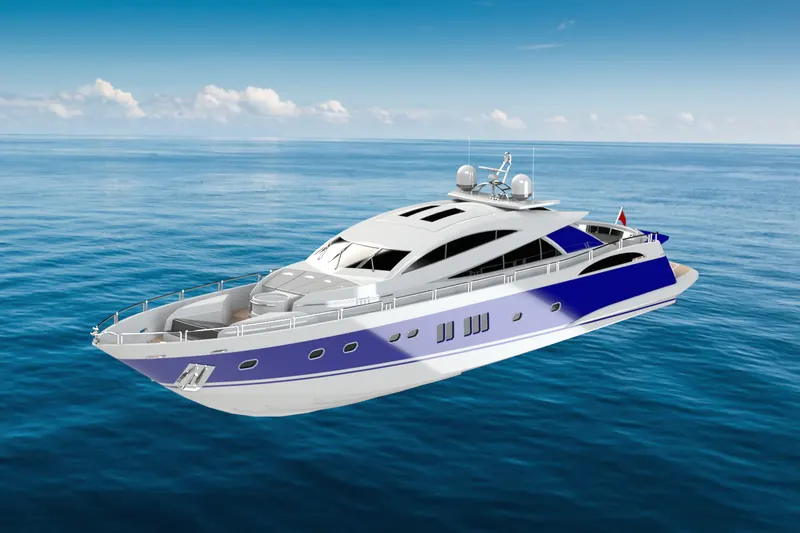
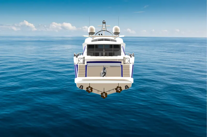
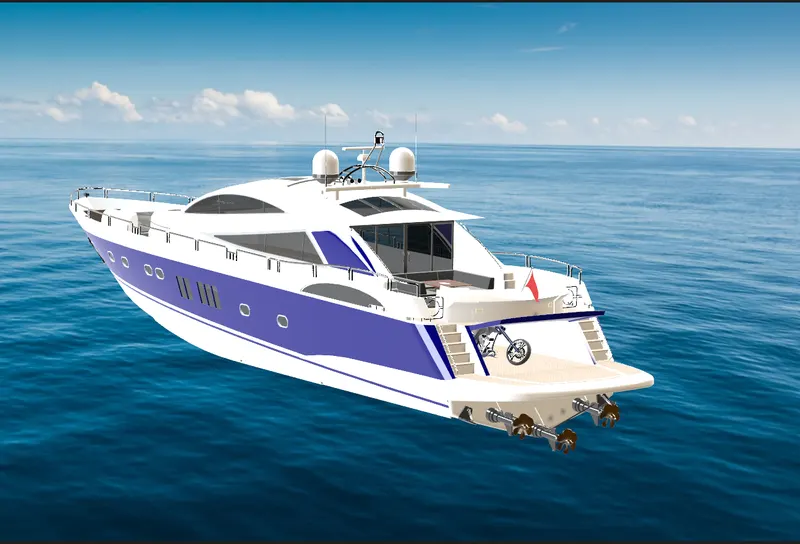
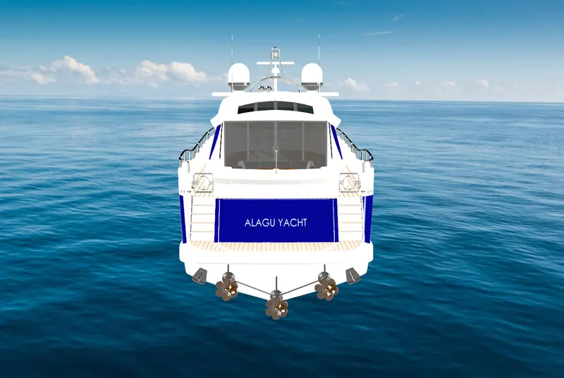
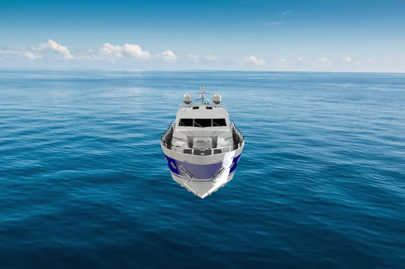
Rendering of the model of Yacht in SOLIDWORK visualize :
- SOLIDWORKS VISUALIZE is the software used for rendering any model created in the SolidWorks.
- In this HDR environment, lighting conditions, camera position, etc. can be changed for getting rendering images.
Image of the Rendering :
Google drive link :
https://drive.google.com/drive/folders/1GQh2YSXs8mzFGx7dFS9vDP1J2tmVnnUE?usp=sharing
CONCLUSION
- Hence, the various parts of the yacht were modeled using part and surface modeling, assembled and photorealistic renders were created.