Radar Mast & Final Assembly of Yacht
Title: Design of Sunseeker Yatch.
Objective:
The objective of this project is to learn and understand the different tools and commands in SolidWorks by creating a Model of the Sunseeker Yatch with all the different parts and to assemble the different parts in the assembly. Finally to Render and make a photorealistic view in the SolidWorks Visualize and PhotoView 360.
Introduction:
In this project we use Solidworks 2020 software to design an Sunseeker Yatch and the complete procedure of creating parts and the assembly is explained in this report.
Features of Solidworks used in this project are:
BASIC FEATURES:
- Sketch: A collection of lines and other 2D objects/entities on a plane or face that forms the basis for a feature such as a base or a boss. A 3D sketch is non-planar and can be used to guide a sweep or loft.
- Offset: It is a feature in sketching features, wherein an entity can be placed away from the original entity at a certain distance.
- Extrude: A feature that projects a sketch to either add material to a part (in a base or boss) or remove material from a part (in a cut or hole).
- Fillet: Fillet creates a rounded internal or external face on the part. You can fillet all edges of a face, selected sets of faces, selected edges, or edge loops. Fillet can have single radius throughout or it can have multiple radii.
- Chamfer: A cut on the edge or corner of something that makes it slope slightly rather than being perfectly square. It can either be symmetric or asymmetric.
- Loft: Loft creates a feature by making transitions between profiles. A loft can be a base, boss, cut, or surface. You create a loft using two or more profiles. Only the first, last, or first and last profiles can be points. All sketch entities, including guide curves and profiles, can be contained in a single 3D sketch.
- Dome: Select one or more faces. You can apply domes to faces whose centroid lies outside the face. This allows you to apply domes to irregularly shaped contours. Dome can be elliptical or spherical.
- Split: The Split tool is used to project an entity (sketch, solid, surface, face, plane, or surface spline) onto other surfaces or curved/planar faces. You are also able to split faces on multiple bodies with one command.
- Trim Entities: Select the trim type based on the entities you want to trim or extend. All trim types are available with 2D sketches and 2D sketches on 3D planes.
- Revolve: This feature makes a solid body or surface which has circular symmetry around an axis.
- Dynamic Mirror: Dynamic mirror is an important tool in solid works. As you sketch the entities, they can be mirrored about the pre-selected sketch entity with this tool.
- Appearances: An appearance defines the visual properties of a model, including color and texture. Appearances do not affect physical properties, which are defined by materials.
- Combine: Combine is the type of feature available in solid works to manually combine the two bodies which intersect each other.
- Shell: The shell feature helps create thick, thin, or composite shells from solid bodies. This feature can also create shell which is offset from the solid body.
- Circular Pattern: The circular parent bodies/ features are used to create a different number of instances of the required feature to create the pattern circularly.
- Linear Pattern: In linear pattern parent bodies/ features are used to create a different number of instances required to create the pattern linearly along a pre-selected direction.
SURFACE MODELING:
- Surface modeling gives you the ability to build out a visual representation of an object’s exterior and its contours. In other words, it’s a surface.
- Parts like hull, superstructure, front and rear seat of Sunseeker Yatch are surface modeled.
Features Description:
- Lofted Surface: Loft Surfaces are surfaces generated by multiple 3D Curves or existing edges creating a smooth tangency between the selected curves.
- Swept Surfaces: Swept Surfaces are surfaces that are generated from a section curve positioned along a path.
- Filled Surface: The Filled Surface feature constructs a surface patch with any number of sides, within a boundary defined by existing model edges, sketches, or curves, including composite curves.
- Surface Trim: Primarily used to cut away material from a surface, and provides two modes: Standard and Mutual.
- Extend Surface: Extend Surface is used to extend the surface which is already created. There are different options available on the extended surface. We can extend the surface as same surface or we can extend the surface tangent to the surface.
- Surface Knit: Surface knitis used to knit the two free edges/open edges of the surfaces together. Also it reduces the gap between the two edges of the surface
PARTS MODELED FOR SUNSEEKER YATCH:
The parts of the Sunseeker Yatch are modeled in Solidworks and assembled together are as follows:
- Blueprint
- Front seat
- Garage door
- Hull
- Middle seat
- Propeller
- Radar mast
- Radar
- Rear seat
- Superstructure
Design Methodology
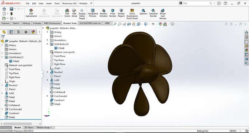
Propeller
Features used to make Propeller are:
- Revolve
- Loft
- Fillet
- Circular pattern
- Cut extrude
- Fillet
- Combine
|
Start Solidworks and select new part, save as propeller |
|
Create Shaft of propeller with help of revolve. |
|
Now create one wing of propeller with help of loft feature by creating two skew rectangular sketches on different planes |
|
With the help of fillet tool make the edges rounder in shape of the letter D, again round the edges of wing with fillet. |
|
With help of circular pattern create 5 more wings around the centre shaft |
|
Cut extrude to hollow out the shaft of the propeller |
|
Fillet the edges where the wings meet the shaft of propeller and combine the solids with the help of combine feature. |
Radar
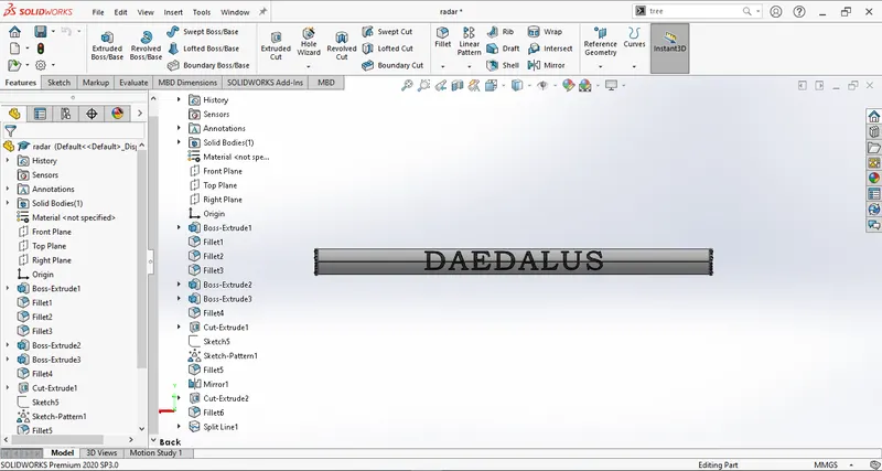
Features used to make Radar are:
- Extrude
- Fillet
- Cut extrude
- Mirror
- Split line
|
Open solidworks and create a new part, Save as radar |
|
Create a prismatic extrude of the shape of the cross-section of the radar |
|
Mirror the extrude about the surface of extrude where there is no flange |
|
Create a blind hole in the centre of the body of the part in its middle with cut extrude tool. |
|
Apply fillet to the edges of the extrude |
|
Make a flange on one end of the extrude with the help of offset sketch feature and extrude to off-set sketch. Make 4 screw heads on this flange with help of extrude, fillet, cut extrude and linear pattern. |
|
Create logo on radar with the help of sketch and split line feature |
Blueprint setup
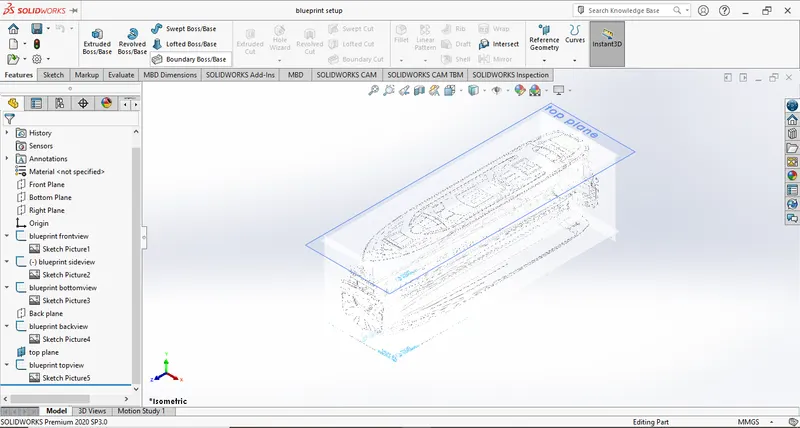
Features used to make the setup are:
- Reference features: planes
- Sketch entities: sketch pictures
|
Open solidworks, create a new part, save as blueprint setup |
|
Make appropriate reference planes and create sketch on them |
|
Add appropriate blueprint photos to corresponding view planes |
Hull
Features used to create Hull are:
- Surface loft
- Surface trim
- Surface extrude
- Surface knit
- Surface fill
- Shell
- Boss extrude
- Cut extrude
- Fillet
- Chamfer
- Sweep
- Revolve
- Dome
- Helix/spiral
- Linear pattern
- Delete face
- Extrude thin
- mirror
- Split line
- Offset surface
- Mirror
|
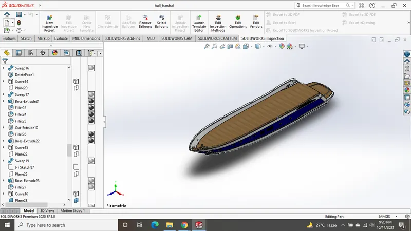
Open solidworks and open blueprint setup.sldprt file, rename the file as hull. |
|
Sketch on two planes the same edge of the hull as shown in the blueprint sketch image and combine these sketches by using projected curve to get the edge in 3D. Use this method to get other edges |
|
Use surface loft feature to generate required surfaces |
|
Use surface trim to trim the extra surfaces, at last generate surface extrude to cover all the surfaces. Trim away the extra surfaces using surface trim |
|
Now use Surface knit to combine the surfaces and generate a solid body |
|
Use surface fill to cover the top face |
|
Using shell feature create a solid shell of required thickness |
|
Use boss extrude feature to generate the deck of the hull |
|
Use boss extrude, chamfer and fillet took to create the rear lower deck |
|
Use cut extrude to cut the extra shell generated on the rear of the hull |
|
Use cut extrude, fillet, linear pattern and sweep features to create glass window impressions on the surface of the hull |
|
Create through holes on hull above the deck with cut extrude and pad them with sweep feature |
|
To create stairs from upper deck to rear lower deck first cut extrude feature was used and then boss extrude feature was used to create the stairs |
|
With the help of boss extrude and offset from surface option we create ridges are created on the bottom surface we use appropriate chamfer and fillet to it to create the required shape. |
|
Add remaining features to the deck using extrude, cut extrude, helix/spiral and linear pattern features. |
|
Create railings on hull and near the stairs using the sweep feature. |
|
Make a platform on the bow of the boat using boss extrude. |
|
Using cut extrude create appropriate cavity for garage. Again cut extrude to create solid cut out save this solid as garage_door.sldprt. Now create a pin for attaching garage door on the hull. |
|
Use boss extrude to create a platform for connecting buoy. Make the buoy using boss extrude, chamfer, fillet and mirror features |
|
Use revolve feature to create fixture where propeller is to be fitted and then use extrude to make oars on it and thin extrude to attach the oars to hull. Next use linear pattern feature to make similar solid feature in the center of the yatch. Use cut extrude to cut away excess soild from the resultant feature. |
|
On the rear of the hull below the deck we create a fixture to attach a stabilizer with extrude, fillet, cut extrude and revolve features |
|
Use split line feature to create stripe surface on the hull outer surface. Apply appropriate appearances to the hull |
|
Mirror the solid we generated about the middle plane |
Garage door
Features used to create garage door are:
- Cut extrude
- Shell
- Fillet
- Mirror
|
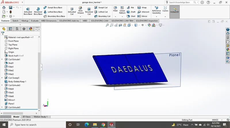
Open garage_door.sldprt in Solidworks |
|
With Cut extrude cut appropriate thickness of the door from the cutout. |
|
Use fillet on the appropriate edges of appropriate radii |
|
Use shell feature to get required geometry on the inside of the garage door |
|
Mirror the resultant geometry about the middle plane |
Front seat
Feature used to create the front seat are:
- Surface sweep
- Surface extrude
- Surface trim
- Surface fill
- Surface loft
- Surface knit
- Chamfer
- Revolve
- Cut extrude
- Mirror
- Dome
- Fillet
- Boss extrude
- Chamfer
- Fillet
- Mirror
|
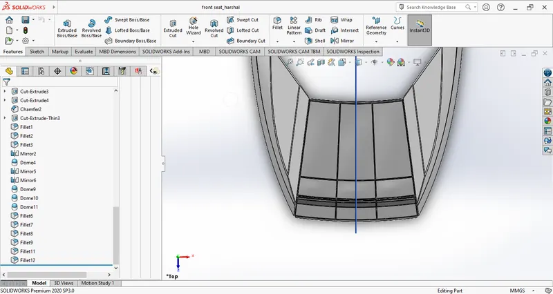
Open blueprint setup.sldprt in Solidworks and save it as front_seat |
|
Seating area is made using Revolve feature, appropriate fillets are provided wherever necessary |
|
The two outer bodies which are shaped as wings are surface modeled with the help of surface sweep, surface extrude, surface trim, surface fill, surface knit and chamfer |
|
Insert>part>hull.sldprt supress solid body except for the deck surface |
|
Mirror bodies is used to mirror the resulting geometries about the middle plane |
|
Domes are provided on the solids to give an organic look. Appropriate appearances are applied to the seat |
Middle seat
Features used to create middle seat are:
|
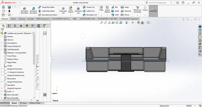
Open blueprint setup.sldprt in Solidworks and save it as middle_seat |
|
Insert>part>hull.sldprt supress solid body except for the deck surface |
|
The base of the seating area is made using boss extrude and fillets are applied to the edges |
|
Center table is made using boss extrude, fillet and the top embossing is made with cut extrude. Appropriate appearances are applied to the part. |
|
The backrest and cushions are made using boss extrude, chamfer and fillet |
Rear seat
Features used to make front seat are:
- Surface sweep
- Surface offset
- Surface trim
- Ruled surface
- Surface knit
- Surface extend
- Surface extrude
- Surface loft
- Boss extrude
- Cut extrude
- Chamfer
- Fillet
- Sweep
- Mirror
- Revolve
|
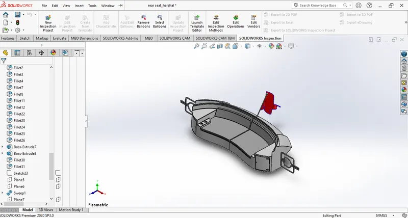
Open blueprint setup.sldprt in Solidworks and save it as middle_seat |
|
Insert>part>hull.sldprt supress solid body except for the deck surface |
|
The base and back rest are first surface modeled using surface sweep, offset, trim, knit extend extrude and loft and ruled surface. The resultant surface geometry is made into solid with ‘try form solid’ option in surface knit |
|
The seating area is made with boss extrude |
|
We add fillet to the sharp edges around the part created |
|
We make cushions using extrude and chamfer and provide fillets to them |
|
Drawer is made using cut extrude cupholders are made on the base using boss extrude and cut extrude |
|
Side railings are created using sweep tool and then we use mirror tool to mirror the generated solid about middle plane. |
|
Flag on the rear seat was created using surface loft feature. We apply appearances to the part. |
Superstructure
Features used to create the superstructure are:
- Surface extrude
- Surface sweep
- Surface knit
- Ruled surface
- Surface trim
- Surface loft
- Fillet
- Surface extend
- Boss extrude
- Cut extrude
- Surface fil
- Cut extrude>Thicke
- Dome
- Fillet
- Sweep
- Revolve
- Mirror
- Surface offset
- Chamfer
- Cut loft
- Body delete/keep
|
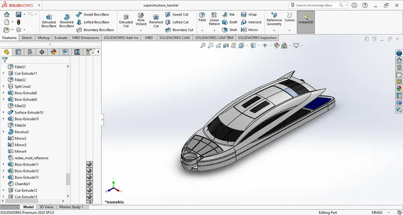
The external surfaces of the superstructure are surface modeled using surface extrude, surface sweep, surface knit, ruled surface, surface trim Surface loft, fillet and surface extend |
|
Open blueprint setup.sldprt in Solidworks and save it as superstructure.sldprt |
|
Insert>part>hull.sldprt supress solid body except for the deck surface |
|
Jacuzzi is made using boss extrude, fillet and cut extrude (to get half of the jacuzzi) |
|
The stairs near Jacuzzi are made using surface extrude, surface trim, surface extend, surface sweep and surface knit |
|
The surface coveting the mid plane is generated using surface extrude and trimmed according to surface geometry using surface trim to get a closed surface body where hdeck surface is covering the lower portion. |
|
We hide the deck surface of the hull and add a surface using surface extrude and surface trim to cover the lower open portion |
|
Details are added to the superstructue such as panels near the jacuzzi, the rear doors, the front glass panels, the sun roof and the windshield wipers, we add fillets to any sharp edges on the generated surface body. Save the surface where radar mast is to be fixed after forming new surface by surface offset. |
|
Now we make the railings near the jacuzzi and the rear portion of superstructure using sweep. |
|
We use surface knit to knit this lower surface to the surface body and create solid cody by checking’try forn solid’. |
|
Use mirror body to generate whole body and apply appropriate appearances to the outer surfaces. |
Radar mast
Features use to create radar mast are:
- Boss extrude
- fillet
- Sweep
- Revolve
- Mirror
- Chamfer
- Dome
|
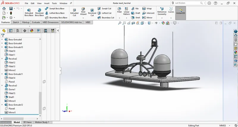
Open blueprint setup.sldprt in Solidworks and save it as radar mast.sldprt |
|
Insert>part>superstructure.sldprt supress solid body except for the the surface where mast is to be made |
|
The base of the radar mast is made using boss extrude and fillet |
|
The railings are made using sweep |
|
The antenna is made using boss extrude and fillet |
|
The receiver of the radar mast is made using revolve and fillet |
|
The radar post is made using boss extrude, fillet and chamfer |
|
The supporting base pillar is made using boss extrude and fillet |
|
The body generated is mirrored about mid plane and we create horns using revolve, dome fillet and mirror |
|
Appropriate appearances are applied to the part. |
Assembly
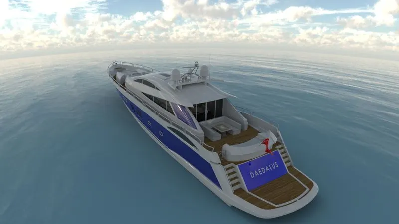
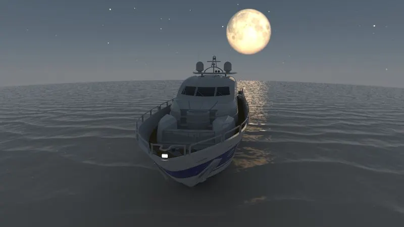
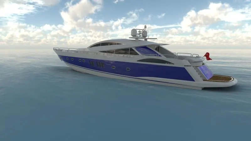
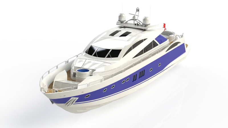
All the parts are assembled in their appropriate positions.
We get the assembly.