Radar Mast & Final Assembly of Yacht
REPORT ON YACHT
PART MODELLING,ASSEMBLY AND RENDERING OF YACHT
OBJECTIVE:
The objective of this project to create a 3D model of the yacht by using Solidworks 360.While creating this model we undergo part,design and Assembly of all these parts and rendering the created Assembly by Rendering tool is to give a realistic touch to our model by using the software Solidworks 360.
INTRODUCTION:
Solidworks 360 is 3D designing Software which is capable of different function to create a 3D model of our liking.In this software there a lot of feature to make our model look realistic we use rendering features.As being a multi platform for our creation of Yacht model we use this software for creating model.
In this Yacht model we are undergoing the part creation and using the render tools for making it realistic appearance.During the modeling of the Yacht we will make the most of the use of surface modeling and make them to use our individual structured required for the Yacht model which will led us to design the required different yacht parts.After we will use those parts to render and give a realistic appearance by using the render tools in Solidworks.
DESIGN METHODOLOGY:
To create a Yacht we have to undergo three pases or steps as shown
- Yacht Model
- Individual part creation of the structure of Yacht
- Assembly of Parts to create Yacht Model
- Rendering and application Realistics features
Modelling of Yacht
To create this yacht model it is different from the any other model,In this we will not concentrate on the inner detailing we will be concentrating on the outer surface which are visible to us.We divided them into different parts structure and undergo part modeling.After that creation we will be using these parts and making them as the refrence for the other part by this we will saved of time for mating each other is Assembly.After that we use render tools for the realistic features and we use Solidworks visualize for more accurancy.
CREATION OF PARTS AND ASSEMBLY OF THE YACHT:
In the creation of yacht model the first step is to create the different parts of the Yacht model by using Solidworks 360.Before creating the different parts we have to know the different tools and features which are available for the part creation of the project.We have listed some different tools and features,Surface features etc are listed below,which we have used for the part creation.
SKETCH TOOLS:
In the sketch tool bar there is a sketch icon which allow us to create a 2D sketch on the selected plane or selected surface or selected point.
LINE:
Line tool is used to create a line between any points and from this tool,we can create different types of line like construction line,Midpoint line etc
RECTANGLE:
This tool is used to create a rectangle in the sketch plane and we can draw the rectangle in different ways like center pont,by sides,by diagonal length three point rectangle and parallelogram.
SLOT:
This tool is used to create slot which is created by using the center the distance and radius of the slot and there are other options for creating arc slot also
CIRCLE:
This tool is used to create a circle by using the radius length and there is an option for the creation of perimeter circle.
ARC:
This tool is used to create an arc by the radius and also by using the sides and also by use three points.
POLYGON:
This tool is used to create a polygon by defining the inner circle and the no of sides and the angle between the sides in the sketch plane.
SPLINE:
This tool is used to create a curve driven by points between any two points are surfaces and we can create the curve without any uniformity.
ELLIPSE:
This tool is used to create a ellipse based on the major and minor radius and in this tool,they are other options where we can create half ellipseetc
SKETCH FILLET:
This tool is used to create rounded corners called as fillet by selecting the corners or the intersection of lines and by entering the radius values.
SKETCH CHAMFER:
This tool is used to create inclined edges by selecting the angles and the distance at the required lines on the sketch.
POINT:
This tool is created to create a point on the sketch plane to create a refrence for our diagram as required applications.
TRIM ENTITIES:
This tool is used to trim or to cut the entities which are intersecting and unwanted lines by selecting by using power trim in the sketch plane.
CONVERT ENTITIES:
This tool is used to concert the boundaries of any 3D boundary in to lines for which we can take as refrence for creating the sketch.
EXTEND ENTITIES:
This tool is used to extend any line or arc to other line meeting arc by selecting extending entity and the boundary of the entity.
MIRROR ENTITIES:
This tool is used to mirror the sketch by selecting the mirroring entities and after that selecting the line with which respective they have to mirrored.
OFFSET ENTITIES:
This tool is used to offset the required entities or sketch part or sketch lines to be copied inward or outward of the selected entities to the required distance.
LINEAR SKETCH PATTERN:
This tool is used to create a copy of the sketch in form of a pattern in linear fashion along the selected direction in the sketch.
CIRCULAR SKETCH PATTERN:
This tool is used to create a copy of sketch in circular pattern at an equal intervals of angles in the sketch plane.
3D FEATURES:
EXTRUDE/BOSS/BASE:
This is a tool used to convert a 2D closed sketch to a 3D solid by giving the height distance of extrude.
REVOLVE/BOSS/BASE:
This is a tool used to create a revolved solid by convert a closed sketch and revolving with respective an axis or plane.
SWEPT/BOSS/BASE:
This tool is used to create a sweep hollow solid by creating a closed sketch and creating a closed profile along the curve which is selected.
LOFT/BOSS/BASE:
This tool is used to create a solid body which has a curve guide through two different closed of two cross section and areas.
EXTRUDE CUT:
This tool is used to cut or make hole or remove the unwanted surface from a solid body by created a closed profile on the required surface or plane of solid.
REVOLVE CUT:
This tool is used to cut a closed sketch profile in revolved manner with respective to the given axis or line removing required material from the solid.
MIRROR ENTITIES:
This tool is used to create a mirrored solid of the same dimensions with refrence to the plane or the surface of the body.
LINEAR PATTERN:
This toolis used to create a linear pattern of solid or cut in solid material in a linear fashion by selecting the number of copies and the offset distance between the selected body or cut solid.
CIRCULAR PATTERN:
This tool is used to create a circular pattern of copies by selecting a refrence a circle from which it would create copies at intervals of angles according to the design.
FILLET/CHAMFER:
This tool is used to create a rounded surface by giving the radius to the selected edges of the solid.
DRAFT:
This is used to create a chamfer between two different area profile combine by inclined way to create a solid.
REFRENCE PLANE:
This is used to create a new plane by taking the refrence of different points,lines and curves according to the requirement.
PROJECTION CURVE:
This is used to create a one single curve which is formed by combining to different curves having a joining points but situated in two different planes resulting in smooth curve passing from both plane.
COMPOSITE CURVE:
This curve is combination of two different projection curve to create a one final composite curve which can pass through the two projection curves.
SPLIT:
This is used to remove or split or cut the unwanted parts or solid bodies intersecting each other to result a perfect one solid body.
COMBINE:
This tool is used to create a combined solid body by two different solid bodies to get a one body enhanced by the two solids.
3D SKETCH:
This tool is used to create a 3D sketch by giving the dimension in 3D system.
SURFACE FEATURES:
EXTRUDE SURFACE:
This tool is used to create an extruded surface by creating a closed profile in the choosen direction of required thickness.
REVOLVE SURFACE:
This tool is used to create a revolved surface of specified thickness with respective to the axis
SWEPT SURFACE:
This tool is used to create a swept surface along the guided profile or curve with the required thickness of the surface.
TRIM SURFACE:
This tool is used to trim the unwanted surface for the profile by selecting the specified surface which is to be removed.
KNIT SURFACE:
This tool is used to combine two surfaces as a single body or surface by knitting and make the both surface boundaries coincident and tangent to one another.
MIRROR SURFACE:
This tool is used to create a mirrored surface of the same surface with respective to the selected plane and selected boundary of the surface.
FILLET:
This tool is used to create a rounded corner by selecting edges of the surface and giving them the required surfaces.
BOUNDARY SURFACES:
This tool is used to create a surface which are connected and going through the different boundaries by taking the refrence of the edges.
EXTEND SURFACE:
This tool is used to create the surface to extend surface normal and tangent proportion by using different boundary condition.
SPLIT SURFACES:
This tool is used to split the surface and is used to create another model which we can save in different part model.
LOFTED SURFACE:
This tool is used to create a surface by using the refrence of two guide lines and profile curve.
FILLED SURFACE:
This tool is used to create a surface by filling the space of closed boundary sketch by creating a surface.
DELETE SURFACE:
This tool is used to delete face which we select.It is also a repair option in which it will delete and add the face by applying tangent proportion to the created surface.
RULED SURFACE:
This tool is used to create a surface based on different properties.By this we can create the surface perpendicular and tangent to the vector by determining the angle of tilt.
OFFSET SURFACE:
This tool is ued to create an offset the selected surface which will divide them with the orginal surface.These are some of the most common tool used in creating our parts required for Yacht we divided this yacht model into a different parts first before creating this model we have to note these points.
- We have to see the units are correctly set to millimeters,If no we have to set it by clicking on the right hand corner of the workspace.
- The every tool,features,solid body appearance and surface we use is updated in the feature tree we can edit and see the feature in this tree.
- If we draw any sketch we have to give the perfect dimension such that the sketch is full defined other wise it will rearrange itself if accidentally snap those under defined it would change the profile sketch,so we have to be carefully in defining the elements.
- We does not have to overdefine the sketch profile such that it will error and we cannot change it to any required solid body,This can been seen in the feature tree beside the sketches solid as symbol.
- We have to careful in giving the relations between any elements in the sketches we have to refrence it to the orgin by keeping these in mind we began to create the parts of the Yacht as described below.
DESCRIPTION:
While designing first we have to identity the component or sub assembly of the Yacht to get the final model assembly,splitting component of a model before designing provides the scope of improvement and avoid lengthy modeling.
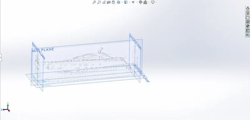
BLUEPRINT SETUP:
It is used as a guide for sketching and designing models.Before modeling each part,a blue print setup is to be done in a part file.Sketch image of the Yacht is to be added to the different plane as per view.It helps to draw and design model easily.
COMPONENTS OF YACHT:
- Radar
- Propeller
- Hull
- Garage
- Front seat
- Middle seat
- Rear seat
- Superstructure
- Radar mast
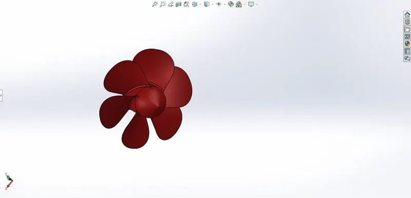
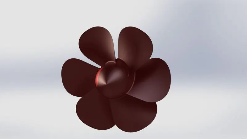
PROPELLER:
- The first step is to create a 2D sketch on the midplane and revolve it as to create a solidbody by using revolve Boss/Base
- After that create an another sketch on the topplane and after that create another plane which is away from the top plane at distance of 360mm and create a sketch as shown in fig
- After that create a lofted body from the two sketches on the different planes and make the guide curve on the same side.
- Add the required fillet to the edges of the lofted body and make the lofted to create a circular pattern and also cut extrude a hole,propeller is created.
RADAR:
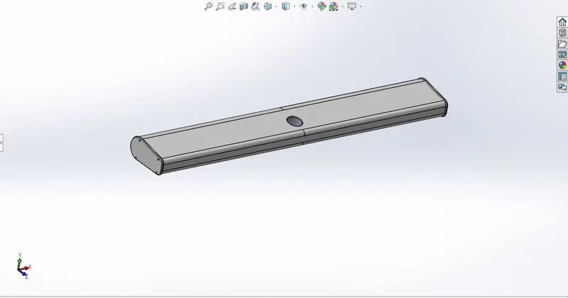
In this part we create a 2D sketch which is used to create an extrude boss base.
Radar is a detection system that use radio waves to determine the range,angle or velocity of objects.It can be used to detect aircraft,Ships,spacecraft,guide missiles,motor vehicles,weather information and terrain.
COMMAND USED:
- Line
- Circle
- Text
- Point
- Extrude Boss Base
- Fillet
- Mirror
- Split
- Line
MODELLING PROCEDURE:
- The part has symmetric geometry so first create a symmetric portion.
- Boss features(parent) created by drawing sketch and extruded boss features
- Additional features(child) added like cap and bolt by using extrude boss and extrude cut.
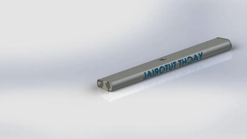
- The radar has a circular slot underneath which has created using extrude cut.This is very important while assembly to make the part properly
- Filet is applied to the edges of the body and finally save the model by applying appearance.
HULL:
A hull is the waterlight body of a ship or boat.The hull may open at the top or be fully or partially converted with a deck.A top the deck may be a deck house and other superstructure such as funnel,derrick or mart.The line where the hull meets the water surface is called the waterline.
COMMAND USED:
SKETCH COMMAND USED:
- Line
- Circle
- Spline
- Rectangle
- Ellipse
- Straight slot
- Arc
- Convert
- Offset entities
- Trim entities
- 3D sketch
FEATURE COMMAND USED:
- Extrude boss
- Revolve Boss
- Swept boss
- Extrude cut
- Fillet
- Chamfer
- Linear pattern
- Circular pattern
- Shell
- Mirror
- Split
- Delete/keep body and save Bodies.
SURFACE COMMAND USED:
- Extrude surface
- Revolved surface
- Swept surface
- Lofted surface
- Boundary surface
- Filled surface
- Offset surface
- Ruled surface
- Delete face
- Extend surface
- Trim surface
- Knit surface
- Thicken
MODELLING PROCEDURE:
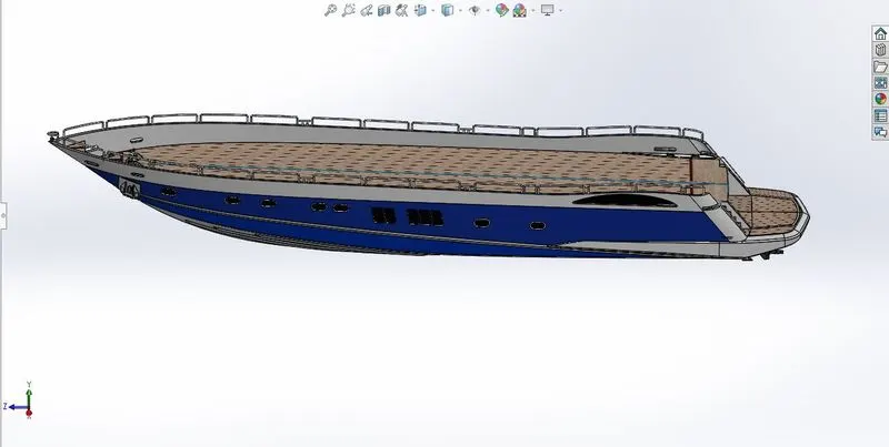
- First open the blue print setup file and save it by the name Hull.
- The Hull of the Yacht looks symmetric in geometry.It provides flexibility to create a half model then mirror it about the plane or middle face of the Yacht.
- Main body:Draw sketches to create two 3D curves by using the project curve option.
- Create three outer surfaces of the Hull using Loft surface.Extrude surface and trim unnecessary portion using Trim surface combine three surface create surface by using Knit surface.
- Fill the surface on the top side and right side to make a closed model using fill surface with edges of outside surfaces.
- Knit all surfaces to combine and select create solid to form a solid model.
- Use the shell to make a deck for other components.
- Windows: use refrence sketch,extrude cut ,plane,swept boss,fillet.
- Stair:Extrude cut,extrude boss,fillet.
- Railing:Plane refrence sketch,project curve,swept boss,delete a face fillet.
- Garage: Extrude cut,extrude boss,fillet,save bodies.
- Propeller Assembly:Revolved boss,extrude boss and cut,linear pattern,chamfer,fillet.
- Some additional features were added to the hull to get a good appearance.
- After modeling the half portion of the hull mirror it along a mid pane or middle face of the hull.
- Create a surface by using the offset surface on the deck and hide it.This surface will use for modeling superstructure,Front seat,Middle seat and Rear seat.
- Apply decal to floor,stair.Apply appearance to model and save it.
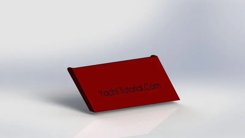
GARAGE DOOR:
A garage door is a large door on a garage that opens
Either manually or by an electric motor(a garage door opener)
Garage door are frequently large enough to accommodate automobile and other vehicle.
COMMAND USED:
- Extrude Boss
- Extrude cut
- Shell
- Plane
- Mirror
- Fillet
- Text
MODELLING PROCEDURE:
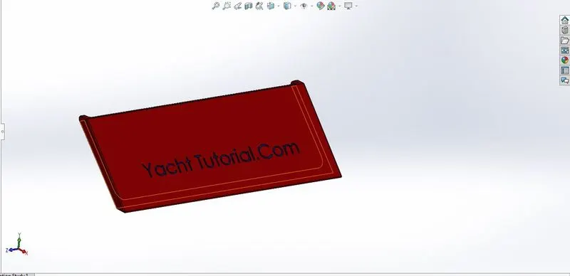
- The garage door needs to be model in an important model from the hull by cut extrude feature to get identical dimension and proper fitting.
- The door is also an asymmetric body,so first modal half portion and then mirror it about the plane.
- The shell features is used to thin the thickness of the door.
- Cut extrude is used to add the cut hole for mating in assembly.
- Fillet added to get a smooth appearance.
- Apply the appearance and save the model.
FRONT SEAT:
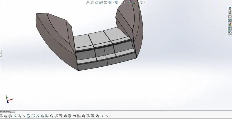
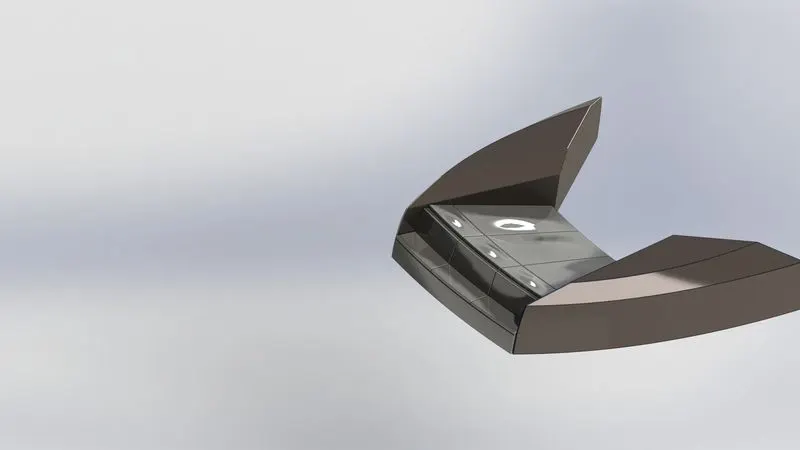
Front seat is located at the front end of hull which is usually used for seating and to enjoy the scenery.
COMMAND USED:
- Swept surface
- Loft surface
- Filled surface
- Extrude surface
- Trim surface
- Knit surface
- Revolve Boss
- Extrude cut
- Fillet
- Chamfer
- Mirror
- Dome
MODELLING PROCEDURE:
- Open the blue print setup file and save it by name Front Seat
- Insert the hull part by selecting the surface bodies.
- Create swept surface by creating a sketch on Deck face by drawing a spline and another sketch on a created plane by drawing a line.
- Draw two lines and connect with previously created surface sweep and extrude the surface.
- Trim the extra surface and fill the gap portion with a filled surface.
- Draw few sketch according to trim extra surface.
- Create surface loft using the above two sketches.
- Trim the extra surfaces and knit them together.
- Draw lines according to create the seat and revolve it about 10 degrees.
- Apply fillet and mirror the bodies
- Finally apply dome to seat and give the appearance.
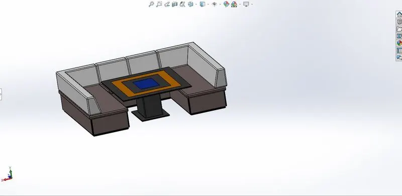
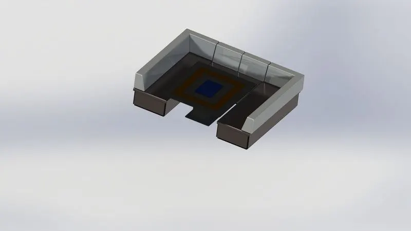
MIDDLE SEAT:Middle seat is situated at the tail side of the super structure for seating.COMMAND USED:
- Extrude boss
- Extrude cut
- Mirror
- Chamfer
- Fillet
MODELLING PROCEDURE:
- Open the blue print setup file and save it by the name front seat.
- Insert the hull part by selecting the surface bodies.
- The middle seat look like an asymmetric model so it can be created with half body and then apply mirror feature
- Draw L shape sketch on the deck surface and extrude it to get the bottom structure of the seat.
- Create a rectangle sketch on a new plane for the seat and extrude it.
- Create back support by using extrude feature.
- Apply fillet and mirror the bodies.
- Create a sketch for the table base at front of the seat.Sketch the face features to get the table support and extrude it,Then sketch the table plate and extrude it.
- Finally apply appearance.
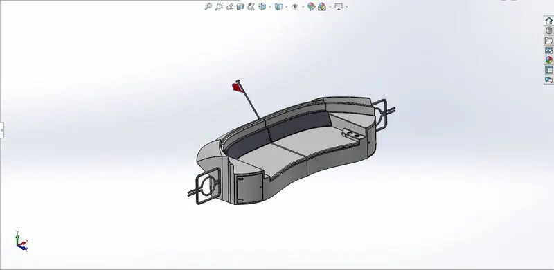
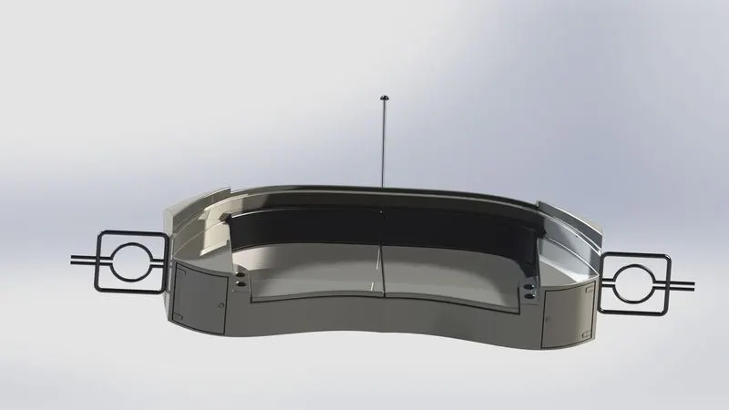
REAR SEAT:Rear seat is situated at the tail side of the hull.
COMMAND USED:
- 3D sketch
- Refrence plane
- Swept surface
- Loft surface
- Offset surface
- Extend surface
- Extrude surface
- Trim surface
- Knit surface
- Extrude boss
- Revolve boss
- Extrude cut
- Fillet
- Chamfer
- Mirror
- Swept Boss
MODELLING PROCEDURE:
- Open the blue print set up file and save it by the name Front seat.
- Insert the hull part by selecting the surface bodies.
- The main body of the rear seat is modeled using swept surface,offset surface and the remaining portion is trimmed using the trim surface tool.
- By using the refrence plane the seats are created with the help of lofted surface,Trim and extended surface.
- The flag post is created using Revolved boss/base and the flag was created by drawing the required 3D sketch and then the 3D sketches lofted to form the flag.
- The tail lamps were created by using Extrude Boss/Base,fillets and mirror tool.
- The steel gates for stairs was designed by using the refrence plane and the swept surface.
- To remove the gaps all the surfaces must be knitted together using Knit surface.
- The required fillets and chamfer were applied before mirroring the second half using the mirror tool and after mirroring the fillets was applied to the remaining.
- Finally save the part by adding appropriate appearances.
SUPER STRUCTURE:
A superstructure is an upward extension of an existing structure above a baseline.It is an extended construction of any building or platform that rises above the rest of the building or platform distinctly.
COMMAND USED:
- 3D sketch
- Refrence plane
- Swept surface
- Loft surface
- Offset surface
- Extend surface
- Extrude surface
- Trim surface
- Knit surface
- Extrude Boss
- Revolve Boss
- Extrude cut
- Fillet and chamfer
- Mirror
- Swept Boss
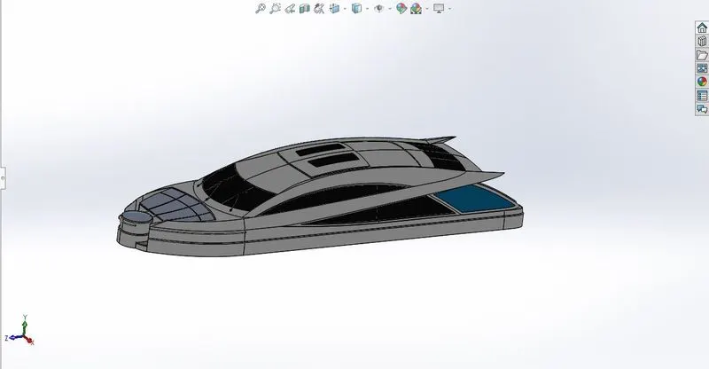
MODELLING PROCEDURE:
- Open the blue print setup file and save it by the name front side.
- Install the hull part by selecting the surface bodies
- The side surface of the superstructure is created by using extrude surface,lofted surface,fillet surface,trim surface and knit surface.
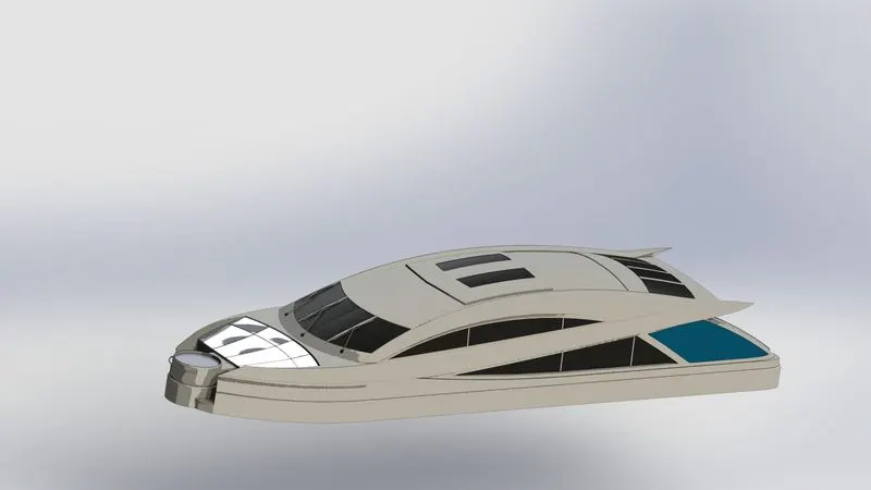
- The front side of the superstructure was designed to have four rest beds which were created using extrude boss/base,fillets and dome.
- The front edge of the superstructure was provided with a water feature which was created using extruded boss/base,extruded cut and filled with a water appearance.
- The windshield was created by extruded cut and the wipes were created by using 3D sketch and refrence plane with the help of swept boss/base
- The portholes for the superstructure were created by using extrude surface,trim surface and extend surface.
- The ruled surface used to fill the left out edges.
- The back doors of the superstructure were created using extrude cut,fillets and a refrence plane.
- Then all the surface generated were knitted together to form a solid body
- The superstructure consist of two surface bodies and five solid bodies.
- One of the surface was the deck surface the other one was used to place the radar mast so it was renamed as radar mast refrence surface.
- Then the other half model mirrored and the applied fillets.
- Apply the appearances and finally save the part.
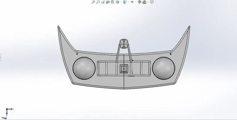
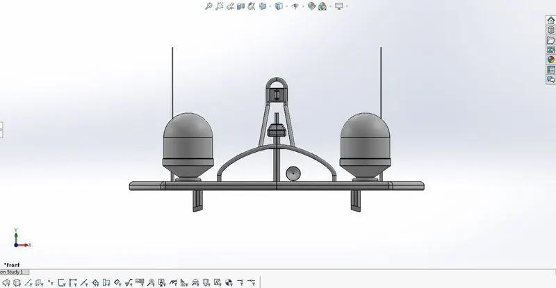
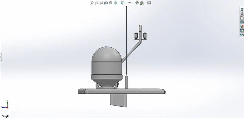
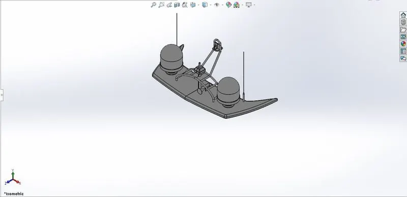
RADAR MAST:
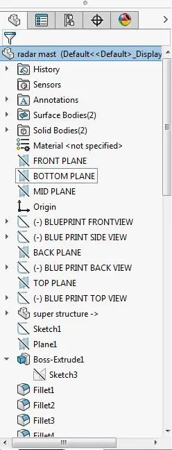
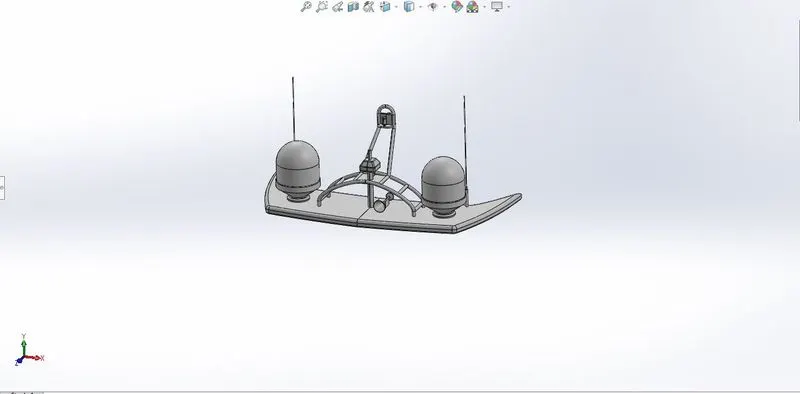
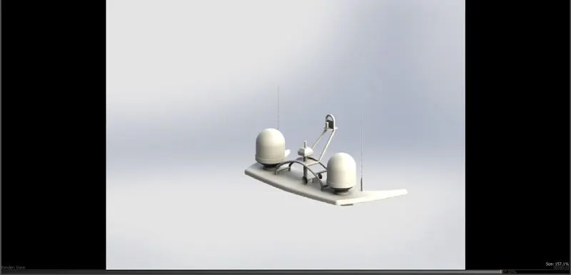
A mast is apole that rises vertically from a ship and supports the sails.The most of a sailing vessels is a tall spar or arrangements of spars,erected more or less.Vertically on the centre line of a ship.Its purpose include carrying sails,spars and derricks and giving necessary height to a navigation light too out position,signal yard,control position,radio aerial or signal lamp.Large ship have several masts with the size and configuration depending on the style of the ship.Nearly all sailing masts are guyed.
COMMAND USED:
- Extrude Bass
- Revolve Bass
- Swept Bass
- Mirror
- Fillet and chamfer
- Plane
- Shell
- Project curve
MODELLING PROCEDURE:
- Open the blueprint setup file and save it by the name Front seat
- Insert the superstructure part by selecting the surface bodies option
- Create a sketch on the surface of the radar mast by drawing a horizontal line from the surface and apply fillets to the outer and inner edges.
- Draw 4 splines and a line as per blueprint and extrude it on the created plane
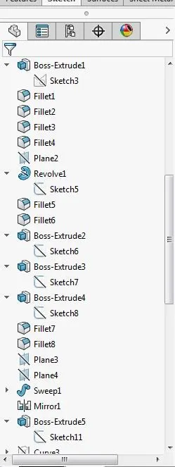
- For radar indicators sketch the top face of the previous extrude using a line and 3 points arc,revolve it.Draw a circle on the extruded face and extrude it and apply fillets.
- Antenna: create a sketch on Extrude face by drawing a circle and extrude it.Draw one more circle on the extruded face and extrude it.Create one more extrude on the previous extrude face by drawing a circle.
- Create a sweep by sketching on a created plane using a spline and circle on a 3D sketch.
- The mirror above sweep across plane 2 and connect them by drawing three circle on a sweep and extrude them.
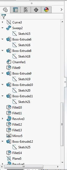
- Create a projected curve as per requirement by drawing sketches on respective plans.
- Create a sweep by drawing a circle at the edges of the projected curve.
- Horn:Draw a few lines and splines as per the blue print.Use revolved boss and apply dome to one end and shell to another end.
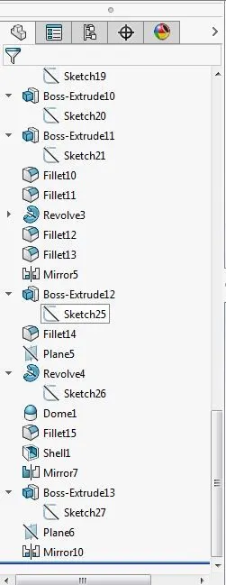
- Mirror everything except horn across mid plane
- Horn support.Draw a straignt slot on extruding one face and extrude up to the horn face.
- Create a plane using the above the extruded right face and offset it.Mirror the horn and its support across the created plane.
- Finally apply the appearance to Radar mast,Antenna,Horn and indicators.
ASSEMBLY OF DESIGNED COMPONENT/PARTS:
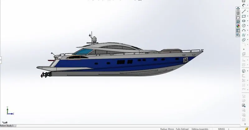
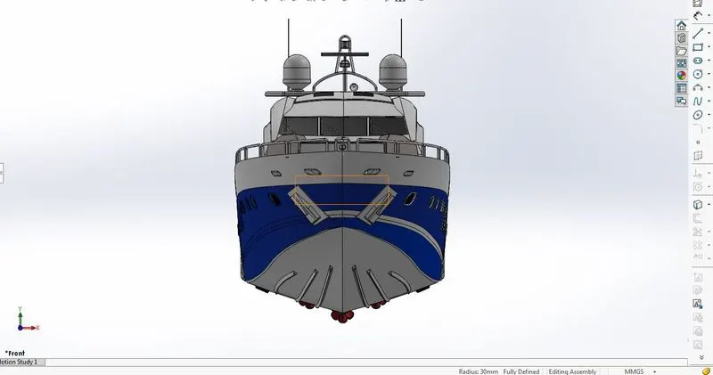
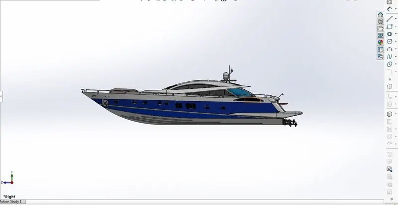
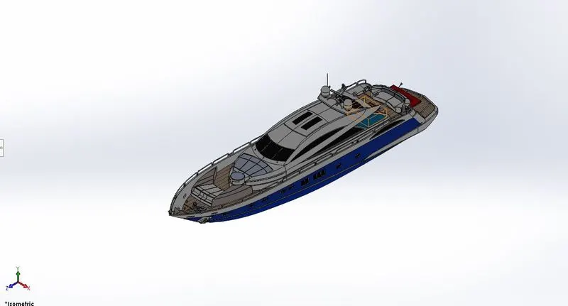
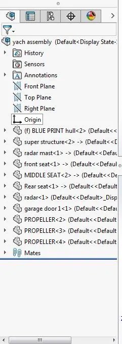
In this portion all the designed individual components are assembled together for sunseeker Yacht design.
STEPS TO BE FOLLOWED:
- Apply mate condition with respective parts for giving extact location in Assembly.
- In this Assembly only Rear seat,Radar and Propeller are located using coincident and concentric relations with respective parts,other parts are already fixed(using surfaces as refrence) so no need of giving seprate mate condition.
RENDER IMAGES: PHOTO VIEW 360:
- Insert component: Add an existing parts or sub assembly to the assembly.
- Mates: Position two components relative to one another.
APPLYING DECALS,CAMERA SET UP AND SCENES:
In this section Decals(special designed papers) are applied to
HULL:Main floor,Mood Board,Front end and Staircase.
SUPERSTRUCTURE:Staircase.
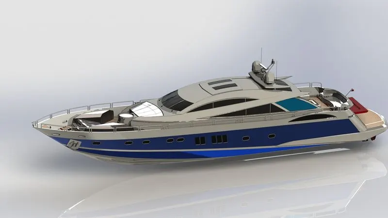
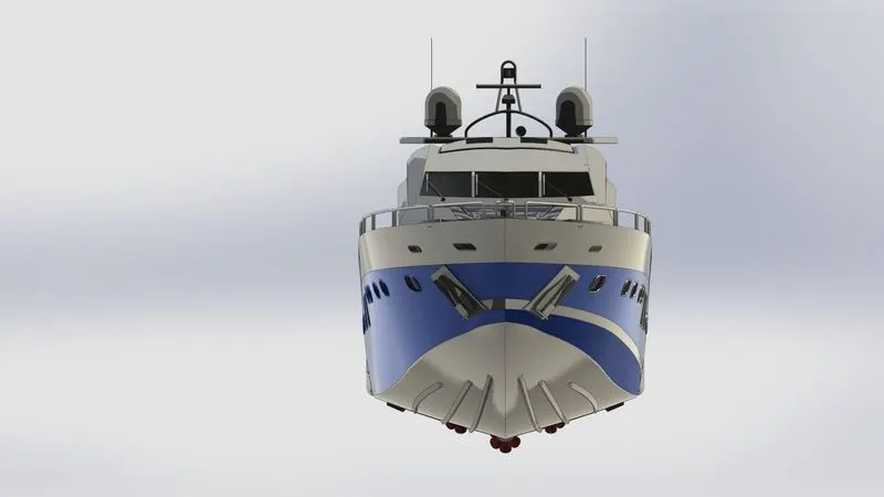
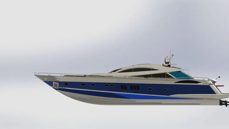
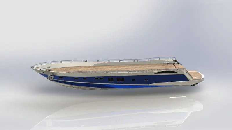
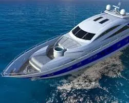
FINAL RENDERING:In this yacht assembly rendered to make it more realistic using photo view 360 and solidworks visualize.
STEPS TO FOLLOW:
- IMPORT: Import assembly once created a new project.
- APPEARANCES:Give appropriate appearances to various parts to make more attractive after rendering.
- SCENES: Use proper back plates/environment as scenes and drag the Assembly at proper location.
- OUTPUT:Once done with all setup,quick renders help you out to review final output.Changes the colour by increasing/decreasing various values for better look if required,then go for final quality rendering.
CONCLUSION:
At the end of project each and every component of sunseeker yacht designed in part files and all of them assembled together in Assembly files to get a complete design of yacht.Decals,canera setup and proper scenes are used to give realistic appearance while final rendering.
RADAR MAST: