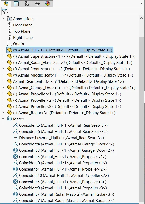
Radar Mast & Final Assembly of Yacht
DESIGN ASSEMBLY AND PHOTO REALISTIC RENDERING OF SUNSEEKER PREDATOR YACHT USING SOLIDWORKS AND SOLIDWORKS VISUALIZE
OBJECTIVE
- The objective is to get detailed understanding of the surface modelling using SOLIDWORKS
- To Design individual parts of the yacht with fully defined sketches and appropriate appearance.
- To Assemble all the designed parts of the yacht model by assigning suitable constraints.
- To Render the yacht model by adding appearance decals lights cameras and background scenes.
INTRODUCTION
SOLIDWORKS is a design automation software and it is published by Dassault System. It is a solid modelling software that allows to design products in three dimensions. It is computer aided design program which helps to draw any simple or complex mechanical shapes or assembling and drawing.
Surface modelling is the method of showing or presenting solid object.The process requires you to convert between different 3D modeling types, such as converting the 3D object to show procedural surfaces, validate imperfections, and apply smoothness.Surface modeling focuses more on the external aspects of an object. It develops an object by stretching a surface over it with 3D curves created by the designer. It is essentially describing the surface boundaries of the object. It allows the viewer to see at each surface point where the solid interior is located.
A yacht is a watercraft used for pleasure and sport. The name comes from the Dutch word jacht means 'hunter', referred as fast, light sailing vessel that the dutch republic navy used to chase pirates and other transgressors around and into the shallow waters of low countries .Sun-seeker yacht belong to British Lux-ray performance motor brand who’s originally named as Poole Power Boat later changed name to Sun-seeker International in 1985. It was founded by Robert & John Braithwaite in01969.
Design of the yacht has many components which require surface modelling, hnece taking this project helps in learning surface modelling techniques and its command in solidworks and application of it in real world design.
COMMANDS AND FEATURES USED
- General:- Sketch, Smart Dimension, 3D Sketch (line, rectangle, circle, spline, arc, polygon, fillet, ellipse), Offset Entities, Trim and Extend Entity, Convert Entity, Mirror Entities, Linear/Circular Pattern, Dynamic mirror.
- Solid Model:-Extruded Bose/Base, Revolved Bose/Base, Swept Bose/Base, Lofted Base/Boss, Extruded Cut, Swept Cut, Lofted Cut, Fillet, Chamfer, Circular &Linear Pattern, Shell, Dome ( Face dome/ elliptical dome), Split, Combine(Add/Subtract/Common).
- Surface Model:- Swept Surface, Lofted Surface, Boundary Surface, Filled Surface, Surface Trim, Extended Surface, Surface Knit, Offset Surface, Delete Face.
DESIGN METHODOLOGY OF SUNSEEKER PREDECTOR YACHT
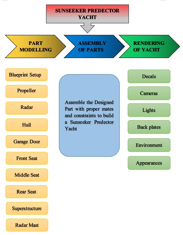
PART MODELLING OF SUNSEEKER PREDECTOR YACHT
1. BLUEPRINT SETUP
Description- Blueprint is basically a design plan or technical drawings of different orthographic views of a product. The main objective of the blueprint is to bring out the exact same shape and form of the product as designed by a designer. It also ensures the accuracy and the proportion of the product. Designing a product without a blueprint may lead to multiple errors, unnatural proportions and improper dimensions. A proper blueprint setup omits all those problems.
To set up a blueprint, we use sketch mode in SOLIDWORKS in each plane. In this case, the images provided for the front view, side view,back view, bottom view and top view are added in the respective planes. One very important thing to note while setting up a blueprint is the size of it. As all the parts are going to be designed laying up the blueprint and taking its reference, it is very crucial to maintain the correct and real size of the blueprint in the dimensions or by adjusting the scale bar.
Figure 1 : Shows the Blueprint setup of the yacht model
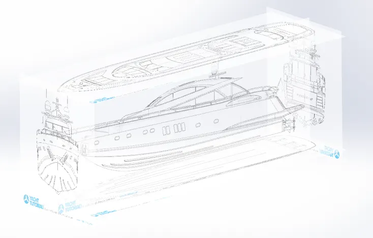
Figure 1- Blueprint setup of the yacht model
2. PROPELLER
Description- A propeller is a device with a rotating hub and radiating blades that are set at a pitch to form a helical spiral, that, when rotated, exerts linear thrust upon a working fluid, such as water or air. Propellers are used to pump fluid through a pipe or duct, or to create thrust to propel a boat through water or an aircraft through air. The blades are specially shaped so that their rotational motion through the fluid causes a pressure difference between the two surfaces of the blade by Bernoulli's principle which exerts force on the fluid. Most marine propellers are screw propellers with helical blades rotating on a propeller shaft with an approximately horizontal axis.
Figure 2 : Shows the 3D model of the Propeller using SOLIDWORKS
Figure 3: Shows the Rendering image of Propeller using Photo-view 360
Features and Tools used to create Propeller
- Sketch
- Line
- Circle
- Rectangle
- Loft
- Revolve
- Circular pattern
- Fillet
- Extrude cut
- Appearance
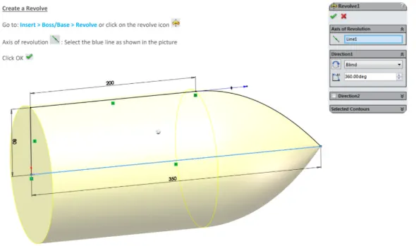
i. REVOLVE:
To create a revolve feature: Create a sketch that contains one or more profiles and a centre line, line, or edge to use as the axis around which the feature revolves. Click one of the following revolve tools: Revolved Boss/Base (Features toolbar) or Insert > Boss/Base > Revolve.
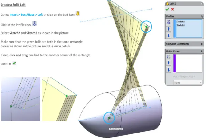
ii. LOFT:
The loft feature in SOLIDWORKS allows you generate complex geometry in a single feature. It does this by interpolating surfaces between various cross-sections of a model. These cross-sections can be sketches, faces, or edges. In the loft interface, these cross-sections are considered “Loft Profiles”.
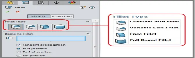
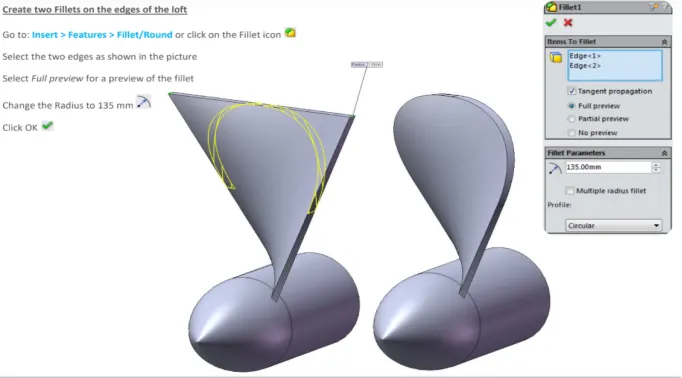
iii. FILLET:
Fillet/Round creates a rounded internal or external face on the part. You can fillet all edges of a face, selected sets of faces, selected edges, or edge loops.
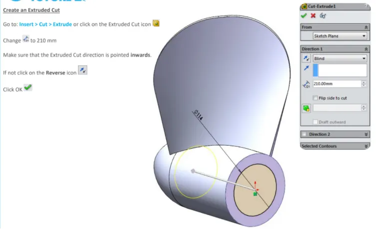
iv. CUT EXTRUDE:
To create an extruded cut:
1) Sketch the profile for cut.
2) Click Extruded Cut on the Features toolbar or select Insert, Cut, Extrude on the menu bar.
3) Under Direction 1, do the following:Select an End Condition. Examine the preview and if necessary, click Reverse Direction to extrude in the opposite direction.
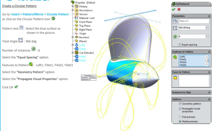
v. CIRCULAR PATTERN:
Use circular patterns to create multiple instances of one or more features that you can space uniformly around an axis.
To create a circular pattern:
1) Create one or more features to replicate.
2) Click Circular Pattern (Features toolbar) or Insert > Pattern/Mirror > Circular Pattern.
3) Set the Property Manager options.
4) Click OK.
vi. APPERANCE:
To give colour to the body or face
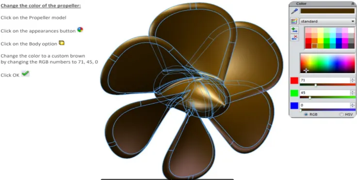
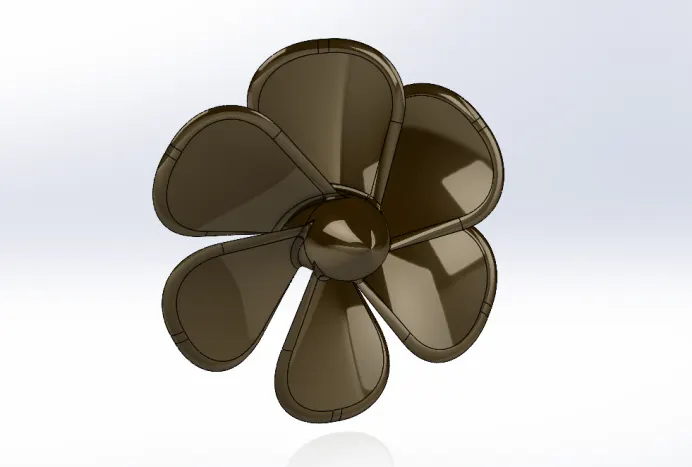
Figure 2- 3D Model of Propeller
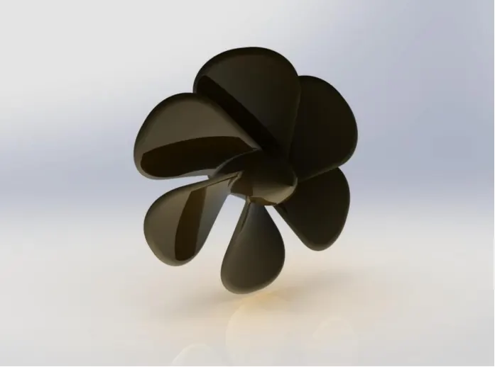
Figure 3- Rendering Model of Propeller
3. RADAR
Description- Marine radars are X band or S band radars on ships, used to detect other ships and land obstacles, to give bearing and distance for collision avoidance and navigation while on water. A marine radar device acts as a major navigation aid for boaters. It helps in detecting boats, birds, landmasses, and weather systems - even if the visibility is less than usual. A radar has a flat antenna that spins, emitting a signal, them listening back for that signal. The return signal bounces back at varying times based on what it may be bouncing off. This is the part used for the GPS and navigation of the ship.
Figure 4 : shows the 3D model of the Radar using SOLIDWORKS
Figure 5: shows the Rendering image of Radar using Photo-view 360
Features and Tools used to create Radar
- Sketch
- Polygon
- Circle
- Line
- Extrude Boss
- Extrude cut
- Sketch pattern
- Mirror
- Fillet
- Split Line
- Text
- Appearance
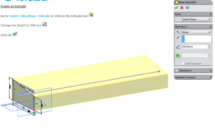
i. BOSS EXTRUDE:
It is used to make 2D sketch into solid body.
Extrude Property Manager .
1) Create a sketch.
2)Click one of the extrude tools: Extruded Boss/Base. on the Features toolbar, or click Insert > Boss/Base > Extrude. Extruded Cut. on the Features toolbar, or click Insert > Cut > Extrude. Extruded Surface. On the Surfaces toolbar, or click Insert > Surface > Extrude.
ii. MIRROR:
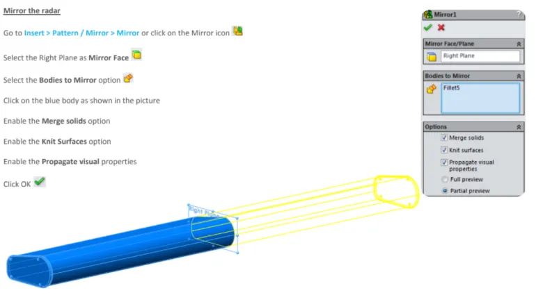
It is used to make a copy of the sketch along a reference axis/plane/line.
To mirror a feature: Do one of the following: In a part, click Mirror (Features toolbar) or Insert > Pattern/Mirror > Mirror. In an assembly, click Assembly Features (Assembly tab on the Command Manager) and click Mirror or click Insert > Assembly Feature > Mirror.
iii.SKETCH DRIVEN PATTERN:
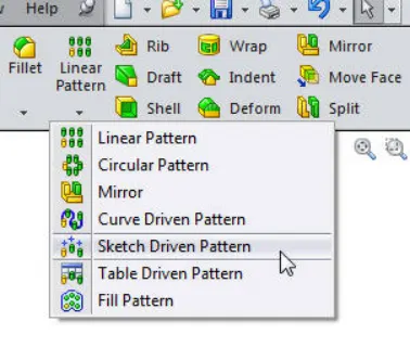
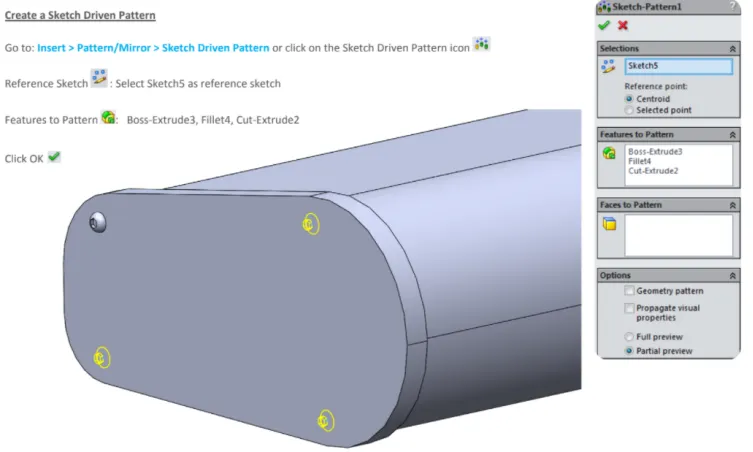
It is used pattern features over a sketched point.
Solid works Pattern a Sketch
To build a sketch driven pattern:
1) Open a sketch on the face of a part.
2) Create a seed feature on the model.
3) Click Point or Tools > Sketch Entity > Point, and add multiple sketch points to represent the pattern you want to create, based on the seed feature.
4) Close the sketch.
iv. SPLIT LINE:
Using the split lines feature, the sketch lines are projected onto the selected faces, and divide the faces into multiple regions as defined by the sketch. Once the split line is created, these selected regions can have a different appearance than the other regions, and function as a separate face.
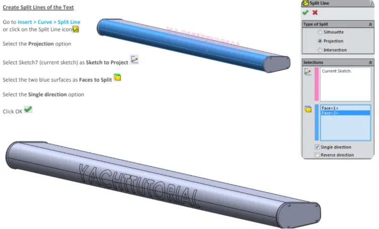
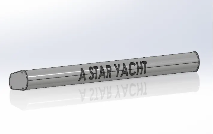
Figure 4- 3D Model of Radar
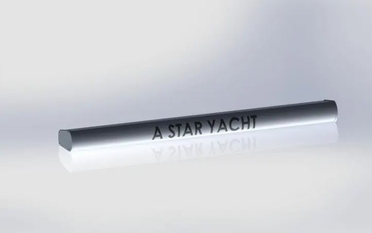
Figure 5- Rendering Model of Radar
4. HULL
Description- The hull of a ship is the most notable structural entity of the ship. To define the hull, it can be said that it is the watertight enclosure of the ship, which protects the cargo, machinery, and accommodation spaces of the ship from the weather, flooding, and structural damage.
Figure 6 : shows the 3D model of the Hull using SOLIDWORKS.
Figure 7: shows the Rendering image of Hull using Photo-view 360.
Features and Tools used to create Hull
- Sketch
- Offset
- Entities
- Project curves
- Lofted Surface
- Trim surfaces
- Extended surface
- Knit Surface
- Filled Surface
- Shell
- Extrude Bose
- Extrude Cut
- Fillet
- Dome
- Chamfer
- Swept Boss
- Revolved Boss
- Linear Pattern
- Helix/Spiral
- Combine
- Mirror
- Delete face
- 3D sketch
- Split body
- Offset Surface
- Appearances
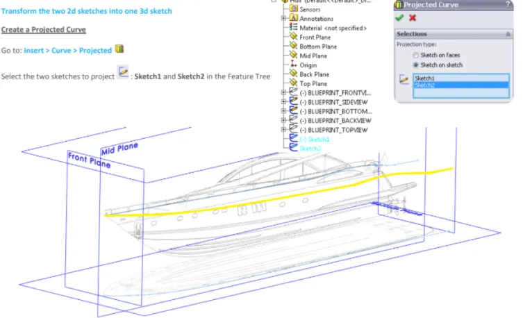
i. PROJECT CURVE:
To project a curve: Click Project Curve on the Curves toolbar, or Insert > Curve > Projected. Use this selection to project a sketched curve onto a model face. Under Sketch to Project, select the curve in the graphics area or from the fly-out Feature Manager design tree.
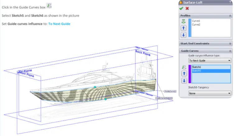
ii. SURFACE LOFT:
It creates a lofted surface between two or more profiles or sketches by specifying the start and end constraints along guide curves to control the path shape.
To create a lofted surface:
1) Create a plane for each profile section of the loft. The planes do not need to be parallel.
2) Sketch the section profiles on the planes.
3) If necessary, create guide curves.
4) Click Lofted Surface (Surfaces toolbar) or Insert > Surface > Loft.
5) Set the Property Manager options.
6) Click OK.
iii. SURFACE TRIM:
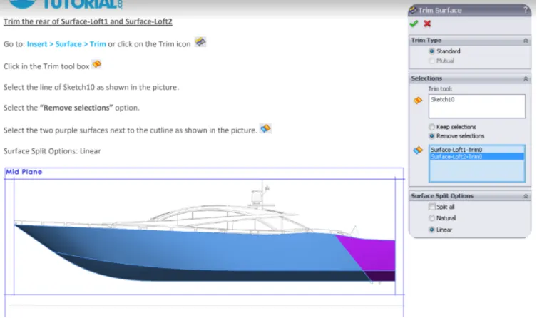
It trims the surfaces where a surface intersects with another surface, a plane or a sketch.
To trim a surface:
1) Create two or more surfaces that intersect at one or more points, or create a surface that intersects with a plane or has a sketch on its face.
2) Click Trim Surface on the Surfaces toolbar, or click Insert > Surface > Trim.
3) In the Property Manager, under Trim Type, select a type:
a. Standard Trims surfaces using surfaces, sketch entities, curves, planes, and so on.
b. Mutual Trims multiples surfaces using the surfaces themselves.
4) Under Selections, choose from these options:
5) Trim tool (available with Standard selected under Trim Type). Select a surface, sketch entity, curve, or plane in the graphics area as the tool that trims other surfaces.
6) Surfaces (available with Mutual selected under Trim Type). Select multiple surfaces in the graphics area for Trimming Surfaces to use to trim themselves.
7) Select a trim action:
a. Keep selections. Retains the surfaces listed under Pieces to Keep . Intersecting surfaces not listed under Pieces to Keep are discarded.
b. Remove selections. Discard the surfaces listed under Pieces to Remove . Intersecting surfaces not listed under Pieces to Remove are retained.
8) Select surfaces in Pieces to Keep or in Pieces to Remove , based on the trim action.
9) If you selected Mutual Trim, Preview options are available. Select one of the following:
|
Show included surfaces |
Displays the regions that you are including as surfaces. All other surfaces are hidden. |
|
|
Show excluded surfaces |
Displays the surfaces that you are excluding as transparent. All other surfaces are hidden. |
|
|
Show both included and excluded surfaces |
Displays both included and excluded surfaces. Excluded surfaces appear transparent. |
10) Under Surface Split Options, select an item:
a. Boundaries extend tangent from the ends of the Trim tool.
b. Boundaries extend from the Trim tool endpoints to the nearest edge.
11) Optionally, select Split All.
12) Example; Trim Surface- Surface Split Options
13) Click OK.
iv. SURFACE EXTRUDE:
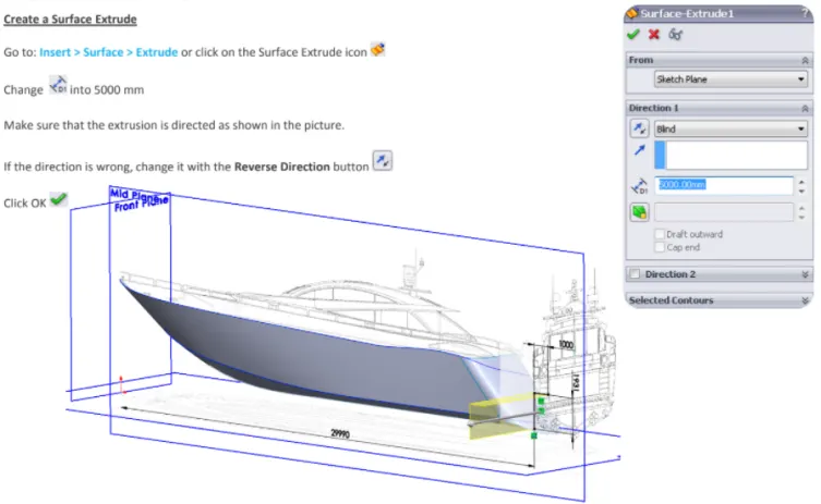
It extrudes a sketch or selected sketch contours to create a surface feature in one or two directions
Extruding Surfaces from a 2D or 3D Face
1) Click Insert > Surface > Extrude.
2) Select a face:
3) Select other faces to define the extrude as required. ...
4) Select the end condition.
5) For 3D faces, select a plane, edge, 2D face, or sketch line to define the direction of extrusion.
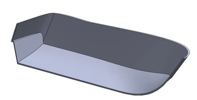
v. SHELL:
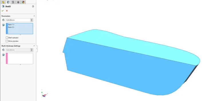
The shell tool hollows out a part, leaves open the faces you select, and creates thin-walled features on the remaining faces. If you do not select any face on the model, you can shell a solid part, creating a closed, hollow model. You can also shell a model using multiple thicknesses.
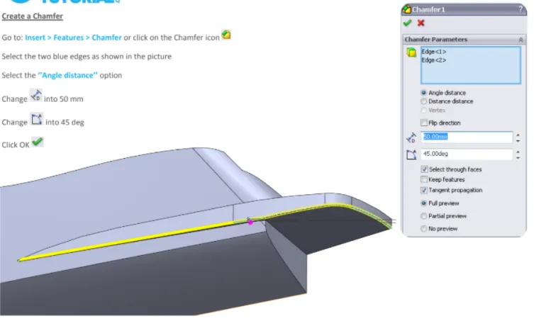
vi. CHAMFER:
The chamfer tool creates a bevelled feature on selected edges, faces, or a vertex.
To create a chamfer:
1) Click Chamfer (Features toolbar) or Insert > Features > Chamfer.
2) Under Chamfer Parameters, select an item and set parameters. ...
3) Click OK
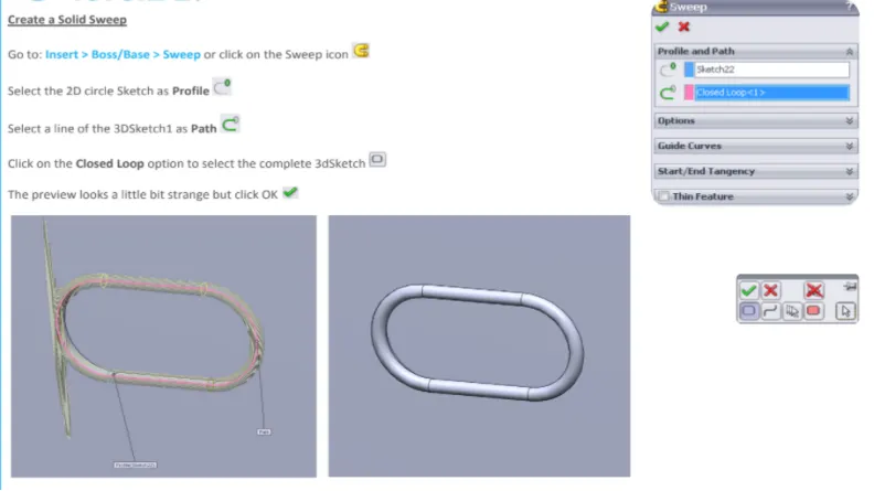
vii. SWEEP:
It is used to make a solid body which follows a particular axis,known as swept axis. It is used for making uneven solid bodies.
To create a sweep:
1) Sketch a closed, non-intersecting profile on a plane or a face. If you use guide curves:
2) Create the path for the profile to follow. Use a sketch, existing model edges, or curves.
3) Click one of the following:
4) In the Property Manager:
5) Set the other Property Manager options.
6) Click OK
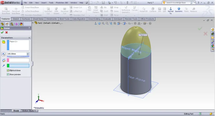
viii. DOME:
It is used to create a dome that is tangent to the adjacent cylindrical or conical faces.
1) Click Dome on the Features toolbar, or click Insert > Features > Dome.
2) Select one or more planar or non-planar faces.
3) Set a value for the distance by which the dome expands.
4) Click to create a concave dome (default is convex).
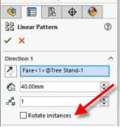
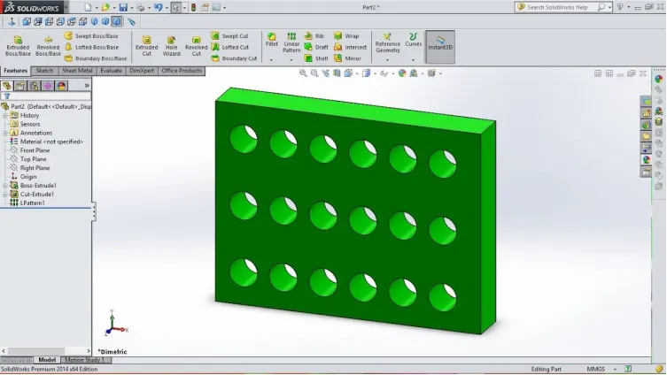
ix. LINEAR PATTERN:
It is used to make linear patterns for solid bodies or cuts along a reference line
To create a linear sketch pattern:
1) In an open sketch, click Linear Sketch Pattern. (Sketch toolbar) or Tools > Sketch Tools > Linear Pattern.
2) In the Property Manager, under Entities to Pattern, select the sketch entities to pattern.
3) Set values for Direction 1 (X-axis)
4) Repeat for Direction 2 (Y-axis).
5) Click OK.
You can use linear patterns to create multiple instances of one or more features that you can space uniformly along one or two linear paths. Seed feature. Linear pattern - two directions. Linear pattern - one direction.
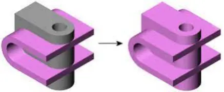
x. COMBINE:
To add bodies together:
1) Click Combine. (Features toolbar) or Insert > Features > Combine.
2) In the Property Manager, under Operation Type, select Add.
3) For Bodies to Combine, select the bodies to combine. You can select bodies in the graphics area or the Solid Bodies.
4) Click Show Preview to preview the feature.
5) Click OK.
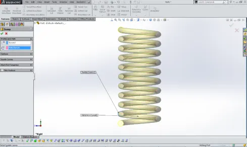
xi. HELIX/SPIRAL:
The diameter of the circle controls the starting diameter of the helix or spiral. Click Helix and Spiral (Curves toolbar) or Insert > Curve > Helix/Spiral. Set values in the Helix/Spiral Property Manager. Click OK.
xii MOVE/COPY/DELETE THE BODY:
To move, copy, rotate, or mate a solid or surface body:
1) Click Move/Copy Bodies (Features toolbar) or Insert > Features > Move/Copy. Specify parameters to move, copy, or rotate bodies.
2) Apply mates between bodies.
3) Click Delete/Keep Body on the Features toolbar, or click Insert > Features > Delete/Keep Body.
4) In the Property Manager, select Delete Bodies or Keep Bodies. For Bodies to keep or Bodies to delete, select bodies in the graphics area or from the Solid Bodies folder for Solid/Surface Bodies to Delete/Keep.
5) Click OK.
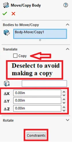
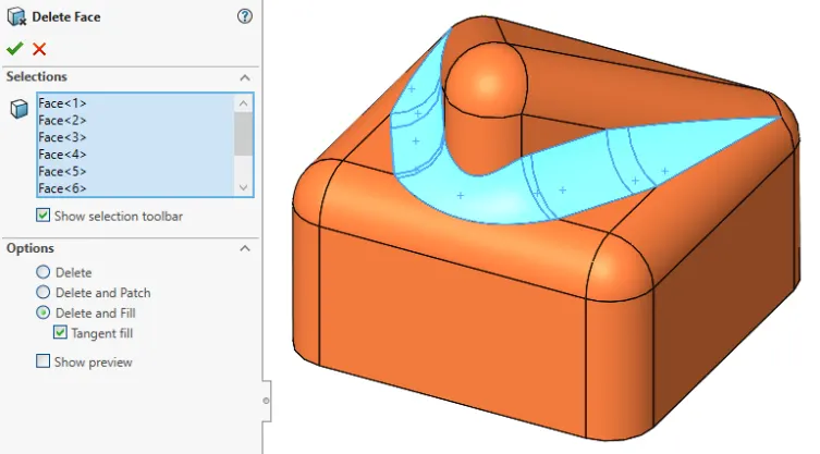
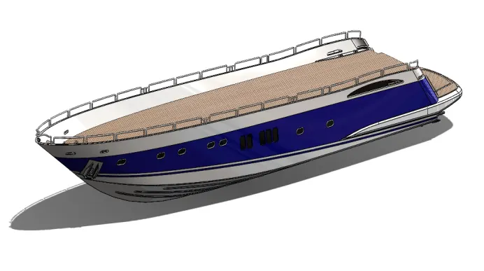
Figure 6- 3D Model of Hull
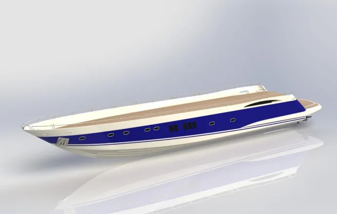
Figure 7- Rendering Model of Hull
5. GARAGE DOOR
Description- A garage door is a large door on a garage that opens either manually or by an electric motor (a garage door opener). Garage doors are frequently large enough to accommodate automobiles and other vehicles. Small garage doors may be made in a single panel that tilts up and back across the garage ceiling.It was created out of the splited block from the Hull. It is provided with two holes to adjust the pins in order to open or close the garage door. It encloses the garage space which can accommodate a locomotive inside it.
Figure 8 : shows the 3D model of the Garage Door using SOLIDWORKS
Figure 9: shows the Rendering image of Garage Door using Photo-view 360
Features and Tools used to create Garage Door
- Extrude Cut
- Mirror
- Text
- Fillet
- Shell
- Plane
- Appearances
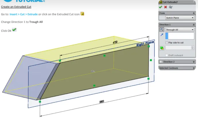
i.CUT EXTRUDE:
It is used to cut through a solid body
To create an extruded cut:
1) Sketch the profile for cut.
2) Click Extruded Cut on the Features toolbar or select Insert, Cut, Extrude on the menu bar.
3) Under Direction 1, do the following:Select an End Condition. Examine the preview and if necessary, click Reverse Direction to extrude in the opposite direction.
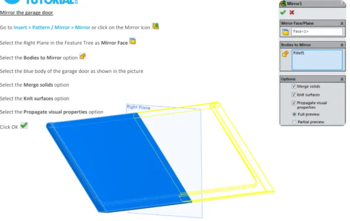
ii.MIRROR:
It is used to make a copy of the sketch along a reference axis/plane/line.
To mirror a feature: Do one of the following: In a part, click Mirror (Features toolbar) or Insert > Pattern/Mirror > Mirror. In an assembly, click Assembly Features (Assembly tab on the Command Manager) and click Mirror or click Insert > Assembly Feature > Mirror
iii. SHELL:
The shell tool hollows out a part, leaves open the faces you select, and creates thin-walled features on the remaining faces. If you do not select any face on the model, you can shell a solid part, creating a closed, hollow model. You can also shell a model using multiple thicknesses.
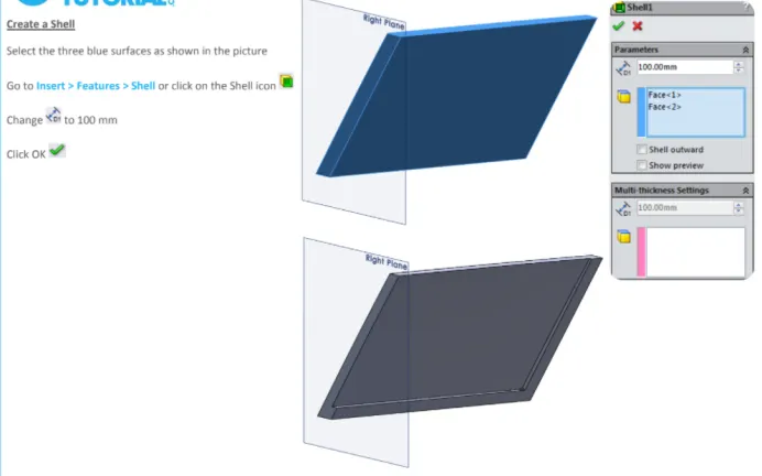
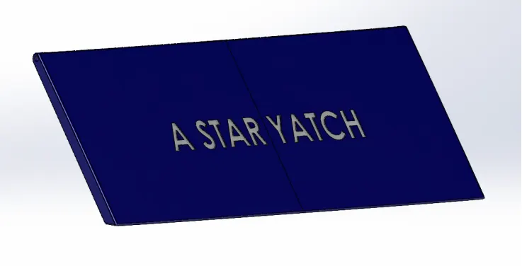
Figure 8- 3D Model of Garage Door
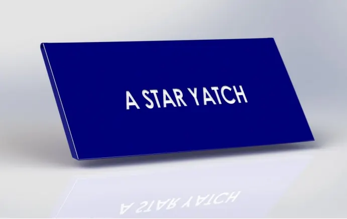
Figure 9- Rendering Model of Garage Door
6. FRONT SEAT
Description- A seat is a place to sit. The term may encompass additional features,such as back,armrest,head restraint but also headquarters in a wider sense. It is designed with reference to the deck surface and the blueprints. It is designed using surface features and also extrude features. Domes are applied to the surface to imitate cushions of the seat. A small water pool lies in the superstructure behind the front seat. It may also comes under luxuries, materials uses for the seat etc. Here, this seat position on front side of the yacht. The front seat is designed on the front to have the perfect view of the ocean and can accommodate two people.
Figure 10 : shows the 3D model of the Front Seat using SOLIDWORKS
Figure 11: shows the Rendering image of Front Seat using Photo-view 360
Features and Tools used to create Front Seat
- Surface Sweep
- Surface loft
- Surface trim
- Extrude cut
- Revolve
- Surface knit
- Surface fill
- Dome
- Mirror
- Fillet
- Chamfer
- Appearances
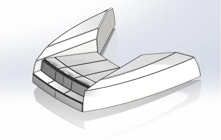
Figure 10- 3D Model of Front Seat
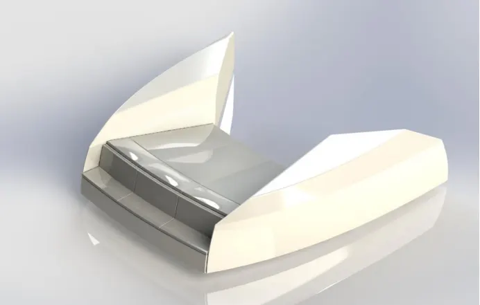
Figure 11- Rendering Model of Front Seat
7. MIDDLE SEAT
Description- The middle seat are designed to accommodate more people. It ca accommodate six people and a table is provide at the centre to have a party. This is located between superstructure and the rear seat. A seat is place to sit. The term may encompass additional features,such as back,armrest,head restraint but also headquarters in a wider sense. It is designed with reference to the deck surface as the ground and the blueprint sketches as the reference for the dimensions and the views. This part is design was done without involving surface design. It may also comes under luxuries, materials uses for the seat etc. Here, this seat position on centre of the yacht.
Figure 12 : shows the 3D model of the Middle Seat using SOLIDWORKS
Figure 13: shows the Rendering image of Middle Seat using Photo-view 360
Features and Tools used to create Middle Seat
- Sketch (Line, Rectangle)
- Extrude Boss
- Extrude cut
- Fillet
- Chamfer
- Offset entities
- Mirror
- Appearances
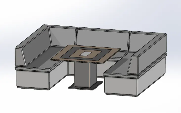
Figure 12- 3D Model of Middle Seat
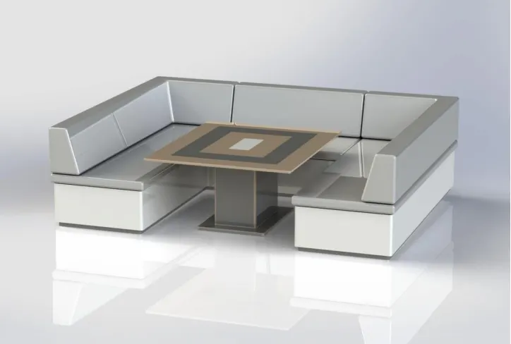
Figure 13- Rendering Model of Middle Seat
8. REAR SEAT
Description- A seat is a place to sit. The term may encompass additional features,such as back,armrest,head restraint but also headquarters in a wider sense.It may also comes under luxuries, materials uses for the seat etc. Here, this seat position on back side of the yacht. It is placed at the backhand of the hull. It can accommodate thee persons and gives a perfect view of the backside of the ocean. It is also designed with reference to the deck surface as the ground and the blueprint sketches as the reference for the dimensions and the views. It is also provide with a flag at the end which is designed as a surface to represent the natural looks of a flag in wind.
Figure 14: shows the 3D model of the Rear Seat using SOLIDWORKS
Figure 15: shows the Rendering image of Rear Seat using Photo-view 360
Features and Tools used to create Rear Seat
- Surface loft
- Surface Sweep
- Surface extrude
- Surface offset
- Surface trim
- Sweep
- Ruled surface
- Surface extend
- Surface knit
- Extrude Boss/ Base
- Extrude cut
- Fillet
- Chamfer
- Mirror
- Appearances
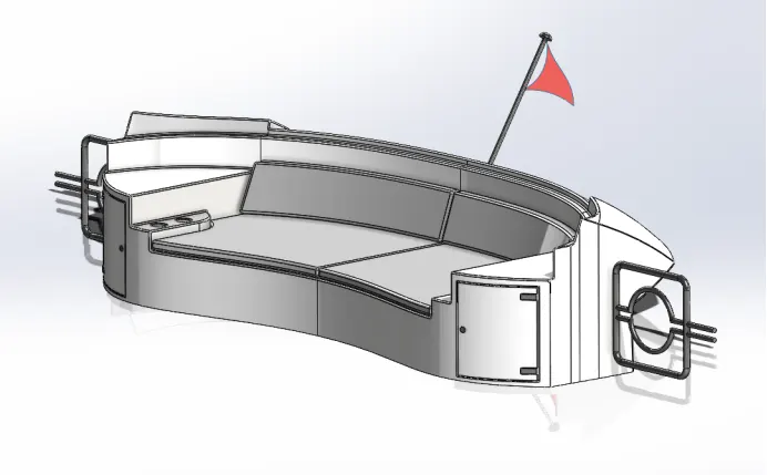
Figure 14- 3D Model of Rear Seat
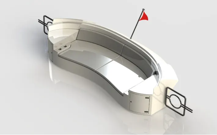
Figure 15- Rendering Model of Rear Seat
9.SUPERSTRUCTURE
Description- A superstructure is an extruded construction of any building or platform that rises the above the rest of the building or platform in a distinct manner. The word comes from a combination of two Latin words, the Latin prefix “super” means in addition or above or in excess of, whereas the stem word “structure” means to build or to head up. Thus, superstructure means to add a construction to an already existing structure. It is the part that sits on the deck surface of the yacht. In general, superstructure of a yacht consist of cockpits, mast, tables etc. For the modelling of this superstructure, the deck surface was used as a base so it is directly inserted and fixed in position in the assembly. The curves are sketched as close as the blueprint from two different views and are projected to from a 3D curve. It also includes windows, windscreen wipers, and the back doors.
Figure 16: shows the 3D model of the Superstructure using SOLIDWORKS
Figure 17: shows the Rendering image of Superstructure using Photo-view 360
Features and Tools used to create Superstructure
- Sketch ( Spline, Line, Circle, )
- Extruded cut
- Surface fill
- Surface Extrude
- Surface Sweep
- Surface Trim
- Extend Surface
- Surface Knit
- Reference plane
- Ruled Surface
- Split Lines
- Delete faces
- Fillet
- Chamfer
- Mirror
- Dome
- Offset
- Project curves
- Appearances
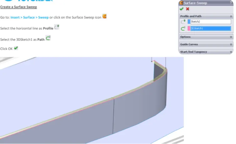
i. SURFACE SWEEP:
Surfaces sweep are surfaces that are generated from a section curve positioned along a path. Parallel Sweep is defined as a section curve moving along a guide path while maintaining the section curve to be parallel to the guide path.
1) If you are using guide curves, create coincident or pierce relations between the guide curves and the profile.
2) Click Swept Surface (Surfaces toolbar) or Insert > Surface > Sweep.
3) Set the Property Manager options. Click OK.
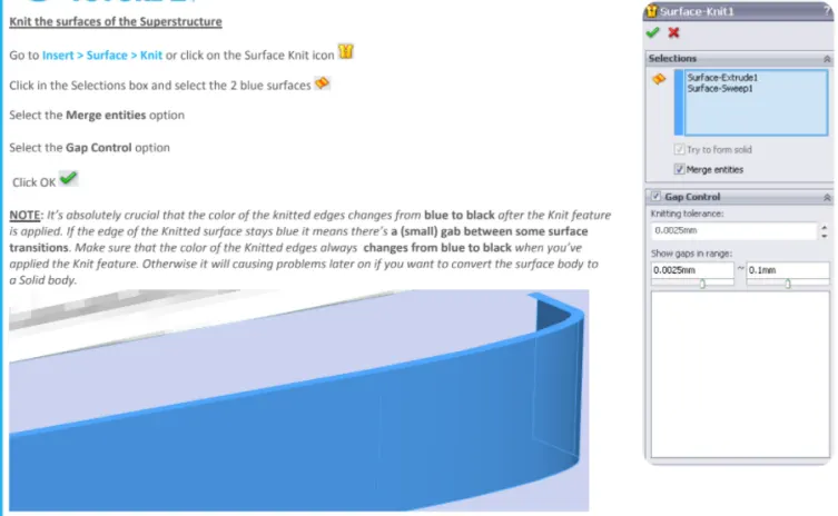
ii. SURFACE KNIT:
Use the Knit Surface tool to combine two or more faces and surfaces into one.
Note the following about knit surfaces:
1) Edges of the surfaces must be adjacent and not overlapping.
2) Surfaces do not need to be on the same plane.
3) Select the entire surface body, or select one or more adjacent surface bodies.
4) Knit surfaces absorb the surface bodies you used to create them.
5) Create a solid body when the knit surfaces form a closed volume, or leave as a surface body.
6) Select Merge entities to merge faces with the same underlying geometry.
7) Select Gap Control to view the gaps or modify the knitting tolerance.
iii. RULED SURFACE:
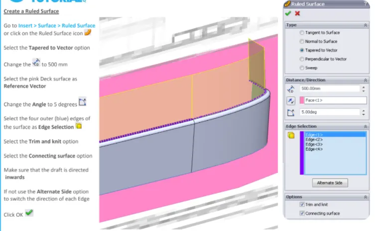
Inserts ruled surfaces in a specified direction from edges. Tangent to the surface, Normal to the surface, tapered to vector, perpendicular to vector or sweep can be selected. We can also trim and knit the surfaces and remove any connecting surfaces.
To create a ruled surface:
1) Click Ruled Surface on the mold Tools toolbar, or click Insert > molds > Ruled Surface.
2) Ruled surface is tangent to the surfaces that share an edge.
3) Ruled surface is normal to the surfaces that share an edge.
iv. SURFACE FILL:
Patches a surface within a boundary defined by edges,sketches
To create a filled surface,
1) Click Filled Surface on the Surfaces toolbar, or click Insert > Surface > Fill, set the Property Manager options, and click OK.
2) Set the Property Manager options based on the type of filled surface you want to create.
v. SURFACE EXTEND:
Extends one or more edges or faces on a surface, based on end conditions and extension type.
To extend a surface:
1) Click Extended Surface (Surfaces toolbar) or Insert > Surface > Extend.
2) In the Property manager: Under Edges/Faces to Extend, select one or more edges or faces in the graphics area for Selected Face/Edges .
3) For edges, the surface extends along the plane of the edge.
4) CLICK OK
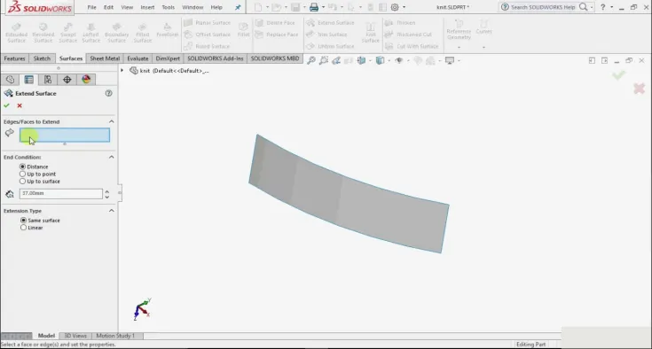
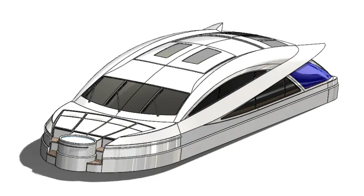
Figure 16- 3D Model of Superstructure
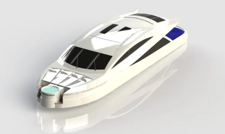
Figure 17- Rendering Model of Superstructure
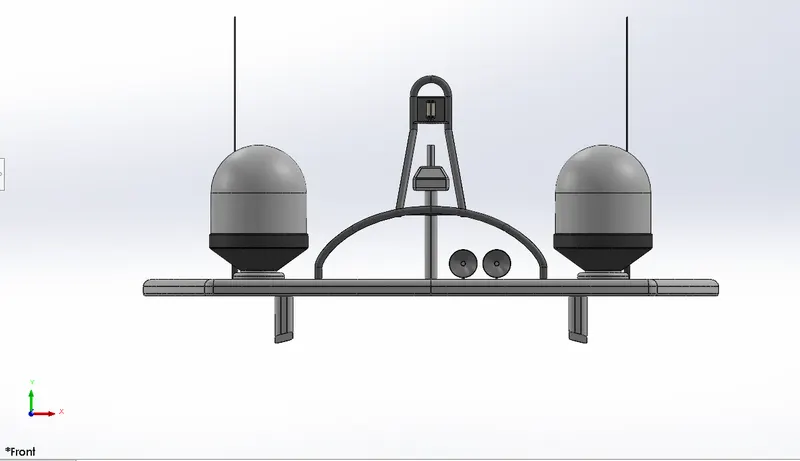
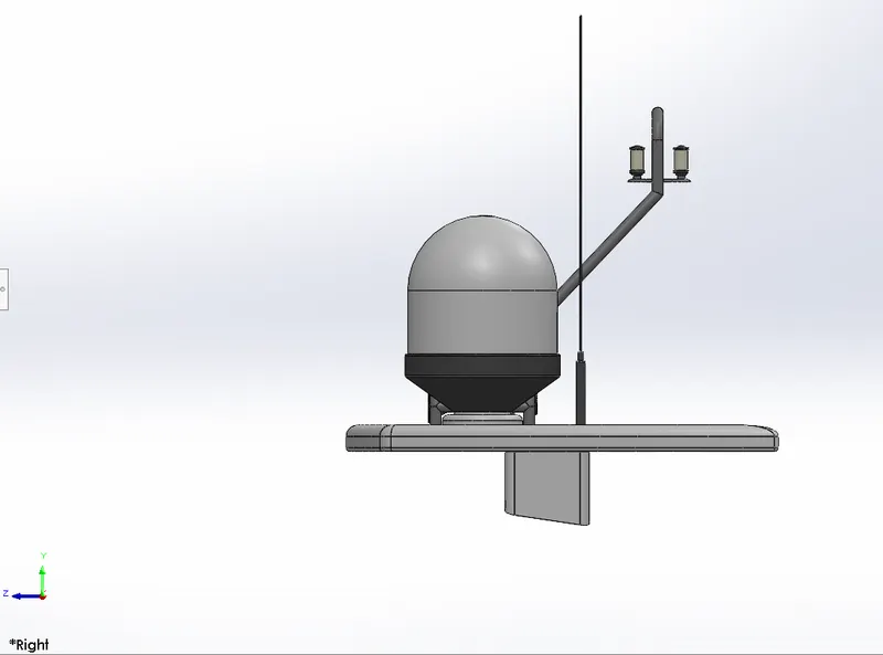
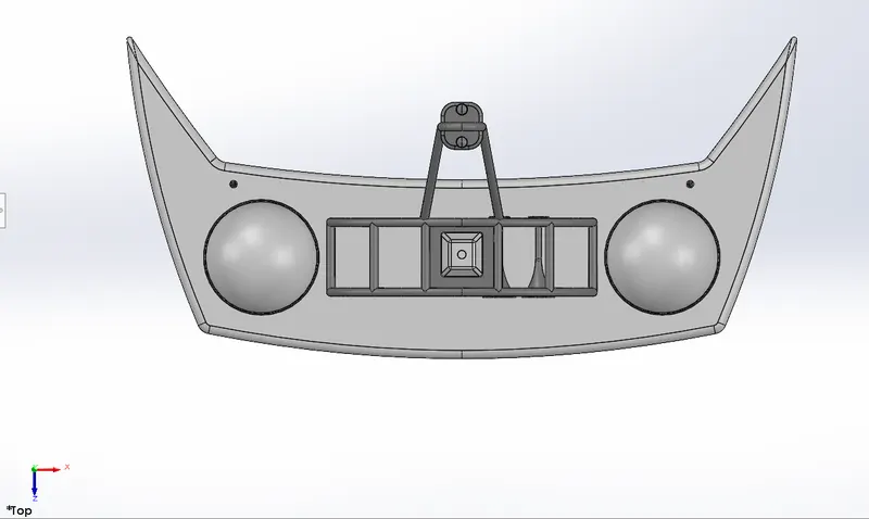
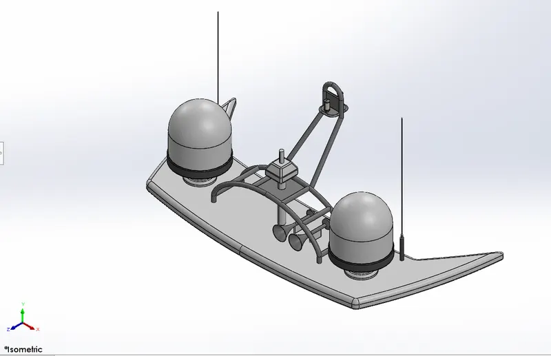
10. RADAR MAST
Description- Marine radars are X band or S band radars on ships, used to detect other ships and land obstacles, to provide bearing and distance for collision avoidance and navigation at sea. They are electronic navigation instruments that use a rotating antenna to sweep a narrow beam of microwaves around the water surface surrounding the ships to the horizon, detecting targets by microwaves reflected from them, generating a picture of the ship’s surrounding on a display screen. A radar has a flat antenna that spins, emitting a signal, them listening back for that signal. The t-return signal bounces back at varying times based on what it may be bouncing off.
It has a detection system that uses radio waves to determine the range, angle or velocity of the objects. A radar system consists of a transmitter producing electromagnetic waves in the radio or microwave domain, a transmitting antenna, a receiving antenna and receiver and processor to determine properties of the object. Radio waves from the transmitter reflect off the object an return to the receiver, giving information of the objects location and speed.
Figure 18: shows the 3D model of the Radar Mast using SOLIDWORKS
Figure 19: shows the Rendering image of Radar Mast using Photo-view 360
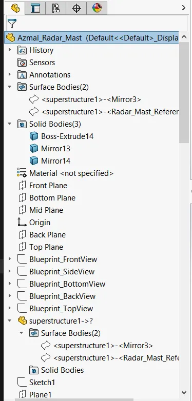
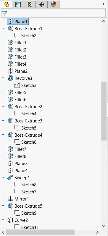
Features and Tools used to create Radar Mast
- Sketch ( Spline, Line,Circle)
- Extruded Boss
- Revolve
- Projected curve
- Mirror
- Fillet
- Chamfer
- Shell
- Appearances
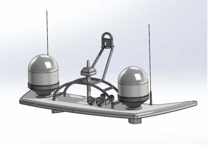
Figure 18- 3D Model of Radar Mast
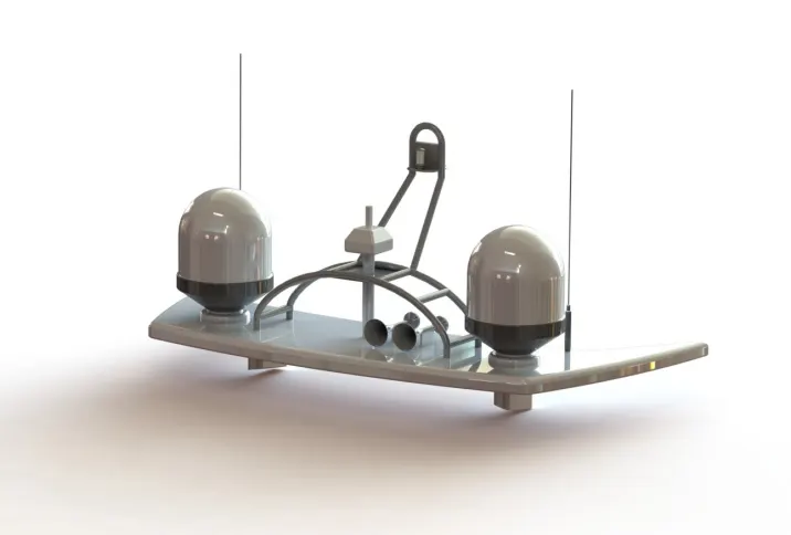
Figure 19- Rendering Model of Radar Mast
ASSEMBLY OF SUNSEEKER PREDECTOR YACHT
- The term mechanical assembly is most often referred to putting components together in an assembly line, but more specifically, it refers to creating a complete product that performs an intended function.
- In an assembly model, components are brought together to define a larger complex product representation. Assembly modelling is a tool that allows and facilitates the collaboration among designers, analysis people, manufacturing people and others to insure their assembly work together.
- You can build simple assemblies as well as complex assemblies consisting of many components, which can be parts or other assemblies, called sub-assemblies.
- For most operations, the behaviour of components is the same for both types. Adding a component to an assembly creates a link/mates between the assembly and the component.
- When SOLIDWORKS opens the assembly, it finds the component file to show it in the assembly.
- Changes in the component are automatically reflected in the assembly i,e. the rebuild option will automatically take place or else it will ask the user to rebuild the document.
- The document name extension for assemblies is “.sldasm”.
- Mates creates geometric relationships between assembly components. As you add mates, you define the allowable directions of linear or rotational motion of the components. You can move a component within its degrees of freedom, visualizing the assembly's behavior.
- The assembly of the yacht consist of all the parts attached in appropriate manner with proper mates such as coincident, concentric, perpendicular, tangent and distance mates.
- The main component is first fixed and other parts are mated with respect to its position.
Assembly Approaches in Solidworks:
- Top-Down Approach
- Bottom-up Approach
- Top-Down Approach
- In Top-Down design, parts, shapes, sizes, and locations can be designed in the assembly environment itself.
- The advantage of the top-down design is that much less rework is needed when design change occur.
- The parts know how to update themselves based on the way you created them i.e, by using an external reference such as converted entities etc.
- You can use top-down approach techniques on certain features of the part, complete parts or entities assemblies.
- In practice, designers typically use top-down techniques to layout their assemblies and to capture key aspects of custom parts specific to their assemblies.
- Bottom-Up Approach
- Bottom-up design is the traditional method. You will first design and model parts individually, then insert them into an assembly and use mates to position the parts. To change the parts, you must edit them individually. These changes are then seen in the assembly.
- Bottom-up design is the preferred technique for previously constructed, off-the shelf parts, or standard components like hardware, pulleys, motors,etc. These parts do not change their shape and size base on your design unless you choose a different component.
- If there is any interference in assembly or changes required in the assembly you need to modify the components individually either in the assembly level or parts document level.
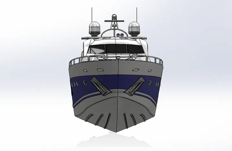
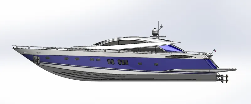
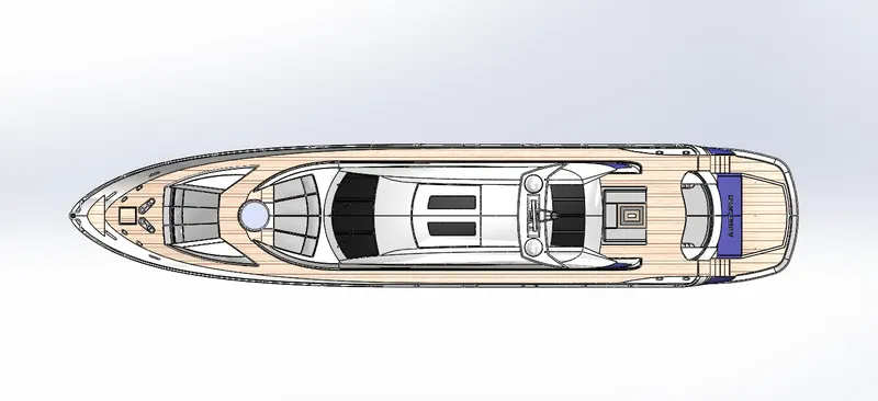
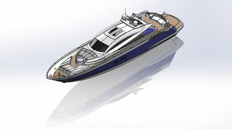
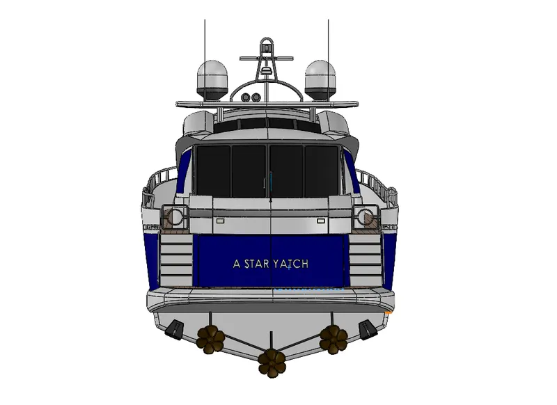
The following figure shows different views of Sunseeker Predector Yacht such as Front view, Top view, Side view and Isometric view.
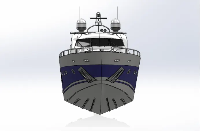
Figure 20- Front View of Sunseeker Predector Yacht
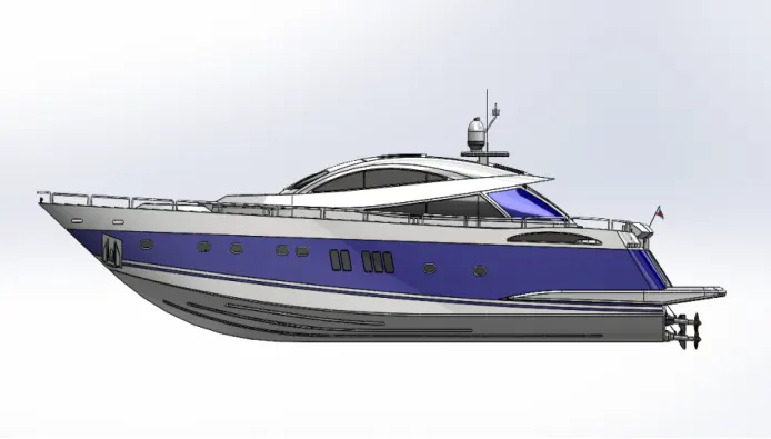
Figure 21- Side View of Sunseeker Predector Yacht
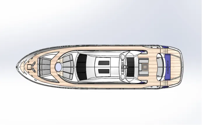
Figure 22- Top View of Sunseeker Predector Yacht
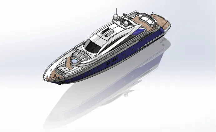
Figure 23- Isometric View of Sunseeker Predector Yacht
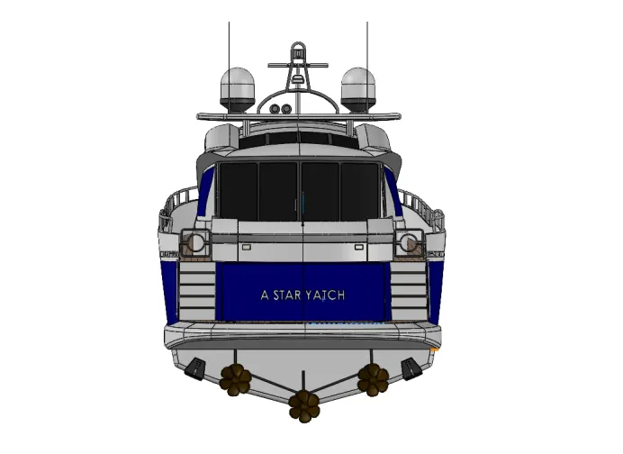
Figure 24-Back view of Sunseeker Predector Yacht
RENDERING OF AMERICAN CHOPPER MOTORCYCLE
- Rendering is the process of creating realistic images of the photo-realistic model with the environment.
- Rendering of the model is done using PhotoView 360 and Solidworks Visualize.
- PHOTOVIEW 360
- PhotoView 360 is a virtualization and rendering solution included with SOLIDWORKS.
- Providing a highly interactive environment for viewing designs as well as for creating photo-realistic renderings that can be used to showcase your designs.
- Photo View 360 is a SOLIDWORKS add-in that produces photo-realistic renderings of SOLIDWORKS models.
- The rendered image incorporates the appearances, lighting, scene, and decals included with the model.
- Photo View 360 is available with SOLIDWORKS Professional or SOLIDWORKS Premium.
- PhotoView360 creates realistic images directly from the Solidworks models.
- PhotoView360 interacts with the 3D geometry created with Solidworks. All changes to Solidworks models are accurately represented in the PhotoView360 images.
Procedure for Rendering the model
- With a model open, click Tools > Add-In and add in Photo View 360.
- Start a preview in the graphics area or open the preview window to see how changes you make to the model affect the rendering.
- Edit appearnce, the scene, and decals.
- Edit lights.
- By default, lighting is off in Photo View. With lights off, you can use the realistic lighting provided by scenes, which is usually sufficient for rendering. You typically need additional lighting in Photo View to illuminate occluded spaces in the model.
- Edit photo view option.
- When you are ready, perform a final render either now (Photo View > Final Render) or later (Photo View > Schedule Render).
- If annotations or dimensions are visible in your model, a dialog box appears with options to include the dimensions and annotations or render without them.
- If you have not added a camera or turned-on perspective view, which provide more realistic, higher quality renderings, a dialog box appears. You can turn on a camera or perspective view from the dialog box or continue without them.
- Make detailed adjustments in the Final Render Window.
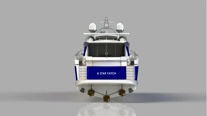
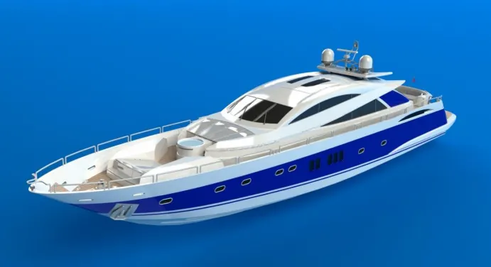
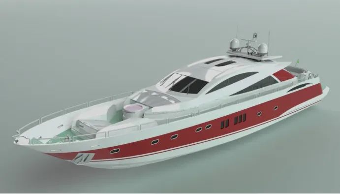
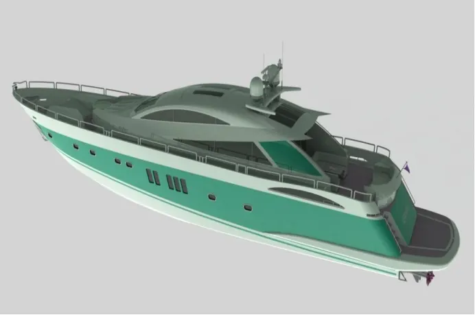
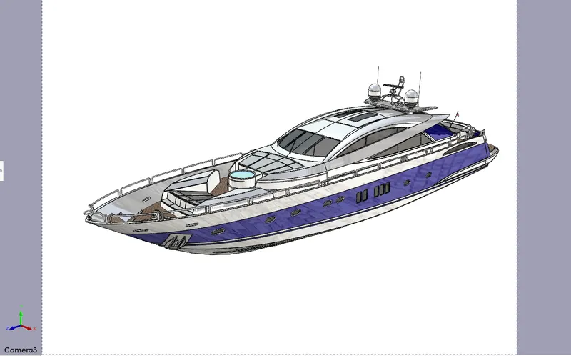
- Below figures show the rendering images of the Sunseeker Predector Yacht using PhotoView 360.
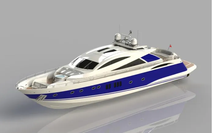
Figure 25- Rendering model of Sunseeker Predector Yacht
- SOLIDWORKS VISUALIZE
- It provides a suite of standalone software tools that combine industry-leading rendering capabilities with visual design oriented features and workflows, allowing easy and fast creation of visual content that communicate a design's vision , passion and emotion.
- It is a separate render engine that is provided under Solidworks Professional.
- SOLIDWORKS Visualize professional adds an array of features including animations, custom lighting, 360 interactive and much more.
- SOLIDWORKS Visualize professional provides highest level of detail and optimized render times.
- It helps in creating render images of the Solidworks models in Photo-realistic environment for marketing quality images with various option to tweak on the final image required as per the user.
- It uses either of the CPU /GPU or both as hybrid to render quality images .
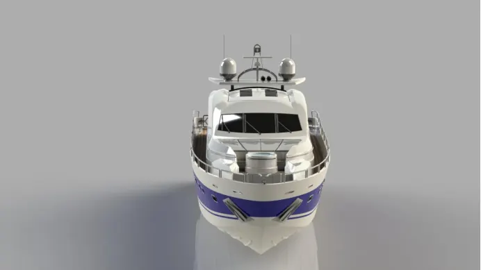
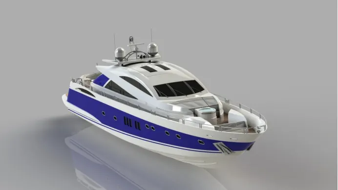
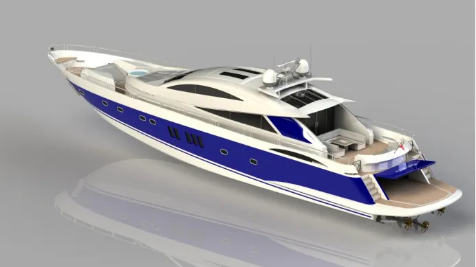
- Below figures show the rendering images of the Sunseeker Predector Yacht using SOLIDWORKS Visualize professional.
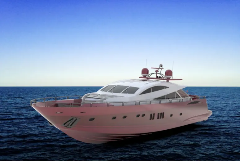
Figure 26- Rendering model of Sunseeker Predector Yacht
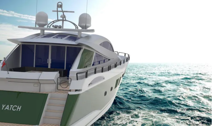
Figure 27- Rendering model of Sunseeker Predector Yacht
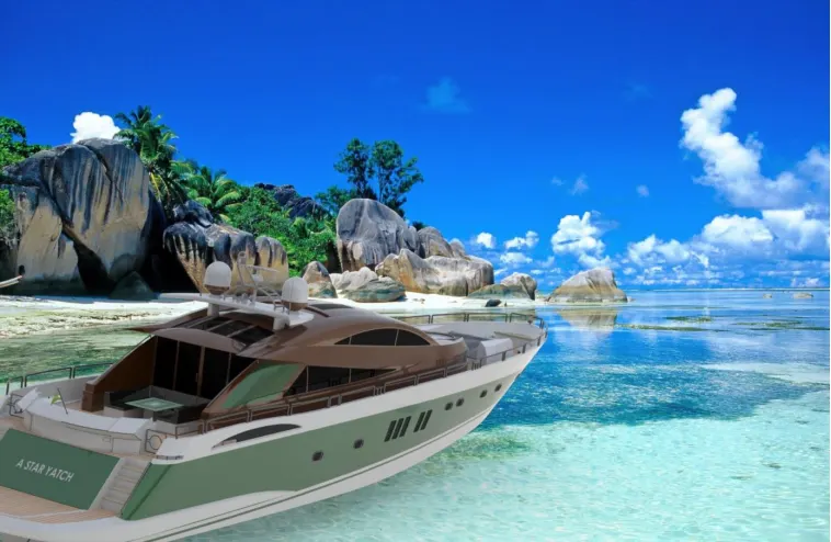
Figure 28- Rendering model of Sunseeker Predector Yacht
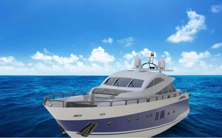
Figure 29- Rendering model of Sunseeker Predector Yacht
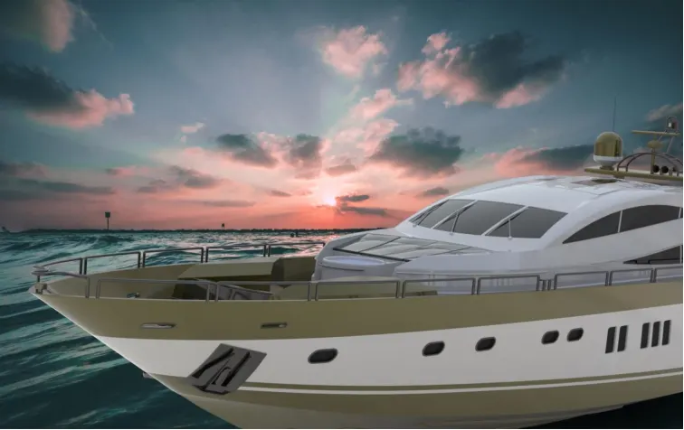
Figure 30- Rendering model of Sunseeker Predector Yacht
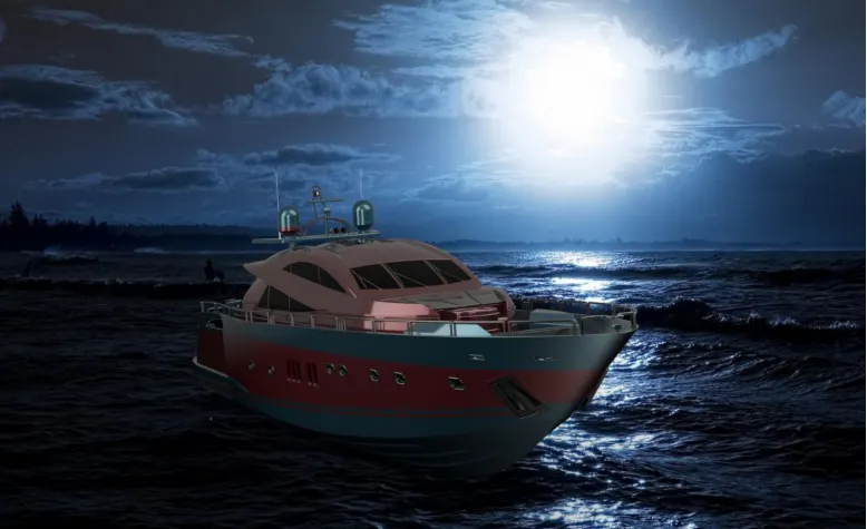
Figure 31- Rendering model of Sunseeker Predector Yacht
CONCLUSION
- Design and modelling of the parts of Yacht is modeled.
- Assembly of the Yacht is completed by inserting parts of Yacht with proper mating function.
- Photo realistic image of Sunseeker Predector Yacht is created with help of rendering software like PhotoView360 and SOLIDWORKS Visualize.
RADAR MAST PART
FRONT VIEW
RIGHT VIEW
TOP VIEW
ISOMETRIC VIEW
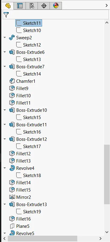
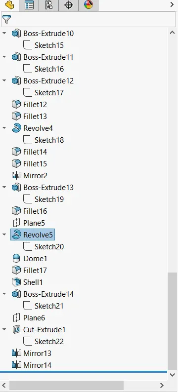
DESIGN FEATURE TREE
ASSEMBLY OF SUNSEEKER PREDECTOR YACHT
FRONT VIEW
RIGHT VIEW
TOP VIEW
ISOMETRIC VIEW
BACK VIEW
CAMERA VIEW
DESIGN TREE