Photo Realistic Rendering
ASSEMBLY IMAGES OF AMERICAN CHOPPER ASSEMBLY
1. FRONT VIEW OF AMERICAN CHOPPER ASSEMBLY
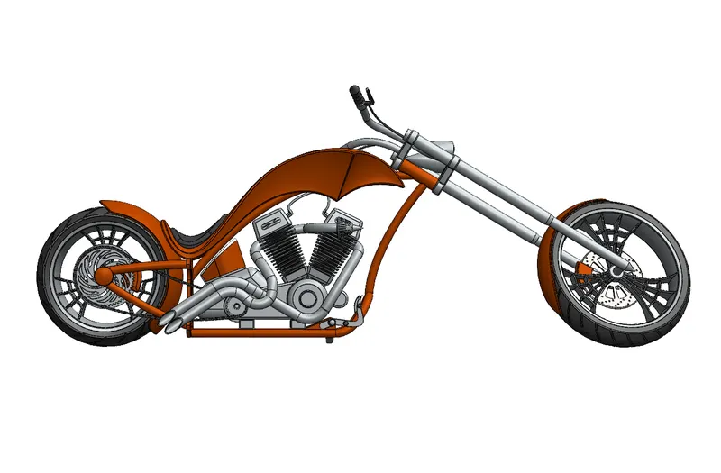
2. RIGHT VIEW OF AMERICAN CHOPPER ASSEMBLY
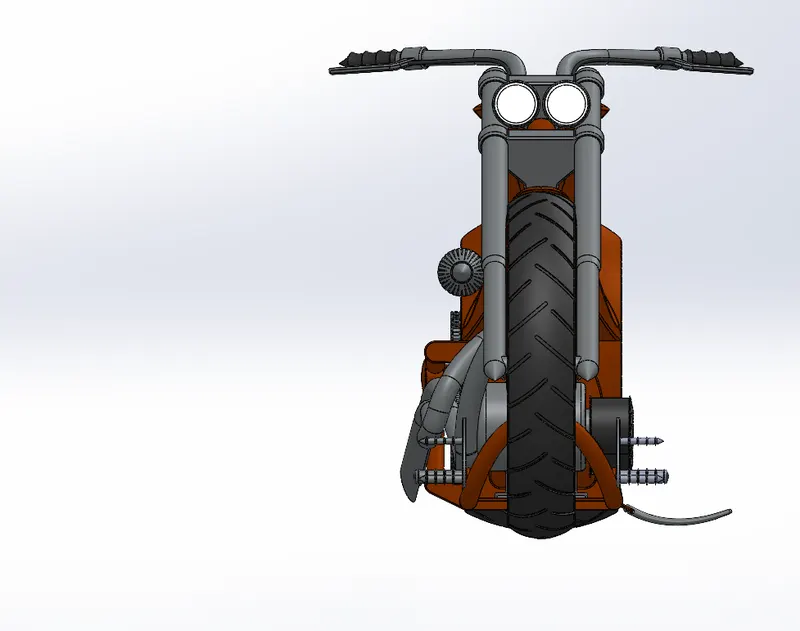
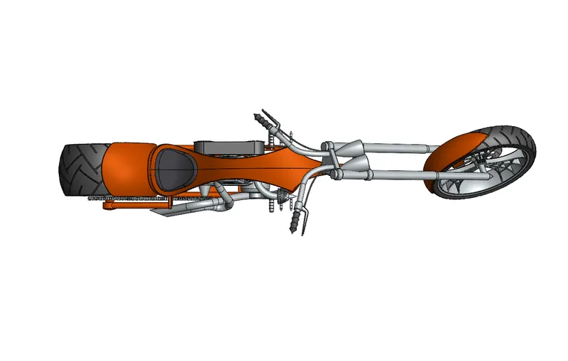
3. TOP VIEW OF AMERICAN CHOPPER ASSEMBLY
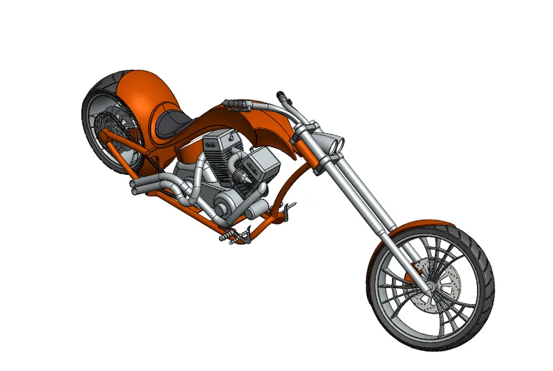
4. ISOMETRIC VIEW OF AMERICAN CHOPPER ASSEMBLY
5. CAMERA VIEW OF AMERICAN CHOPPER ASSEMBLY
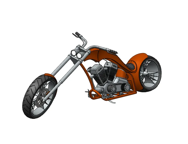
RENDERING IMAGES OF AMERICAN CHOPPER ASSEMBLY USING PHOTOVIEW360
1.RENDER IMAGE OF AMERICAN CHOPPER ASSEMBLY
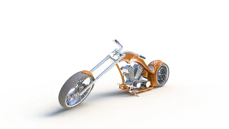
2.
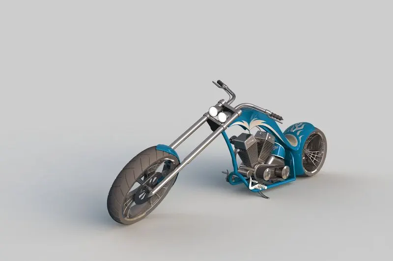
3.
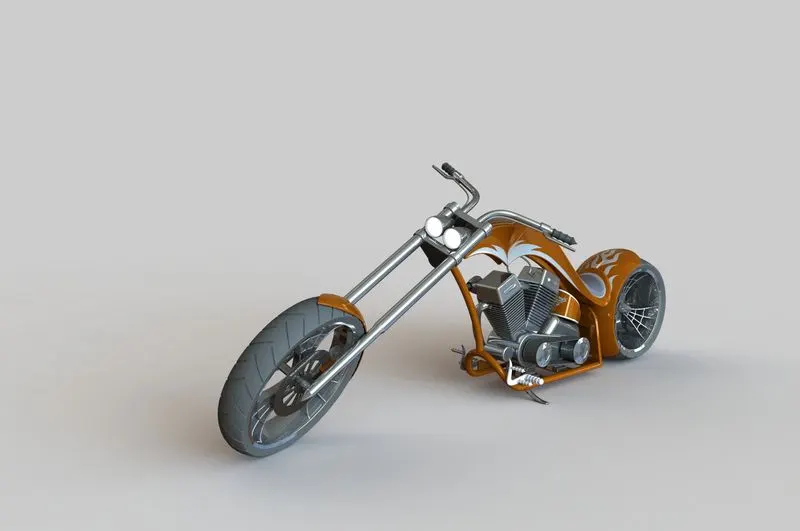
4.
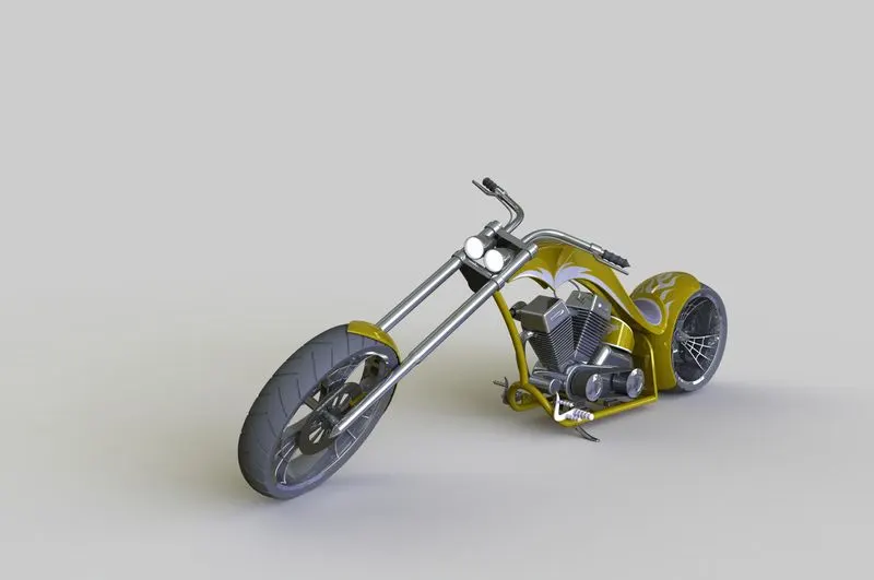
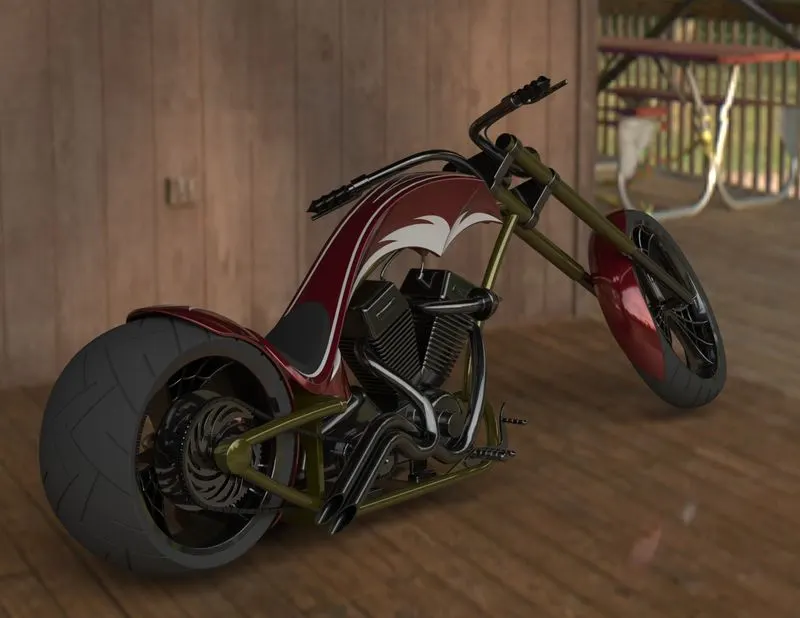
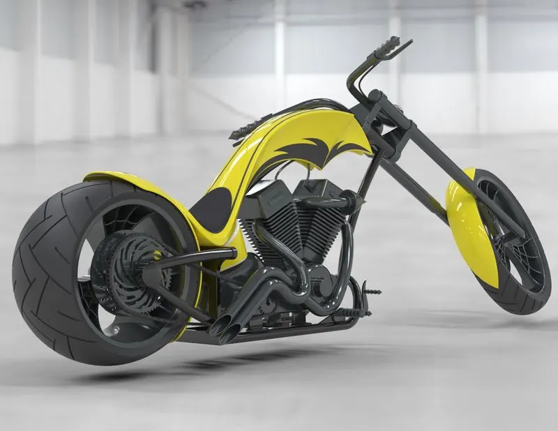
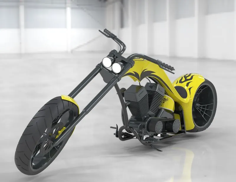
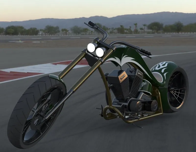
RENDERING IMAGES OF AMERICAN CHOPPER ASSEMBLY USING SOLIDWORKS VISUALIZE
1.
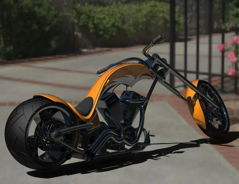
2.
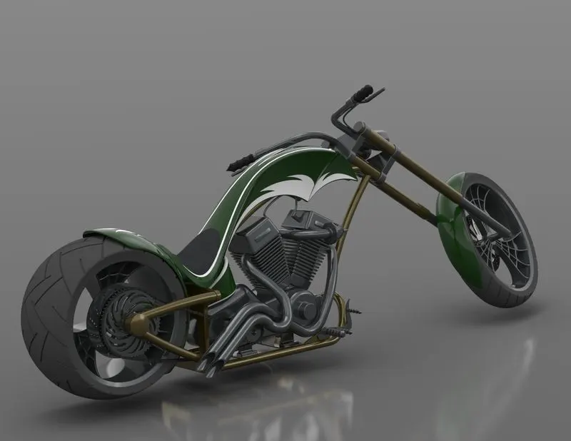
3.
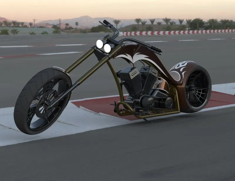
4.
5
6
7.
REPORT OF AMERICAN CHOPPER ASSEMBLY
Design and Assembly of American Chopper Motorcycle with Photo Realistic Rendering using SOLIDWORKS and SOLIDWORKS Visualize
OBJECTIVE
- Understand the Design and to Create 3D model of different parts of Chopper Motorcycle using SOLIDWORKS 3D modelling software.
- To assemble American Chopper Motorcycle by assembling sub-modeled parts of chopper using SOLIDWORKS 3D modelling software.
- To create Photo Realistic Rendering of the Chopper Motorcycle using Photo-View 360 and SOLIDWORKS Visualize Professional.
INTRODUCTION
SOLIDWORKS is a design automation software and it is published by Dassault System. It is a solid modelling software that allows to design products in three dimensions. It is computer aided design program which helps to draw any simple or complex mechanical shapes or assembling and drawing.
American Chopper Motorcycle built by Orange County Choppers(OCC) for a specific corporate or celebrity customer. The theme of the motorcycle takes priority over anything else,influencing the frame dimensions, paint scheme and overall fell of the motorcycle. The function of the motorcycle usually takes a backseat to the presentation of the theme and these motorcycle attract attention solely on the premise of the theme itself. The first chopper bike was built in America and tended to be based on Harley Davidson Motorcycles.
COMMANDS AND FEATURES USED
- General:- Sketch, Smart Dimension, 3D Sketch (line, rectangle, circle, spline, arc, polygon, fillet, ellipse), Offset Entities, Trim and Extend Entity, Convert Entity, Mirror Entities, Linear/Circular Pattern, Dynamic mirror.
- Solid Model:-Extruded Bose/Base, Revolved Bose/Base, Swept Bose/Base, Lofted Base/Boss, Extruded Cut, Swept Cut, Lofted Cut, Fillet, Chamfer, Circular &Linear Pattern, Shell, Dome ( Face dome/ elliptical dome), Split, Combine(Add/Subtract/Common).
- Surface Model:- Swept Surface, Lofted Surface, Boundary Surface, Filled Surface, Surface Trim, Extended Surface, Surface Knit, Offset Surface, Delete Face.
- Appearances:- Surface, Body and Part Colour.
|
Sketch |
It is the two dimensional representation of the model with respect to the plane/view from the outside of the model. In solidworks there are different sketch option available to create a sketch. These are known as entities in solidworks. |
|
Line |
Its is used to create line in solidworks. It can be normal line,construction or midpoint line. |
|
Rectangle |
It is used to create rectangle in solidworks. |
|
Circle |
It is used to create circular drawing on the graphics area. There are two circles available they are center circle and perimeter circle. |
|
Spline |
It is used to make line whose curvature can be adjusted. |
|
Tangent Arc |
An incomplete circle defined by its tangency to the sketch entity. |
|
Fillet |
It is used to make rounded faces internally or externally on the edges of the body/sketch |
|
Ellipse |
It is used to create complete ellipse |
|
Offset entities |
Copy a sketch entity to a specified distance from the original entity. |
|
Trim entities |
It is used to remove extra sketch or sketch which is not required |
|
Extend entities |
It is used to extend a sketch entity to meet another sketch entity that is too add extra length to the sketch entity (line,center-line or arc) |
|
Convert entities |
It is used to create one or more sketch by projecting an edge, loop,face,curve or external sketch contour onto the sketch plane. |
|
Mirror entities |
It is used to make a copy of the sketch along a reference axis/plane/line. |
|
Linear pattern |
It is used to make linear patterns for solid bodies or cuts along a reference line |
|
Circular pattern |
It is used make circular pattern for solid bodies or cuts along a reference axis of a circular reference geometry. |
|
Extruded Bose |
It is used to make 2D sketch into solid body |
|
Revolved Bose |
It is used to create solid body from sketch around an axis |
|
Extruded Cut |
It is used to cut through a solid body |
|
Revolved Cut |
It is used to create a cut in solid body around a revolve axis |
|
Swept |
It is used to make a solid body which follows a particular axis,known as swept axis. It is used for making uneven solid bodies. |
|
Swept Cut |
It is used to make cut along a swept axis in a solid body. |
|
Shell |
It is used to make a solid body hollow. |
|
Dome |
It is used to create a dome that is tangent to the adjacent cylindrical or conical faces. |
|
Split |
It is used to create multiple parts from an existing part. |
|
Chamfer |
It is used to make inclined faces on the edge of the solid body |
|
Loft |
It is used to add material between two ore profiles to make sold body |
|
Reference Geometry |
It is used for creating reference plane/axis |
|
Surface Knit |
It is used to knit the two free edges/open edges of the surface together. Also it reduces the gap between the two edges of the surface |
|
Boundary Surface |
It is used to make surface from the boundary |
DESIGN METHODOLOGY
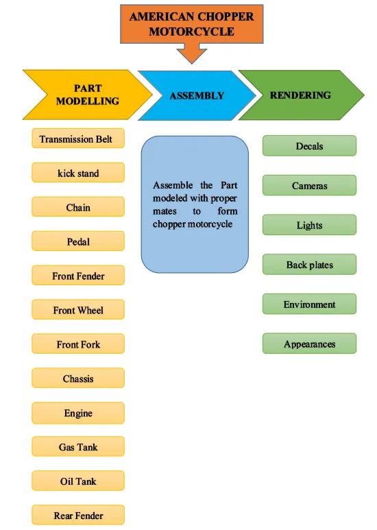
PART MODELLING OF CHOPPER MOTORCYCLE
- TRANSMISSION BELT
Description- Transmission Belt is used to transmit power from one end of the shaft/pulley to another. These belt are mainly made up of canvas material which are more flexible,long life with low maintenance cost. Transmission belt used in chopper to transfer the mechanical energy obtained from engine shaft to the transmission gears. Below figures indicates,
Figure1 : shows the 3D model of the transmission belt using SOLIDWORKS
Figure2: shows the Rendering image of transmission belt using Photo-view 360
Features and Tools used to create transmission belt
- Sketch
- Offset
- Extrude
- Fillet
- Appearances
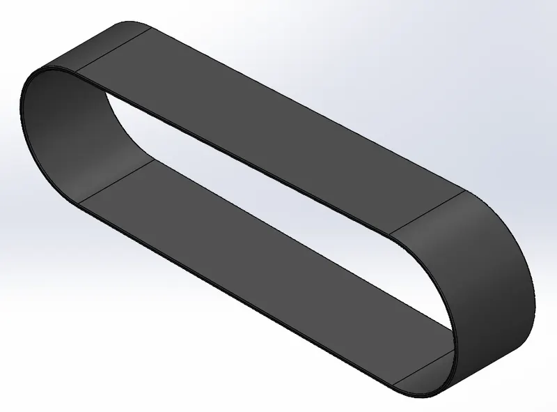
Figure 1- 3D Model of Transmission Belt
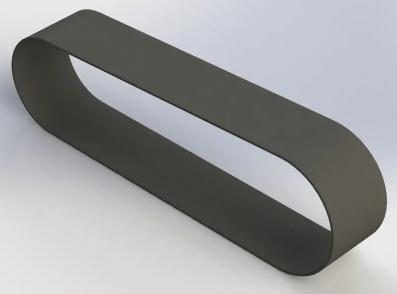
Figure 2- Rendering Model of Transmission Belt
- KICK STAND
Description- kick stand is a machine component that allows the motorcycle to be kept upright without leaning against other object. It is also know as side stand which act has high supportive strength to withstand load of chopper while in rest position. It is generally mounted on the left side bottom portion of the chassis. Below figures indicates,
Figure3 : shows the 3D model of the Kick Stand using SOLIDWORKS
Figure4: shows the Rendering image of Kick Stand using Photo-view 360
Features and Tools used to create kick Stand
- Sketch ( Ellipse, Spline)
- Loft
- Dome
- Extrude Bose
- Extrude cut
- Fillet
- Pierce
- Split
- Appearances
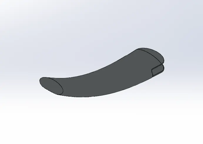
Figure 3- 3D Model of Kick-stand
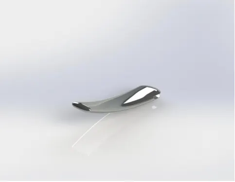
Figure 4- Rendering Model of Kick-stand
- CHAIN
Description- Chain is the type of transmission system that is used to transmit a power from Engine to Rear Wheel. Most of the Chains are made from plain carbon and alloy steel. The chain fits onto sprocket teeth of both small and large sprocket. Sprocket is used to transmit power to the chain.Below figures indicates,
Figure5 : shows the 3D model of the Chain using SOLIDWORKS
Figure6: shows the Rendering image of Chain using Photo-view 360
Features and Tools used to create kick Stand
- Sketch ( Circle, 3 Point-Arc)
- Trim
- Extrude Bose
- Blocks
- Fillet
- Curve driven Pattern
- Mirror
- Appearances
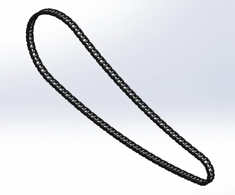
Figure 5- 3D Model of Chain
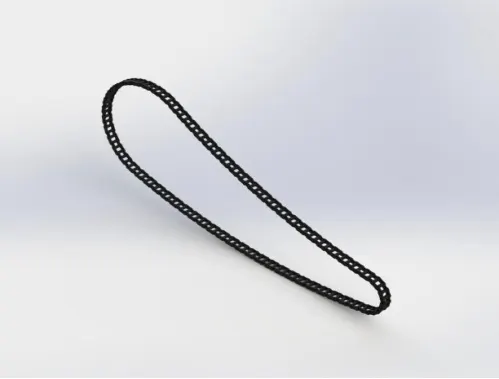
Figure 6- Rendering Model of Chain
- PEDAL
Description- Pedal is also knows as foot rest which is mounted on both sides of motorcycle in order to rest the foot of the rider while riding. Brakes and gear shift pedal are also located at each side of the pedal. In Chopper type motorcycle, pedals are designed and mounted on front side of the chassis to get comfortable while riding.Below figures indicates,
Figure7 : shows the 3D model of the Pedal using SOLIDWORKS
Figure8: shows the Rendering image of Pedal using Photo-view 360
Features and Tools used to create Pedal
- Sketch ( Circle, Line,Spline)
- Revolve Bose
- Extrude Bose
- Fillet
- Dome
- chamfer
- Linear Pattern
- Mirror
- Appearances
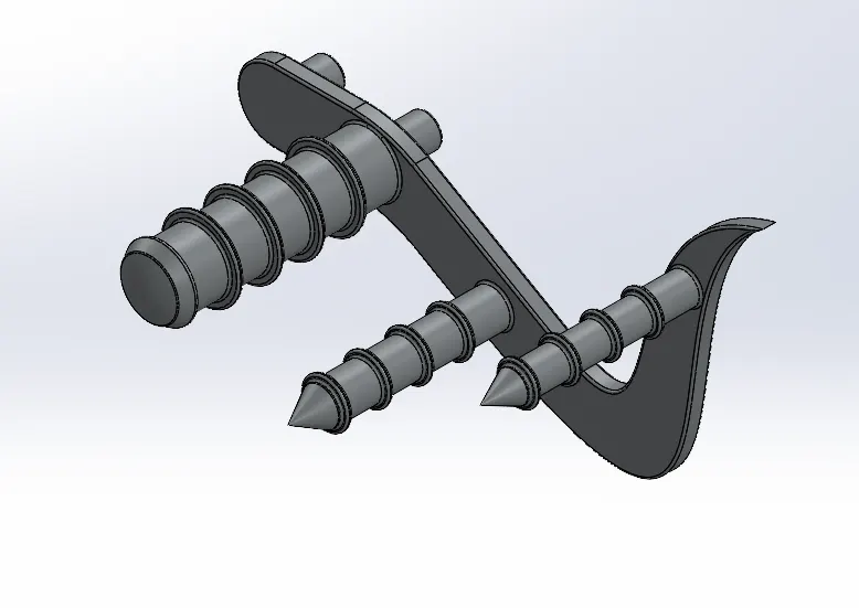
Figure 7- 3D Model of pedal
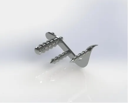
Figure 8- Rendering Model of pedal
- FRONT FENDER
Description- Fender also called as mudguards. It is used to protect the rider and motorcycle from mud, sand, liquid and other foreign particles from being thrown into the air while rotating Tyre. Front fender is placed as a protecting cover on the upper side of Front wheel.Below figures indicates,
Figure9 : shows the 3D model of the Front Fender using SOLIDWORKS
Figure10: shows the Rendering image of Front Fender using Photo-view 360
Features and Tools used to create Front Fender
- Sketch ( 3 point Arc, Spline)
- Revolve Bose
- Extended Entities
- Offset Entities
- Trim Entities
- Fillet
- Split
- Appearances
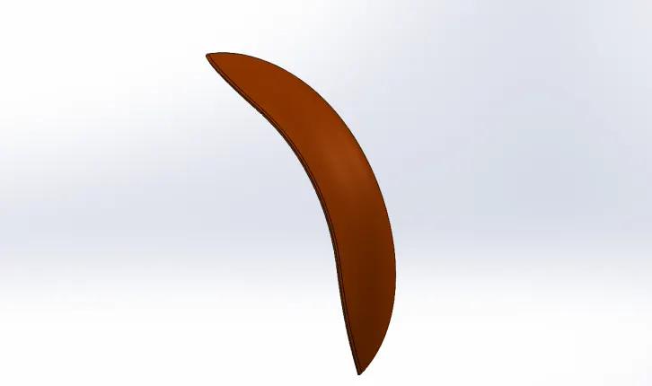
Figure 9- 3D Model of Front Fender
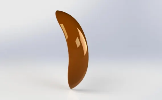
Figure 10- Rendering Model of Front Fender
- FRONT WHEEL
Description- Motorcycle wheels plays a major role to move the vehicle .It is made to cope with radial and axial forces. In chopper, spider webbed spoke wheel is used. It consist of rim, rotor , calliper with pneumatic Tyre. Spoke are the connecting rods between hub and rim which distributes the loads between them. Tyre are main contact surface to the ground. Front wheel of chopper are large in diameter which gives better stability to motorcycle and handle in possible rough roads that protects rest of the motorcycle.Below figures indicates,
Figure11 : shows the 3D model of the Front Wheel using SOLIDWORKS
Figure12: shows the Rendering image of Front Wheel using Photo-view 360
Features and Tools used to create Front Wheel
- Sketch ( 3 point Arc, Spline, Line, Circle, Fillet)
- Extended Entities
- Offset Entities
- Trim Entities
- Revolve Bose
- Extrude cut
- Revolved cut
- Circular pattern
- Chamfer
- Fillet
- Appearances
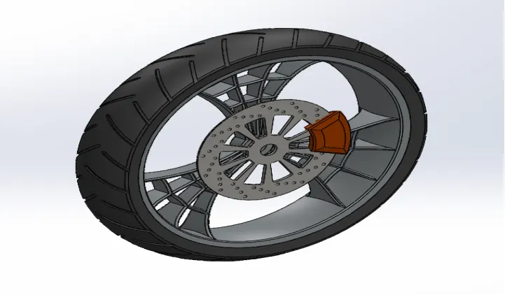
Figure 11- 3D Model of Front Wheel
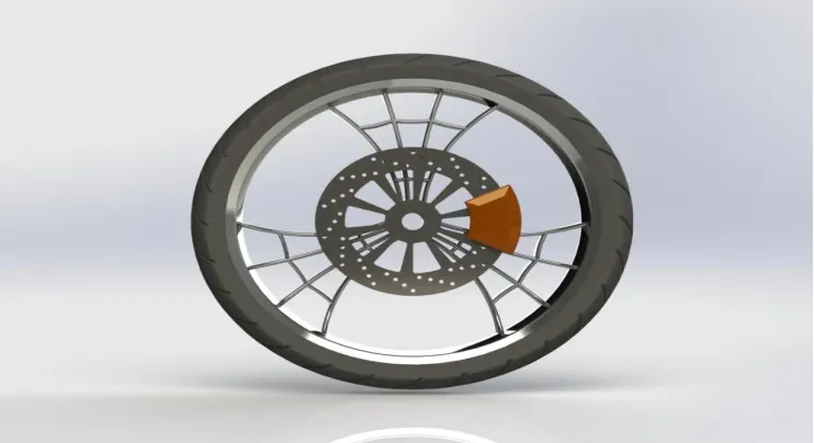
Figure 12- Rendering Model of Front Wheel
- FRONT FORK
Description- The main function of motorcycle fork is to connect front wheel of motorcycle and axle to its frame through yoke which is also known as triple clamp. Triple clamp consist of two parts upper yoke joined with lower yoke that connects the steering stem to rotate handle and front wheel. Most of the motorcycle use telescopic fork as front suspension that consist of spring and oil inside the tube. When there is imbalance in the roads front wheel allow the front fork to move up and down as result spring act as shock absorber while oil moves around the tubes and springs to keep things lubricated and function smoothly.
Front fork of motorcycle houses with sub components like headlight, handle grips, handle bars,brake and clutch lever, cables, switches and axle.Below figures indicates,
Figure13 : shows the 3D model of the Front Fork using SOLIDWORKS
Figure14: shows the Rendering image of Front Fork using Photo-view 360
Features and Tools used to create Front Fork
- Sketch ( Spline, Line, Circle)
- Revolve Bose
- Extrude cut
- Revolved cut
- Reference plane
- Reference axis
- Fillet
- Mirror
- Dome
- Linear pattern
- Swept boss/base
- Combine
- Project curve
- Trim Entities
- Move/ copy body
- Appearances
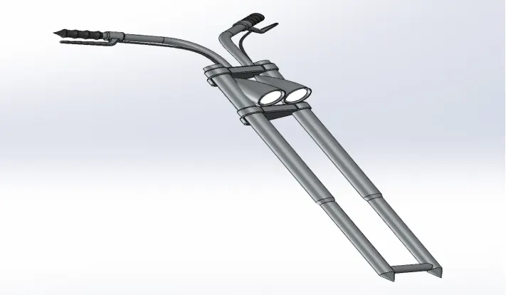
Figure 13- 3D Model of Front Fork
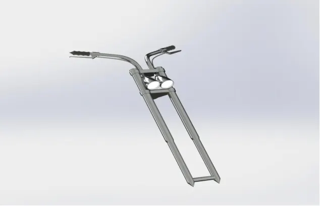
Figure 14- Rendering Model of Front Fork
- CHASSIS
Description- Chassis is main supporting structure of the motorcycle also known as “ Structural Frame”. The structural supporting frame is made up of high strength material which can withstand load of the vehicle body and all the variable stresses on the vehicle both static and dynamically. Like human spine and supporting skeleton, motorcycle chassis holds everything together as it provides space and mounting location for different components like engine, suspensions, wheels, oil tanks,fuel tanks, handle bars, seats etc, that leads the motorcycle its strength and ability to handle well.Below figures indicates,
Figure15 : shows the 3D model of the Chassis using SOLIDWORKS
Figure16: shows the Rendering image of Chassis using Photo-view 360
Features and Tools used to create Chassis
- Sketch ( Spline, Arc,Line)
- Revolve Boss/ Base
- Extrude Boss/ Base
- Swept Boss/ Base
- Project curve
- Extrude cut
- Reference geometry
- Fillet
- Chamfer
- Mirror
- Split
- Dome
- Combine
- Trim Entities
- Appearances
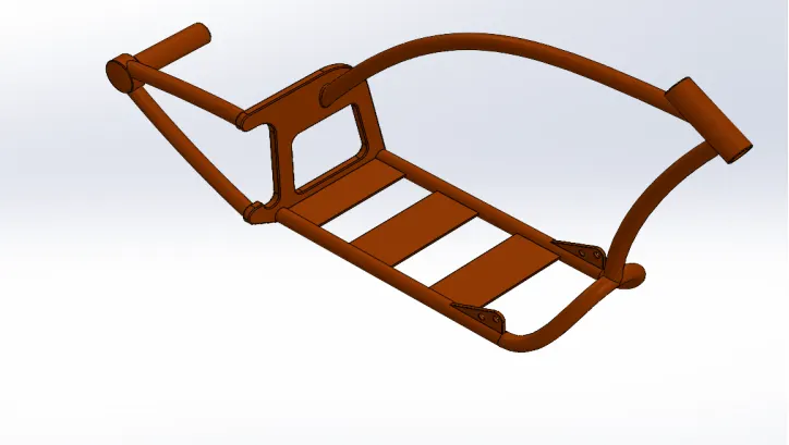
Figure 15- 3D Model of Chassis
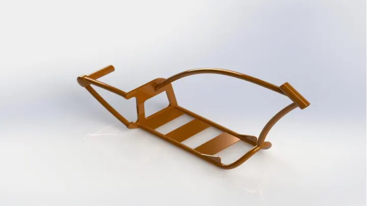
Figure 16- Rendering Model of Chassis
- ENGINE
Description- Engine is the main core of the motorcycle. Engine converts chemical energy into heat energy and then to mechanical energy. Generally motorcycle engines are internal combustion spark ignition type that consist of inlet and outlet ports and also piston-cylinder arrangement which drives the motorcycle. In IC engine the combustion of Air-fuel mixture pushes the piston up and down to rotate the crankshaft, thus the energy from piston is transferred into rotary motion. The rotary motion of the crankshaft is then transmitted to real wheel with the help of gearbox and chain sprocket mechanism to drive the motorcycle. In American Chopper V-Twin engine is used consist of air filter, spark plug for each cylinder, air cooling fins, transmission pulleys, front sprocket for chain drive, motor and exhaust pipes. Below figures indicates,
Figure17 : shows the 3D model of the Engine using SOLIDWORKS
Figure18: shows the Rendering image of Engine using Photo-view 360
Features and Tools used to create Engine
- Sketch ( Spline, Line, Circle, arc)
- Composite curve
- Circular pattern
- Extruded Boss/ Base
- Revolve Boss/ Base
- Extrude cut
- Reference geometry
- Fillet
- Chamfer
- Mirror
- Dome
- Split
- Offset
- Combine
- Project curve
- Trim Entities
- Appearances
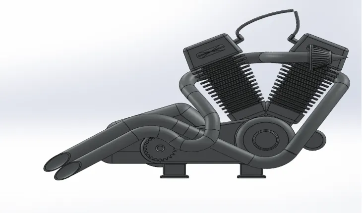
Figure 17- 3D Model of Engine
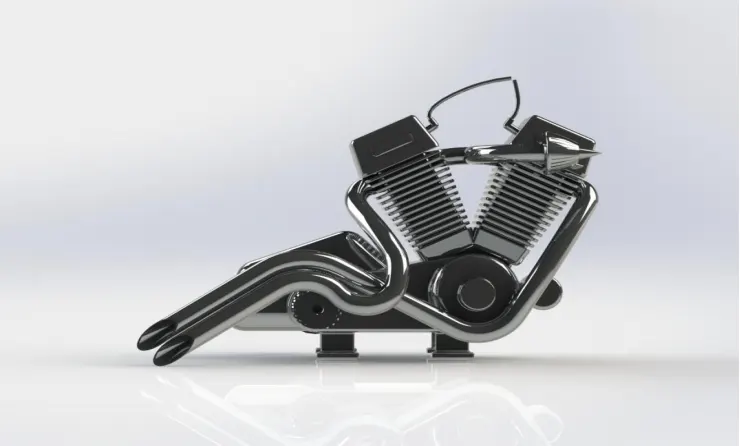
Figure 18- Rendering Model of Engine
- GAS TANK
Description- Gas tank or Fuel tank is the closed container with sufficient volume to store the flammable fluids in a cool state away from the engine heat. The safety of the flammable fluids are the main criteria in designing the fuel tank. The fuel tank is made out of plastic high-density polyethylene which can made into complex shape, save space, and can improve crash safety. It can also be made out of steel or aluminium which is welded from stamped sheets. Below figures indicates,
Figure19 : shows the 3D model of the Gas tank using SOLIDWORKS
Figure20: shows the Rendering image of Gas tank using Photo-view 360
Features and Tools used to create Gas tank
- Sketch ( Spline, Line, Arc)
- Extruded Surface
- Swept Surface
- Knit Surface
- Surface Boundary
- Surface Trim
- Lofted Surface
- Project curve
- Convert Entities
- Mirror
- Fillet
- Extrude cut
- Shell
- Appearances
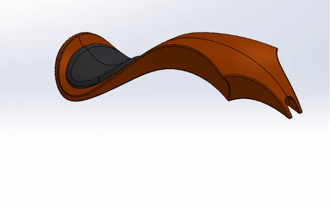
Figure 19- 3D Model of Gas Tank
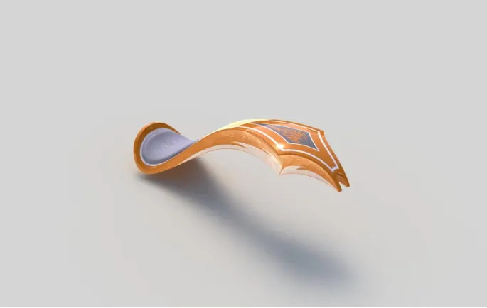
Figure 20- Rendering Model of Gas Tank
- OIL TANK
Description- Oil Tank is the component used to store oil for lubrication and cooling purpose of the engine components. In American chopper, Engine has dry sump system. In order to maintain internal temperature inside the engine cylinder, oil tank is placed just below the seat to lubricate the engine components by constantly pumping the oil with the help of oil pump. Below figures indicates,
Figure 21 : shows the 3D model of the Oil Tank using SOLIDWORKS
Figure 22: shows the Rendering image of Oil Tank using Photo-view 360
Features and Tools used to create Oil Tank
- Sketch ( Line, 3-point arc)
- Extruded Boss/ Base
- Shell
- Fillet
- Combine
- Appearances
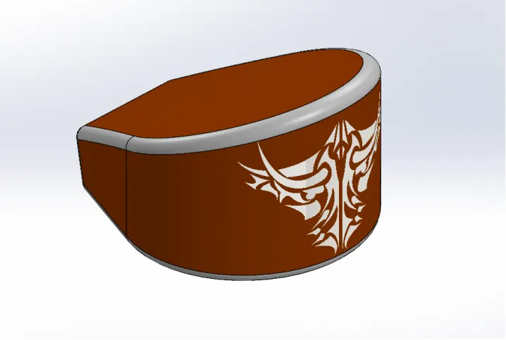
Figure 21- 3D Model of Oil Tank
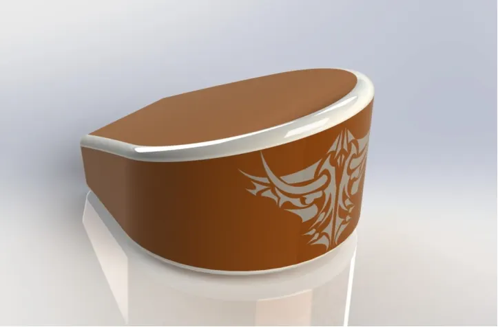
Figure 22- Rendering Model of Oil Tank
- REAR FENDER
Description- Rear Fender also called as mudguards. Rear fender is placed as a protecting cover on the upper side of Rear wheel. The primary function of the rear fender is to protect the rider and motorcycle from mud, sand, liquid and other foreign particles from being thrown into the air while rotating Tyre. Below figures indicates,
Figure 23 : shows the 3D model of the Rear Fender using SOLIDWORKS
Figure 24: shows the Rendering image of Rear Fender using Photo-view 360
Features and Tools used to create Rear Fender
- Sketch ( 3 point Arc, Spline)
- Revolve Bose
- Extended Entities
- Offset Entities
- Trim Entities
- Fillet
- Shell
- Appearances
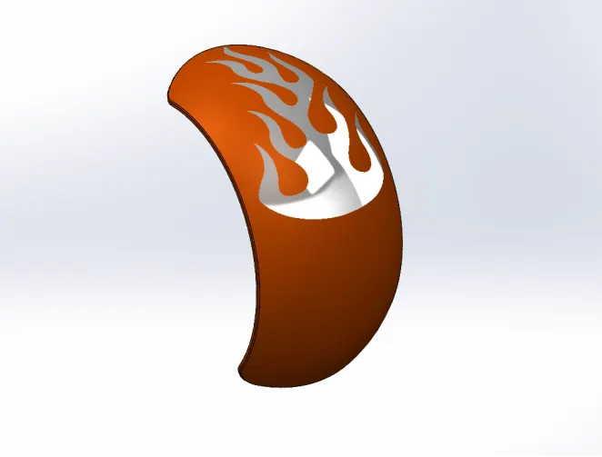
Figure 23- 3D Model of Rear Fender
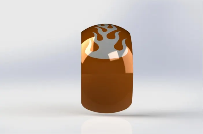
Figure 24- Rendering Model of Rear Fender
- REAR WHEEL
Description- Motorcycle wheels plays a major role to move the vehicle. The power from the engine is transmitted to the rear wheel through chain drive mechanism. In chopper, spider webbed spoke wheel is used. Spoke are the connecting rods between hub and rim which distributes the loads between them. It consist of rim, rotor, calliper with pneumatic Tyre that makes contact surface between motorcycle and the ground. The Rim is the important component of the motorcycle that ensures load carrying capacity of the bike. It is made out of high compressive strength material that absorbs shock and impacts while riding the motorcycle. Rear wheel of chopper are smaller in diameter than the front wheel having broader surface contact that can carry heavy loading capacity and for greater grip. Below figures indicates,
Figure 25 : shows the 3D model of the Rear Wheel using SOLIDWORKS
Figure 26: shows the Rendering image of Rear Wheel using Photo-view 360
Features and Tools used to create Rear Wheel
- Sketch ( 3 point Arc, Spline, Line, Circle, Fillet)
- Extended Entities
- Offset Entities
- Trim Entities
- Convert Entities
- Intersection curve
- 3-point centre rectangle
- Extruded Boss/Base
- Revolved Boss/Base
- Extrude cut
- Revolved cut
- Circular pattern
- Linear pattern
- Chamfer
- Fillet
- Appearances
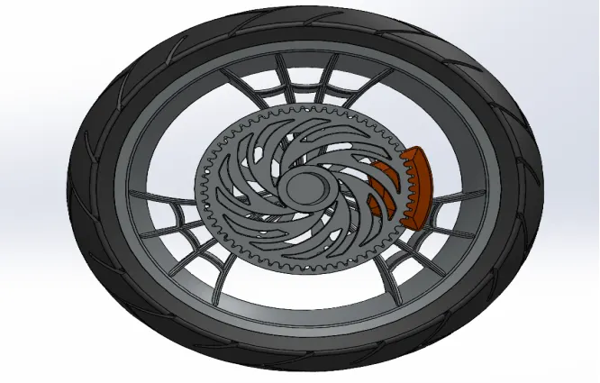
Figure 25- 3D Model of Rear Wheel
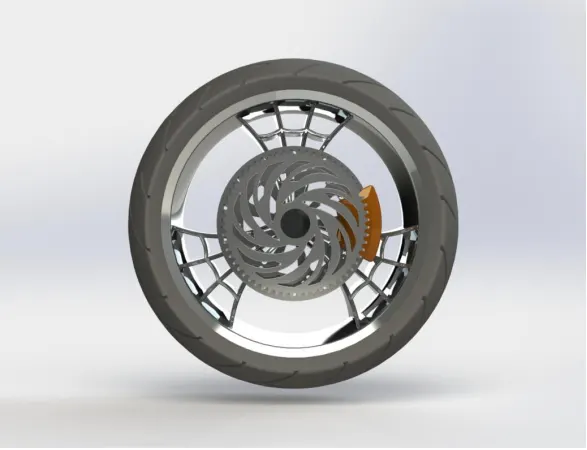
Figure 26- Rendering Model of Rear Wheel
ASSEMBLY OF AMERICAN CHOPPER MOTORCYCLE
In an assembly model, components are brought together to define a larger complex product representation. Assembly modelling is a tool that allows and facilitates the collaboration among designers, analysis people, manufacturing people and others to insure their assembly work together.
- Assembly -An assembly is a collection of two or more components, which can be parts or other assemblies called sub assemblies. An assemvbly is a part file that contains component objects.
- Sub assembly- A subassembly is an assembly that is used as a component object within a higher level assembly. A subassembly contains component objects of its own.
- Mates -Mates creates geometric relationships between assembly components. As you add mates, you define the allowable directions of linear or rotational motion of the components. You can move a component within its degrees of freedom, visualizing the assembly's behavior.
- The assembly of the chopper consist of all the parts attached in appropriate manner with proper mates such as coincident, concentric, perpendicular, tangent and distance mates.
- The main component is first fixed and other parts are mated with respect to its position.
- The following figure shows different views of American Chopper Motorcycle such as Front view, Top view, Side view and Isometric view.
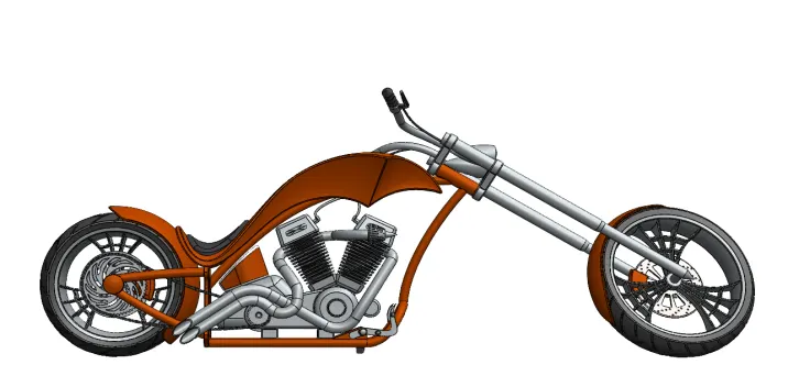
Figure 27- Front View of American Chopper Motorcycle
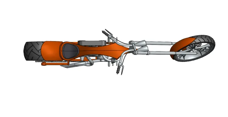
Figure 28- Top View of American Chopper Motorcycle
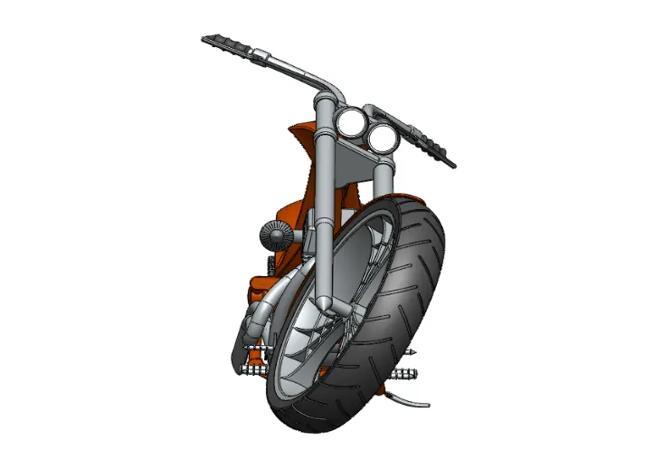
Figure 29- Right View of American Chopper Motorcycle
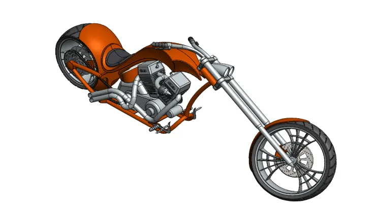
Figure 30- Isometric View of American Chopper Motorcycle
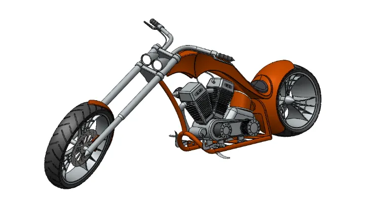
Figure 31- Camera view of American Chopper Motorcycle
RENDERING OF AMERICAN CHOPPER MOTORCYCLE
- Rendering is the process of creating realistic images of the photo-realistic model with the environment.
- Rendering of the model is done using PhotoView 360 and Solidworks Visualize.
- PHOTOVIEW 360
- PhotoView 360 is a virtualization and rendering solution included with SOLIDWORKS.
- Providing a highly interactive environment for viewing designs as well as for creating photo-realistic renderings that can be used to showcase your designs.
- PhotoView360 creates realistic images directly from the Solidworks models.
- PhotoView360 interacts with the 3D geometry created with Solidworks. All changes to Solidworks models are accurately represented in the PhotoView360 images.
- Below figures show the rendering images of the American Chopper Motorcycle using PhotoView 360.
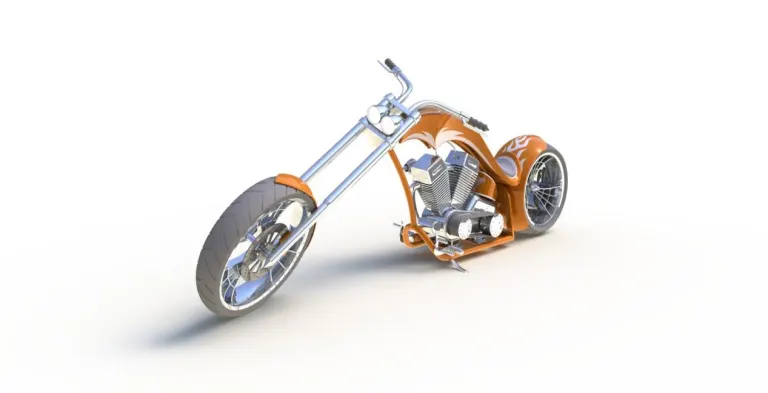
Figure 32- Rendering model of American Chopper Motorcycle
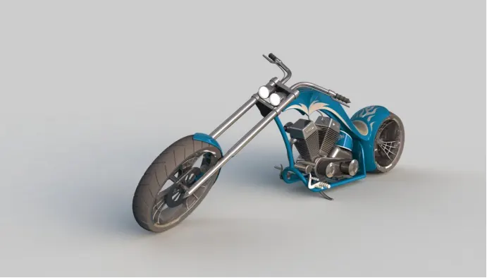
Figure 33- Rendering model of American Chopper Motorcycle
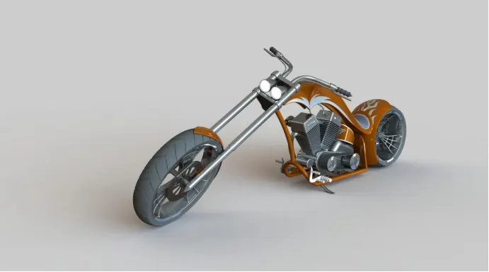
Figure 34- Rendering model of American Chopper Motorcycle
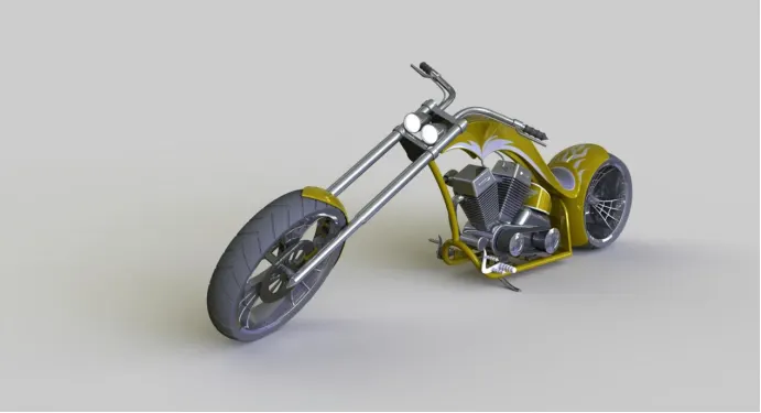
Figure 35- Rendering model of American Chopper Motorcycle
- SOLIDWORKS VISUALIZE
- It provides a suite of standalone software tools that combine industry-leading rendering capabilities with visual design oriented features and workflows, allowing easy and fast creation of visual content that communicate a design's vision , passion and emotion.
- It is a separate render engine that is provided under Solidworks Professional.
- SOLIDWORKS Visualize professional adds an array of features including animations, custom lighting, 360 interactive and much more.
- SOLIDWORKS Visualize professional provides highest level of detail and optimized render times.
- It helps in creating render images of the Solidworks models in Photo-realistic environment for marketing quality images with various option to tweak on the final image required as per the user.
- It uses either of the CPU /GPU or both as hybrid to render quality images .
- Below figures show the rendering images of the American Chopper Motorcycle using SOLIDWORKS Visualize professional.
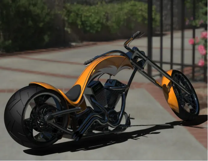
Figure 36- Rendering model of American Chopper using solidworks visualize
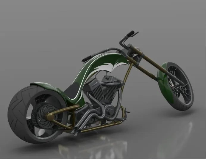
Figure 37- Rendering model of American Chopper using solidworks visualize
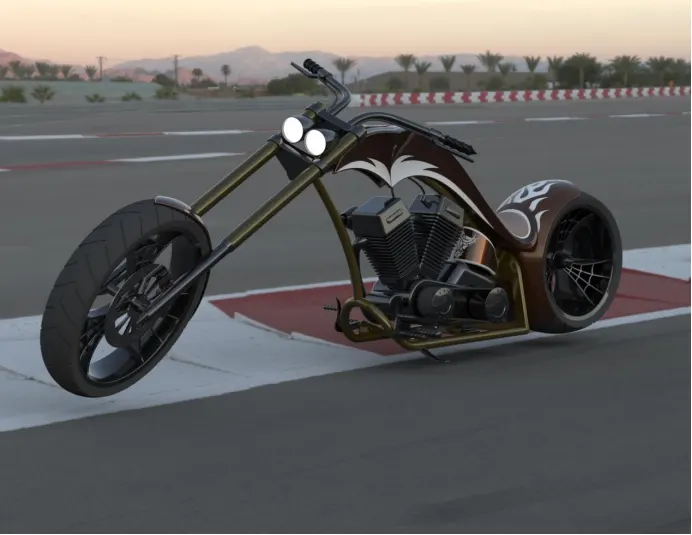
Figure 38- Rendering model of American Chopper using solidworks visualize
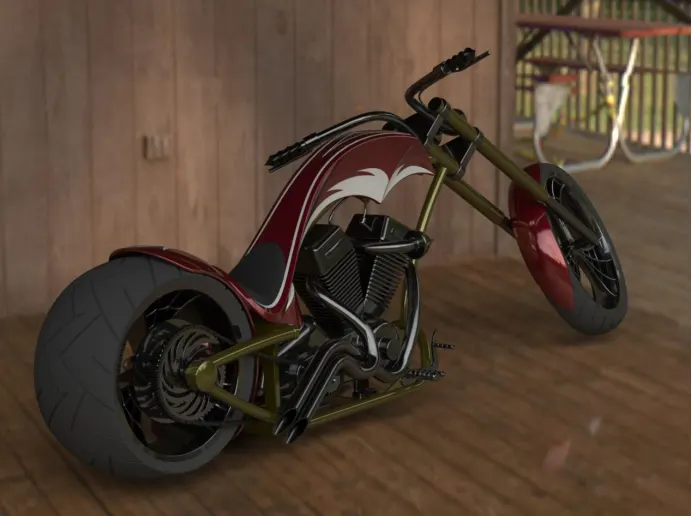
Figure 39- Rendering model of American Chopper using solidworks visualize
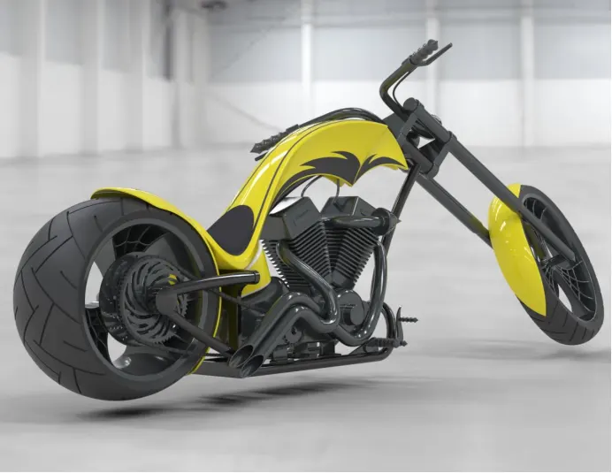
Figure 40- Rendering model of American Chopper using solidworks visualize
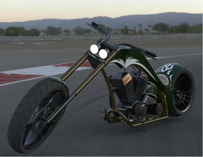
Figure 41- Rendering model of American Chopper using solidworks visualize
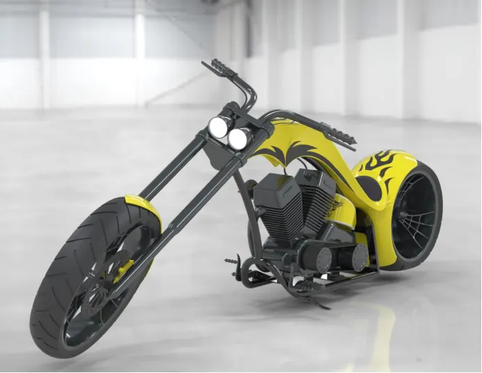
Figure 42- Rendering model of American Chopper using solidworks visualize
CONCLUSION
- Design and modelling of the parts of chopper is modeled.
- Assembly of the chopper is completed by inserting parts of chopper with proper mating function.
- Photo realistic image of American Chopper Motorcycle is created with help of rendering software like PhotoView360 and SOLIDWORKS Visualize.