Radar Mast & Final Assembly of Yacht
Radarmast
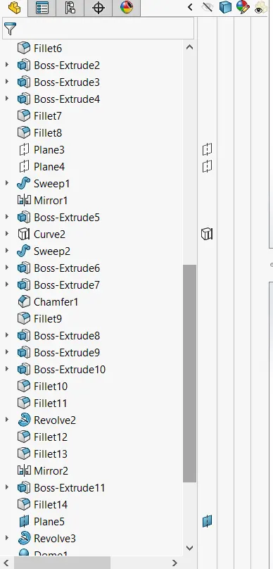
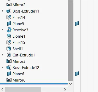
Assembly
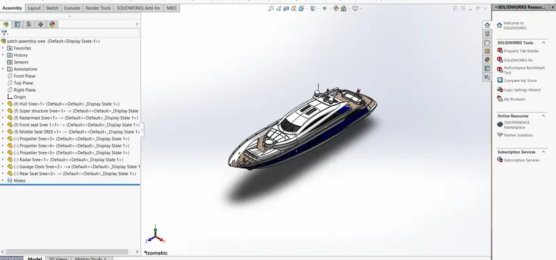
Report
MODELLING OF SUNSEEKER PREDATOR YACHT ON SOLIDWORKS
OBJECTIVE
- The main objective of the project is to sketch and build a complete " SUNSEEKER PREDATOR YACHT " using Solidworks.
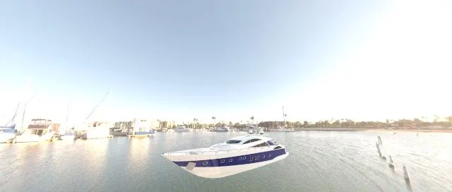
- To create a Photo realistic view of Yacht using Solidworks Photoview 360 and Solidworks Visualize.
INTRODUCTION
A Yacht is a sail or power vessel for pleasure, cruising, or racing. There is no standard definition, so the term applies touch vessel that have a cabin with amenities which accommodate overnight usage, luxurious cabin and all the necessities are perfectly loaded in a small power vessel. The name comes from the Dutch word yachtship, which originally meant hunting boat or fast boat.
COMPONENETS OF YACHT MODELLED IN SOLIDWORKS
- Propeller
- Radar
- Blueprint
- Hull
- Garage Door
- Front Seat
- Middle Seat
- Rear Seat
- Superstructure
- Radar Mast
BASIC DESCRIPTION OF PARTS AND THE FEATURE USED IN SOLIDWORKS
Propeller
The propeller is a rotating fan like structure which is used to propel the ship by using the power generated and transmitted by the main engine of the ship. It is a device with a rotating hub and radiating blades that are set at a pitch to form a helical spiral, that when rotated, perform an action which is similar to Archimedes screw. It transforms rotational power into linear thrust by acting upon a working fluid, such as water or air. The propeller is shown below,
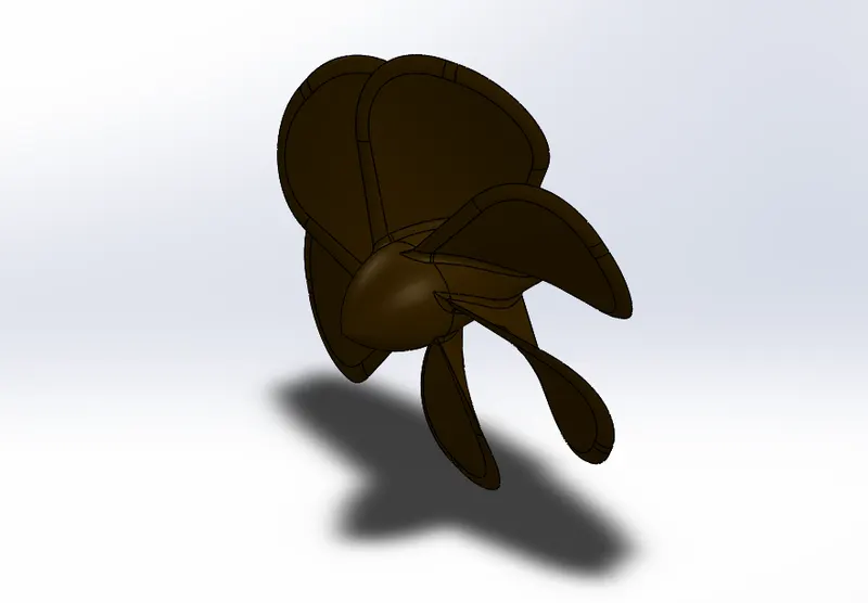
Features used to create Propeller
- Sketch
- Revolve
- Loft
- Fillet
- Cut Extrude
- Circular Pattern
- Appearances
Sketch
The Sketch is the basis for 3Dmodel. You can create sketch on any of the default planes such as Front, Top, Right plane or the created plane.
Revolve
Revolve add or remove materials by revolving one or more profiles around a centreline. You can create revolved boss/base, revolved cut, or a revolved surface. The revolve features can be solid, a thin feature or a surface.
Loft
Loft creates a feature by making transition between profiles by interpolating surfaces between various cross-section of the model. This cross-section can be sketches, faces, or edges. The corrections are considered as "Loft Profiles".
Fillet
Fillet/Round creates a rounded internal or external face on the part. You can fillet all the edges of a face, selected sets of faces, selected edges or edge loops.
Cut Extrude
The Extrude cut is another cool feature which helps to remove materials from the 3D model. It is just the opposite to extrude boss/ base feature, because it cuts a sketch profile while extruding. You can cut in both directions and mainly used for creating holes, channels, slots etc.
Circular Pattern
Circular Pattern is a type of pattern which is used create a feature of required instance in circular orientation.
Radar
Radar means Radio Detection and Ranging. It is used to detect objects and the position relates to the current location. Radar act as a major navigation aid for boaters. It helps in detecting boats, birds, landmasses and weather systems even if the visibility is less than uaual. The Radar is shown below,
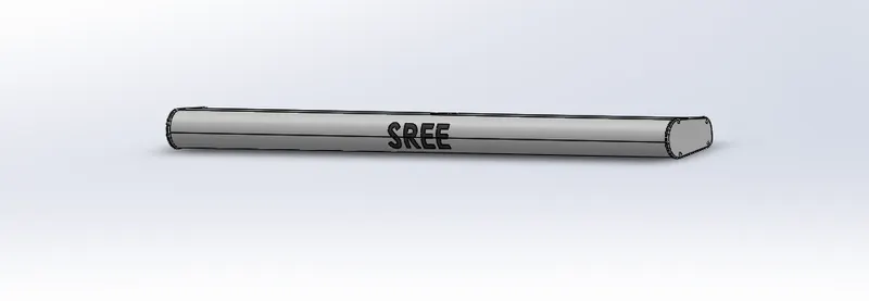
Features used to create Radar
- Sketch
- Boss Extrude
- Fillet
- Cut Extrude
- Sketch Pattern
- Mirror
- Split Line
- Sketch Text
- Appearances
Boss Extrude
Boss Extrude is a type of feature available in solidworks which is used to convert a 2D Sketch into 3Dmodels.
Sketch Pattern
The Curve Driven pattern tools allows to create patterns along a planar or a 3D curve. To define the pattern, you can use any sketch segment or edge of a face, that lies along the plane. It can make pattern on a open or a closed curve.
Split Line
The Solidworks Split Line tool is used to project an entity (sketch, solid surface, face, plane, or surface spline) onto another surface or curved/ planar faces on multiple bodies with one command.
Sketch Text
Sketch text on any set of continuous curves or edges (including circles or profiles made up of lines, arcs, or splines on the face of a part) and extrude or cut the text. The text is sketched along the outside edge of the face of the part, formatted, then cut. A sketched spline creates an offset edge.
Mirror
Mirror is used to mirror features, body with respect to a plane with option to merge solids or knit surfaces.
Blueprint
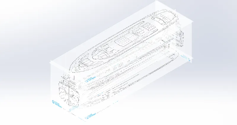
Generally, we set up the blueprint of any solid model for reverse engineering. It helps to roughly get an idea about the size and pattern of model. In this it is used to allocate the position of the Yacht. The height, length, and width of the blueprint is same as that of the yacht model.
- Front view Blueprint
- Bottom view Blueprint
- Top view Blueprint
- Side view Blueprint
- Back view Blueprint
The Blueprint model is shown below,
Hull
A hull is the watertight body of a ship, boat, or flying boat. The hull may open at the top (such as a dinghy), or it may be fully or partially covered with a deck. Atop the deck may be a deckhouse and other superstructures, such as a funnel, derrick, or mast. The hull of a ship is the most notable structural entity of the ship. To define the hull, it can be said that it is the watertight enclosure of the ship, which protects the cargo, machinery, and accommodation spaces of the ship from the weather, flooding, and structural damage. The Hull portion of the Yacht is shown below,
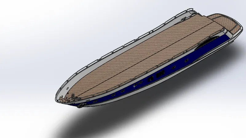
Features used to create Hull
- Sketch
- Projected Curves
- Linear Pattern
- Mirror
- Surface Extrude
- Surface Loft
- Extrude cut
- Fillet
- Chamfer
- Sweep
- Surface Knit
- Surface Trim
- Offset surface
- 3D Sketch
- Shell
- Helix/spiral
- Appearances
Projected Curve
Project a sketched curve onto a model face to create a 3Dcurve. You can also create a 3D curve that represents the intersection of two extruded surface generated by creating sketches on two intersecting planes. You can create multiple closed or open contour projected curve from a single sketch.
Linear Pattern
Linear Pattern is similar as the circular pattern. In this pattern the features or bodies are patterned in linear XYZ direction.
Surface Extrude
Using the SOLIDWORKS Surface Extrude feature, we can extrude the boundary edges of a face of a solid body or edges of a surface body in a customized direction.
Surface Loft
Loft Surfaces are surfaces generated by multiple 3D Curves or existing edges creating a smooth tangency between the selected curves. Match Points are created between each selection denoting the orientation and path of the loft surface.
Sweep
Sweep is the one feature that helps to sweep closed profile along a closed or open path.
Surface Knit
Surface knit is used to knit the two free edges/open edges of the surfaces together. Also, it reduces the gap between the two edges of the surface.
Surface Trim
Surface Trim is used to cut away the unwanted materials from one surface to another.
Surface Offset
The offset surface tool is useful way of creating a series of deposit or erosion contact surfaces from a reference mesh. The surface can be offset from the reference mesh by points or by a fixed distance, and additional options for offsetting to points can be adjusted once the surface has been created.
3D Sketch
A 3D sketch plane is a 2D plane that only exists inside the 3D sketch. When activated, sketching will happen exclusively on that plane and you will get behavior similar to when working in a 2D sketch.
Shell
The shell tool hollows out a part, leaves open the faces you select, and creates thin-walled features on the remaining faces. If you do not select any face on the model, you can shell a solid part, creating a closed, hollow model. You can also shell a model using multiple thicknesses.
Garage Door
A garage door is a large door on a garage that opens either manually or by an electric motor (a garage door opener). Garage doors are frequently large enough to accommodate automobiles and other vehicles. Small garage doors may be made in a single panel that tilts up and back across the garage ceiling. Less commonly, some garage doors slide or swing horizontally. Doors are made of wood, metal, or fiberglass, and may be insulated to prevent heat loss. The garage door of an yacht is shown below,
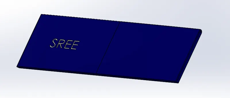
Features used to create Garage Door
- Sketch
- Extrude cut
- Mirror
- Fillet
- Shell
- Save Bodies
- Appearances
Save Bodies
It can also save solid bodies after you split the model using the Save Bodies feature. This enables you to save the bodies from a split part to a different folder or with different names to the same folder. You can also create an assembly from the split parts.
Appearances
Appearances defines the visual properties of a model, including colour and texture. Appearances do not affect the physical properties which are defined by the materials. Each material is assigned with a default appearance that emulates the look of the material.
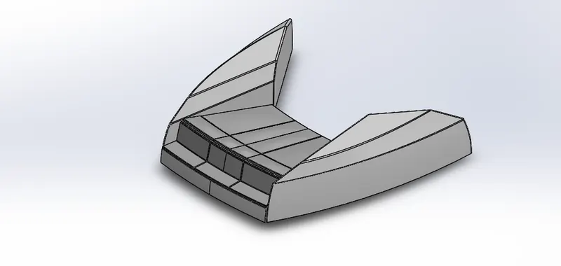
Front seat
Front seat is placed to hang out or to take rest on a yacht. It is placed in the front of the hull. It is used for the passenger comfort and their luxury. The front seat of the yacht is shown below,
Features used to create Front Seat
- Sketch
- Surface Sweep
- Surface Extrude
- Surface Knit
- Surface Fill
- Surface Trim
- Fillet
- Chamfer
- Revolve
- Dome
- Mirror
- Extrude cut
- Appearances
Surface Fill
The Filled Surface feature constructs a surface patch with any number of sides, within a boundary defined by existing model edges, sketches, or curves, including composite curves. You can use this feature to construct a surface to fill a gap in a model.
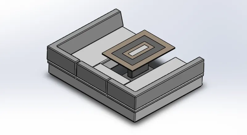
Middle Seat
Middle seat is placed to hang out or to take rest on a yacht. It is placed in the middle of the hull. It is used for the passenger comfort and their luxury. The middle seat of the yacht is shown below,
Features used to create Middle seat
- Sketch
- Surface Sweep
- Surface Extrude
- Surface Knit
- Surface Fill
- Surface Trim
- Fillet
- Chamfer
- Revolve
- Dome
- Mirror
- Extrude cut
- Appearances
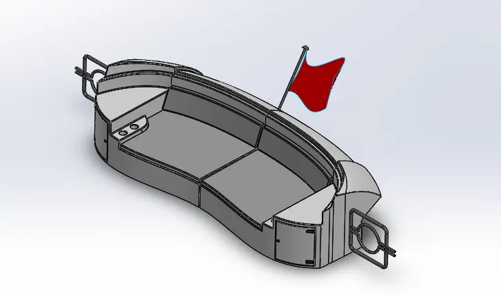
Rear seat
Rear seat is placed to hang out or to take rest on a yacht. It is placed in the rear part of the hull. It is used for the passenger comfort and their luxury. The rear seat of the yacht is shown below,
Features used to create Rear Seat
- Sketch
- Surface Sweep
- Surface Extrude
- Surface Knit
- Surface Fill
- Surface Trim
- Fillet
- Extrude Boss/Base
- Chamfer
- Revolve
- Dome
- Mirror
- Extrude cut
- Combine
- Appearances
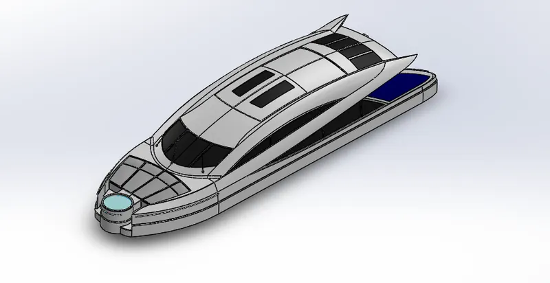
Superstructure
A Superstructure is an upward extension of an existing structure above a baseline. The term is applied to various kind of physical structures such as buildings, bridges, or a ship having the degree of freedom zero. The Superstructure of the yacht is shown below,
Features used to create Superstructure
- Sketch
- Surface Sweep
- Surface Extrude
- Surface Knit
- Surface Loft
- Surface Fill
- Ruled surface
- Surface Trim
- Delete Face
- Fillet
- Extrude Boss/Base
- Chamfer
- Revolve
- Dome
- Mirror
- Extrude cut
- Plane
- Combine
- Appearances
Dome
A Dome is a curved formation or structure. Faces to Dome. Select one or more planar faces. You can apply domes to faces whose centroid lies outside the face. This allows you to apply domes to irregular shaped contours.
Delete Face
The delete face command within solidworks becomes integral to the modelling process when you are dealing with imported geometry and surfaces. It’s great for removing geometry or enabling edits to existing geometry with no feature history.
Three Options for the Delete Face Command
- Delete: This option will remove the selected faces, leaving a void where the face or faces existed previously. If a face is deleted from a solid body, a surface body will be created. This is the quickest way to transform a solid body to a surface body.
- Delete & Patch: This option deletes a face from a body and automatically patches the void. The edges adjacent to the deleted face will be extended and then trimmed, leaving a distinct edge.
- Delete & Fill: This option deletes the selected faces and replaces them with a single unbroken face. The fill also has the option for tangent fill. With this option selected, the filled face will use tangent edges. With the option cleared the replacement face will use contact edges.
Radar Mast
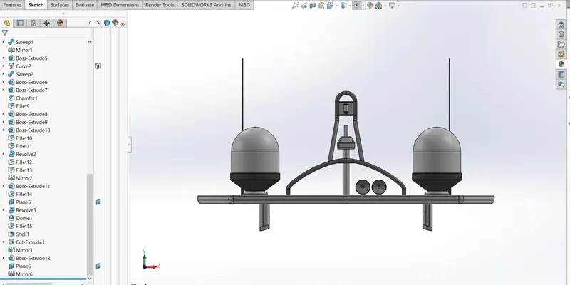
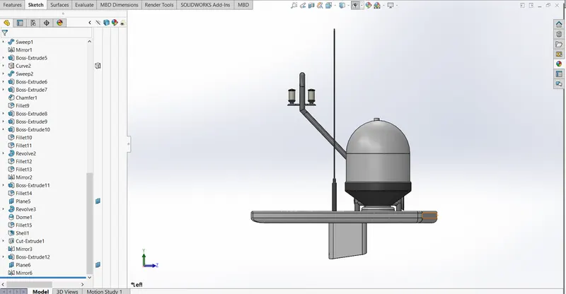
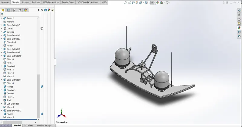
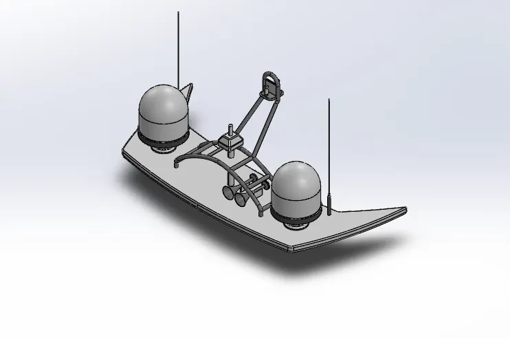
The Radar Mast or antenna is been installed in yacht. It helps and prevent the collision of vessels in fog and in low light. The radar is installed in the radar mast. The Radar mast of the yacht is shown below,
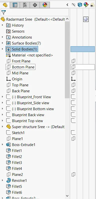
Features used to create Radar Mast
- Sketch
- Extrude Boss/Base
- Extrude Cut
- Revolve
- Sweep
- Fillet
- Shell
- Chamfer
- Curve
- Mirror
- Dome
- Appearances
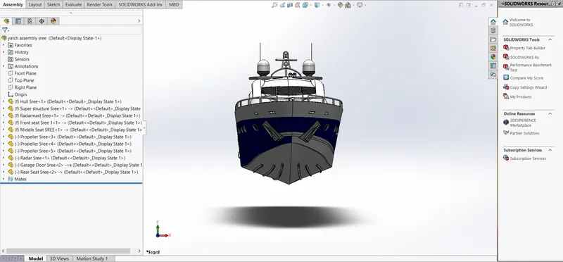
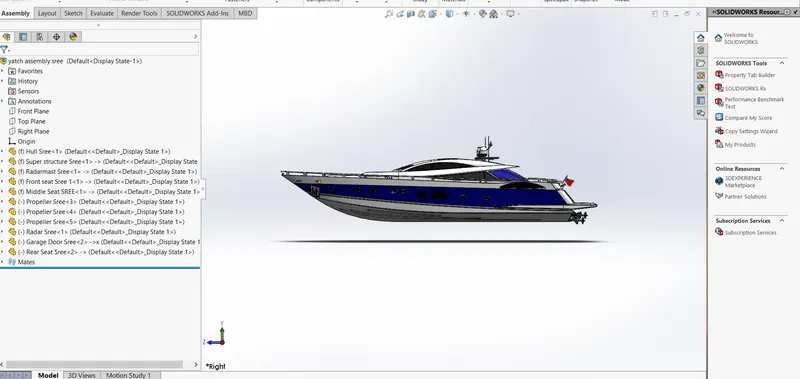
ASSEMBLY OF YACHT
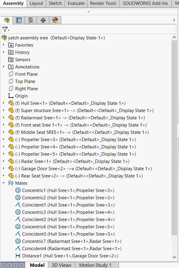
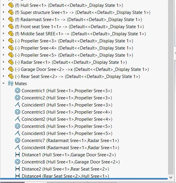
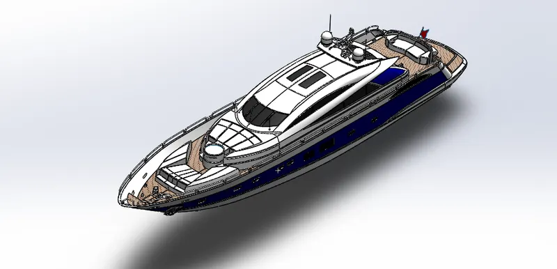
Assembly is the process of combining the different parts with sequence of joining through advanced mates like coincident, distance angle, concentric, parallel, width, limit angle etc..
Features used to create Assembly of Yacht
- Mates
- Insert part
Mates
Mates create geometric relationship between assembly components. As we add mates, we define the allowable directions of linear or rotational motion of the component. We can move a component within its degree of freedom, visualizing the assembly's behaviour.
PHOTOREALISTIC RENDERING OF CHOPPER
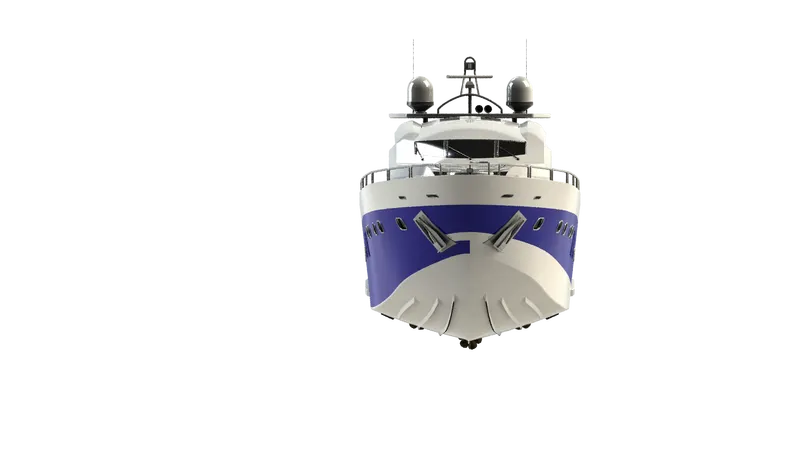
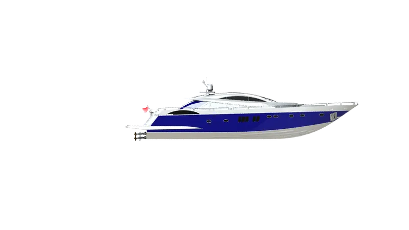
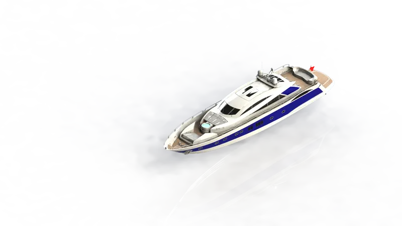
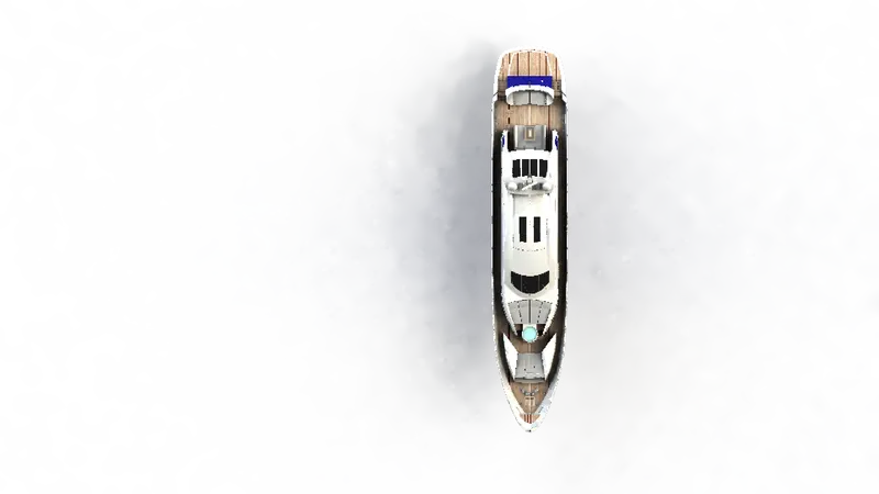
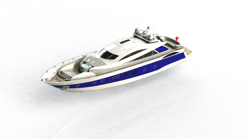
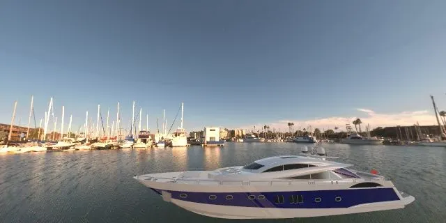
Rendering is the process of creating realistic image of the Photorealistic model with the environment. Rendering has been done in two ways in solidworks. They are
- Photoview360
- Solidworks Visualize
The rendering image of the Yacht are shown below
CONCLUSION
The parts of the Yacht are modelled, then modelled parts are inserted into the Assembly environment and the yacht is assembled by using the Solidwoks. The assembled yacht is rendered using Photoview 360 & Solidworks Visualize.
OUTCOME OF THE COURSE
Understanding the concept of Solidworks and implementing the concept in the project.