Photo Realistic Rendering
MODELLING OF AMERICAN CHOPPER ON SOLIDWORKS
OBJECTIVE
- The main objective of the project is to create a model of the parts and assemble the parts for Chopper by using Solidworks.
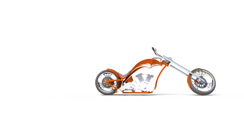
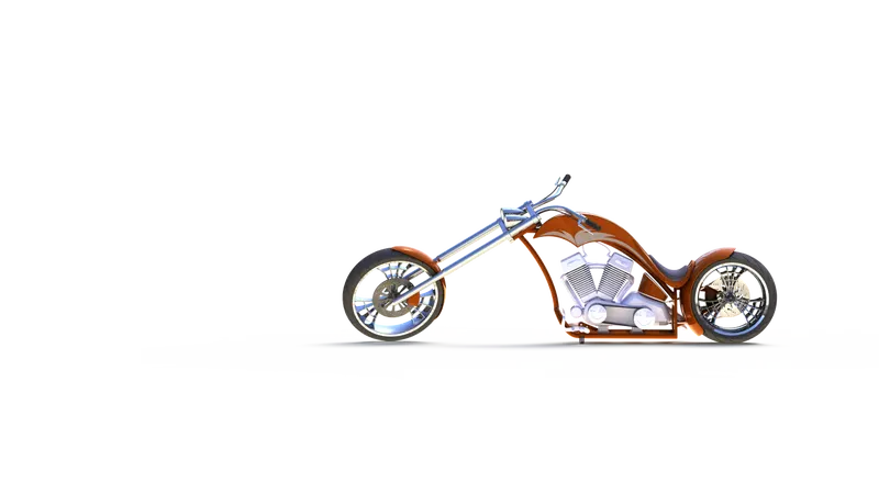
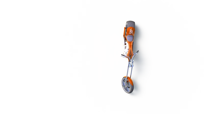
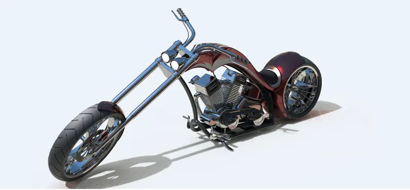
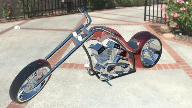
- To create a Photorealistic model of the Chopper and Render the chopper by using Solidworks Photoview360 and Solidworks Visualize.
PART MODELLING
Part Modelling is a process of creating a virtual prototype of something by modelling each individual parts separately, which can then assemble together to create a model of the final product. In this project the different parts of Chopper are modelled and then assembled together to form a Chopper. This type of modelling is called Part Modelling.
PARTS TO BE MODELLED FOR CHOPPER
The following parts of the Chopper are modelled in Solidworks and assembled
- Transmission Belt
- Kick stand
- Front Fender
- Rear Fender
- Oil Tank
- Chain
- Pedal
- Front Wheel
- Rear Wheel
- Front Fork
- Chassis
- Engine
- Gas Tank
1.Transmission Belt
The Transmission Belt in the Chopper is used to transmit the power from the Engine to the Gearbox. The Transmission Belt is shown below,
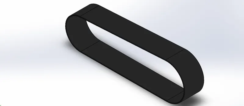
Features used to create Transmission Belt
- Sketch
- Offset
- Extrude
- Fillet
- Appearances
Sketch
Sketch is the 2D representation of the model with respect to the plane/view from the outside of the model. In solidworks there are different sketch options available to create a sketch. These are known as Entities in solidworks. The entities which available in solidworks are Line, Arc, Spline, Circle, Rectangle.
Offset
Offset one or more sketch entities, selected model edges or model faces by a specified distance. For example, you can offset sketch entities such as splines or arcs, sets of model edges, loops and so on. You can also offset finite lines, arcs, and splines.
Extrude
Extrude is a type of feature available in solidworks to convert a 2D sketch into 3D models.
Fillet
Fillet creates a rounded internal or external face on the part. You can fillet all the edges of a face, selected sets of faces, selected edges, or edge loops.
2.Kick stand
Kick stand is nothing but a component for supporting a bicycle or motorcycle when not in use. It is also known as side stand. The Kick stand is shown below,
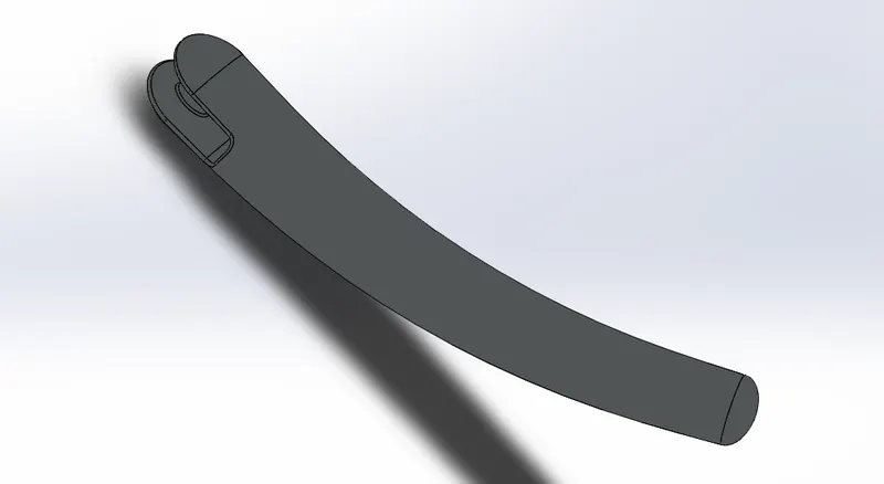
Features used to create Kick Stand
- Sketch
- Loft
- Dome
- Extrude Boss
- Extrude Cut
- Fillet
- Split
- Appearances
Loft
The Loft feature in solidworks allows you to generate complex geometry in a single feature. It does this by interpolating surfaces between various cross-sections of a model. These cross-sections can be sketches, faces, or edges. In the loft interface, these cross- sections are considered as "Loft Profiles".
Dome
A Dome is a curved formation or structure. Faces to Dome. Select one or more planar faces. You can apply domes to faces whose centroid lies outside the face. This allows you to apply domes to irregular shaped contours.
Extrude Cut
Extrude cut is another cool feature which helps to remove materials from the 3D model. It is just the opposite to extrude boss/ base feature, because it cuts a sketch profile while extruding. You can cut in both directions and mainly used for creating holes, channels, slots etc.
Split
The Solidworks Split Line tool is used to project an entity (sketch, solid surface, face, plane, or surface spline) onto another surface or curved/ planar faces on multiple bodies with one command.
3.Front Fender
Front fender is a part mounted on the fork above the wheel to protect the rider and the other parts of chopper from debris and the foreign particles. The front fender is shown
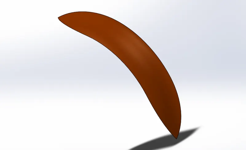
Features used to create Front Fender
- Sketch
- Offset
- Trim
- Revolve
- Dynamic Mirror
- Split
- Appearances
Trim
Trim tool is mainly used to removing the unwanted portions or parts in the design sketch. All trim is available with 2D sketches and 2D sketches on 3D planes. The trim tools are of different types which are Power trim, Corner trim. Power trim is used in the fender.
Revolve
Revolve feature is an axisymmetric shape that is created by revolving an open or closed section view by a specified angle around a central axis. The section can represent a protrusion or a cut, that is, it can either add material or take it away.
Dynamic Mirror
Dynamic mirror is the important tool in solidworks. As you sketch the entities, they are mirrored about the pre-selected sketch entities.
4.Rear Fender
Rear Fender is used same as the front fender. The rear fender is mounted on the chassis of the rear part above the rear wheel. It primary purpose is to prevent sand, muds, stones, liquid waste and other road spray from being thrown into the air by the rotating tyre. The Rear fender is shown below
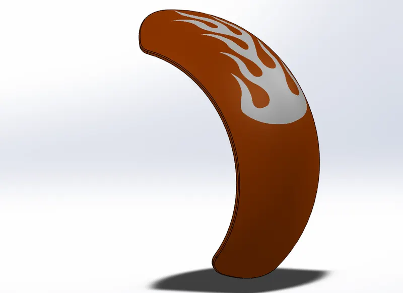
Features used in Rear Fender
- Sketch
- Offset
- Trim
- Revolve
- Appearances
Appearances
Appearances defines the visual properties of a model, including colour and texture. Appearances do not affect the physical properties which are defined by the materials. Each material is assigned with a default appearances that emulates the look of the material.
5.Oil Tank
Oil tank is used to store the oil which is required to run the Engine. It is also used to lubricate parts. The oil tank is shown below,
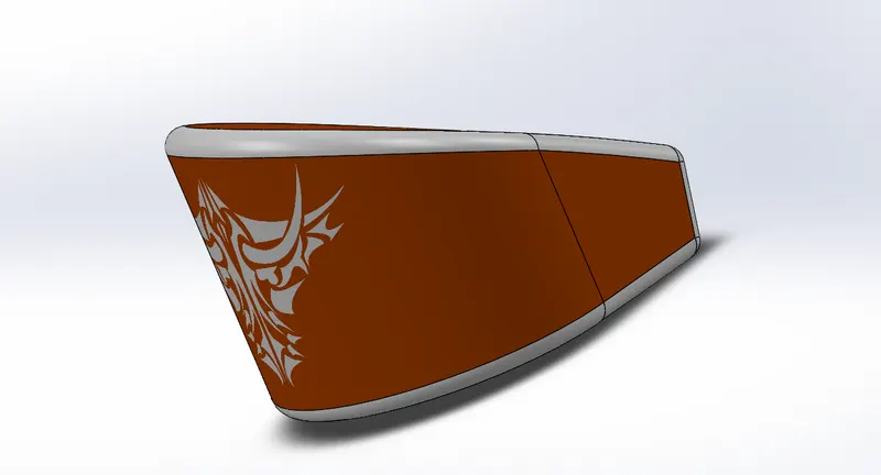
Features used to create Oil Tank
- Sketch
- Boss Extrude
- Combine
- Fillet
- Shell
- Appearances
Combine
Combine is a type of feature available in solidworks. It is used to merge two or more bodies into a single solid part.
Shell
Shell feature hollows out the inside of solid, leaving a shell of a specified wall thickness. It specifies a surface or surfaces that want to remove from the shell.
6.Chain
Chain is a type of transmission system that is used to transmit a power from the Engine to the Rear wheel. The sprocket is used to transmit the power to the chain. The sprocket is connected with the Shaft with the help of a key. The chain is shown below,
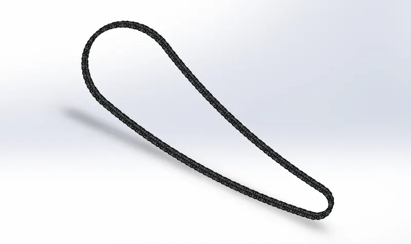
Features used to create Chain
- Sketch
- Trim
- Fillet
- Blocks
- Extrude
- Patterns
- Appearances
Blocks
In Block feature you can make, save, edit and insert blocks for the drawing items and sketch entities that you use often, such as standard notes, title blocks, label positions and so on. It can attach to the geometry or the drawing views, and can insert them into sheet formats.
Patterns
The pattern command is used for the replication and improving the overall efficiency. There is different type of patterns are present in the solid works such as Linear patter, Curve driven pattern etc. In this curve driven pattern is used . It is used to create pattern along the planar or 3D Curve.
7.Pedal
The pedal is the external part attached to the Chassis. It is used to give comfort to the rider and maintain balance to the feet. The pedal is shown below
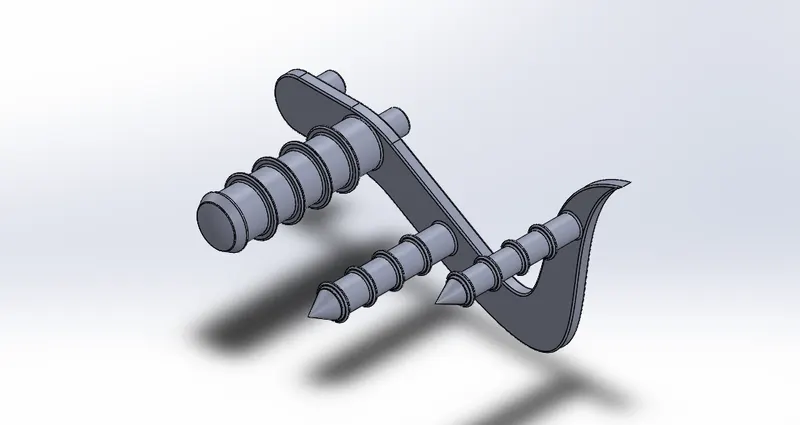
Features used to create Pedal
- Sketch
- Extrude
- Fillet
- Linear Pattern
- Dome
- Chamfer
- Appearances
Chamfer
Chamfer is to creates angled cut to make the corner flat. It also has many options such as Angle-Distance, Distance-Distance, Vertex, Offset face and Face-face.
Linear Pattern
Linear Pattern is similar as the circular pattern. In this pattern the features or bodies are patterned in linear XYZ direction.
8.Front Wheel
A wheel is a circular block of a hard and durable material at which centre has been bored a circular hole through which a front axle bearing is placed. It rotates the wheel when moment is applied by gravity or torque to the wheel. The Front wheel is shown below
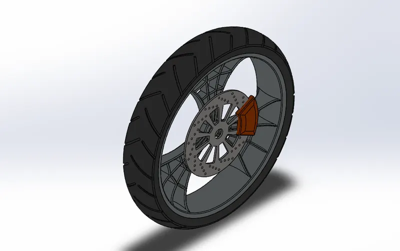
Features used to create Front wheel
- Sketch
- Revolve
- Trim
- Fillet
- Boss/Base Extrude
- Revolve Cut
- Linear Pattern
- Chamfer
- Cut Extrude
- Circular Pattern
- Appearances
Circular Pattern
Circular Pattern is used to create solid surface in the circular direction. It is used to create rim, spokes, holes and vents on the disc plate, Tyre tread etc...
9.Rear Wheel
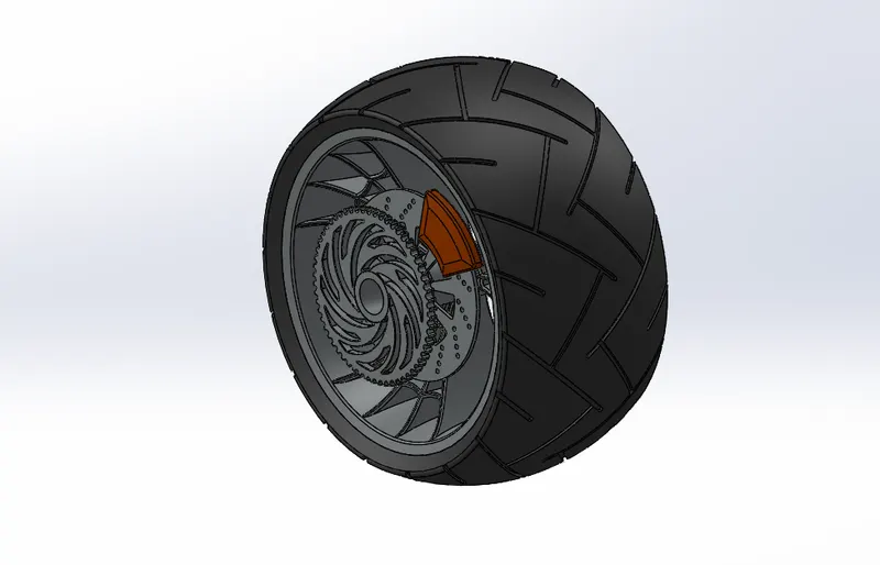
A wheel is a circular block whose centre is bored a circular hole through which the rear axle bearing is placed. It is mounted to the rear of the chassis. It has sprocket and disc plate in it. The Rear wheel is shown below
Features used to create Rear Wheel
- Sketch
- Trim
- Revolve
- Fillet
- Boss/Base Extrude
- Planes
- Revolve cut
- Linear Pattern
- Chamfer
- Cut Extrude
- Circular Pattern
- Appearances
Revolve Cut
Revolve cut is command is used to cut a solid geometry by revolving about an axis.
10. Front Fork
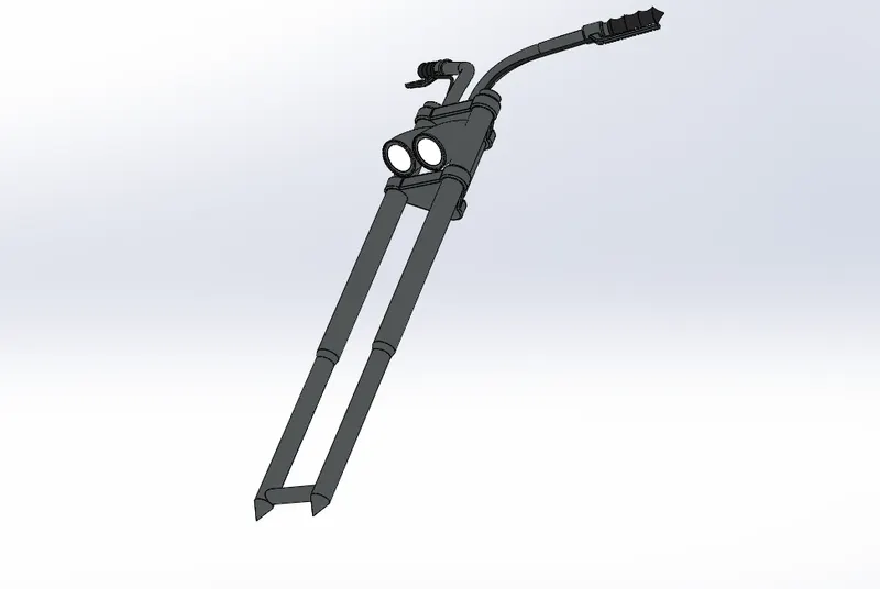
The fork is large hydraulic shock absorbers with internal coil springs. This allow the front wheel to react to imperfections in road while isolating the rest of motorcycle from the motion. The front Fork is shown below
Features used to create Front Fork
- Sketch
- Extrude
- Trim
- Revolve
- Split
- Plane
- Convert Entities
- Move/Copy Body
- Dome
- Mirror
- Combine
- Curve
- Sweep
- Appearances
Move/Copy Body
Move/Copy body is used to move /copy the body from one place to another place in fork.
Mirror
Mirror is used to mirror features, body with respect to a plane with option to merge solids or knit surfaces.
Project Curve
The project curve is the kind of 3D curve that is projected on the basis of the two different 2D Sketch.
Sweep
The sweep feature is used to create a shape by moving a 2D sketch profile along a 2D or 3D Sketch path.
11.Chassis
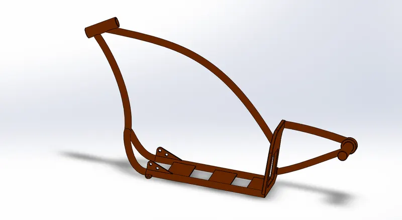
A Chassis or frame forms it skeleton. It is the part where the other parts of the chopper are assembled to it. It gives overall shape to the chopper. The chassis is shown below
Features used to create Chassis
- Sketch
- Sketch Picture
- Offset
- Convert Entities
- Project curve
- Trim
- Plane
- Sweep
- Split
- Revolve
- Cut Extrude
- Fillet
- Combine
- Appearances
Sketch Picture
Sketch Picture is used to insert an image or blueprint of the model into a work plane, from which we can draw the required sketch.
12.Engine
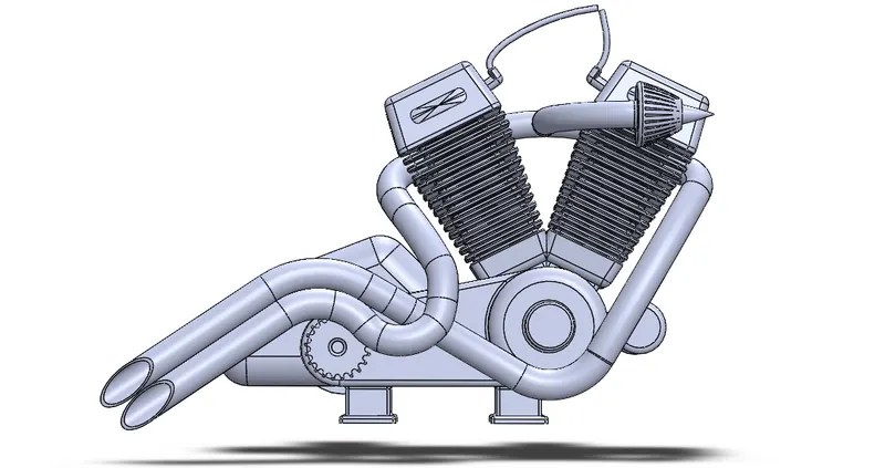
Engine is the prime mover for the Bike. The Engine converts chemical energy into Heat Energy and then the hear energy is converted into mechanical work. The power from the Engine is transmitted to real wheel through sprocket and chain assembly. The Engine sketch is shown below
Features used to create Engine
- Sketch
- Convert Entities
- Trim
- Revolve
- Boss Extrude
- Cut Extrude
- Offset
- Dome
- Project Curve
- Fillet
- Composite Curve
- Sweep
- Mirror
- Circular Pattern
- Split
Composite Curve
It is used to create single curve by combining curves, sketch geometry, and model edges. Composite curve can be used as a guide curve when creating a loft or a sweep.
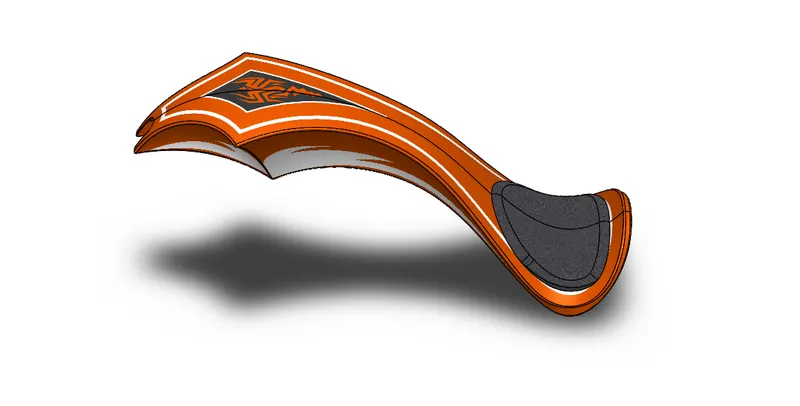
13.Gas Tank
Gas Tank is used to store the gas. It gives the gas to the engine when it's required. It is mounted at top of the chassis frame. The gas tank is shown below
Features used to create Gas Tank
- Sketch
- Trim
- Project Curve
- Convert Entities
- Sweep Surface
- Loft Surface
- Fill surface
- Surface Trim
- Surface Knit
- Sweep Cut
- Fillet
- Appearances
Loft Surface
Loft Surface are surface generated by multiple 3D curves or existing edges creating a smooth tangency between the selected curves.
Sweep Surface
Sweep Surface are surface that is generated from a section curve positioned along a path.
Surface Trim
Surface Trim is used to cut away the unwanted materials from one surface to another.
Surface Knit
Surface knit is used to knit the two free edges/open edges of the surfaces together. Also, it reduces the gap between the two edges of the surface.
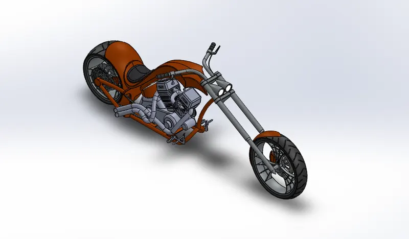
ASSEMBLY OF CHOPPER
The Chopper Assembly is done in the assembly environment all the parts which are modelled before being inserted into the assembly environment by using insert component feature. The Components are fixed in the assembly environment based on some reference such as planes, mates etc..
Features used to create Assemble Chopper
- Mates
- Insert Part
Mates
Mates create geometric relationship between assembly components. As we add mates, we define the allowable directions of linear or rotational motion of the component. We can move a component within its degree of freedom, visualizing the assembly's behaviour.
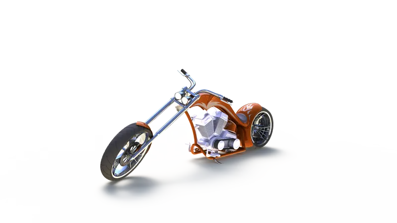
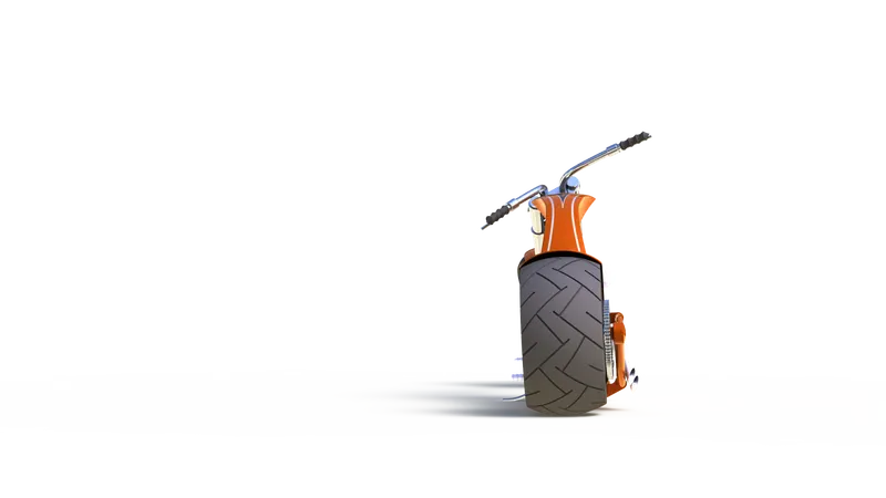
PHOTOREALISTIC RENDERING OF CHOPPER
Rendering is the process of creating realistic image of the Photorealistic model with the environment. Rendering has been done in two ways in solidworks. They are
- Photoview360
- Solidworks Visualize
The rendering image of the Chopper are shown below
CONCLUSION
The parts of the chopper are modelled, then modelled parts are inserted into the Assembly environment and the chopper is assembled by using the Solidwoks. The assembled chopper is rendered using Photoview 360 & Solidworks Visualize.
OUTCOME OF THE COURSE
Understanding the concept of Solidworks and implementing the concept in the project.