ASSEMBLY AND PHOTO REALISTIC RENDER OF YACHT
ASSEMBLY AND PHOTO REALISTIC RENDER OF YACHT
- Objective:
To design and model various parts of Yacht and assemble in SOLIDWORKS and photo realistic render by using SOLIDWORKS visualize.
- Introduction:
A design is a plan for developing a product. Today every product is designed by the need of customers and computer-aided design (CAD) is the use of computers to aid in the creation, modification, analysis, or optimization of a design. CAD software is used to increase the productivity of the designer, improve the quality of design, improve communications through documentation.
SolidWorks is a solid modelling computer-aided design (CAD) and computer-aided engineering (CAE) computer program published by Dassault Systèmes.
In this software we can design a part model by help of tools and features and assemble all the part model by assembly feature. There are two types of modelling surface and solid.
- Design methodology:
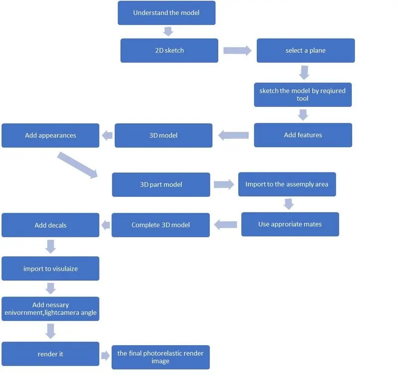
In this project we chosen bottom-up design method. The parts of Yacht are sketched with proper dimensions and relations and then 3D modelled by appropriate features like extrude boss, fillets etc. then the parts are being assembled to final complete model of Yacht with appropriate mates. Then decals and scene setup are added to get the perfect environment. The final part render is done in SOLIDWORKS visualize to get photorealistic image.

Design process flow chart
PART MODELLING
Part modelling is a process where we create individual parts by 2D sketching in respective plane suitable tools like line tool, circle,3 point arc etc and then converting them to 3D part by suitable features like extrude boss, revolve boss, sweep boss etc.
TOOLS
- Line tool: This tool is used to draw line and arcs.
- Circle: This tool is used to draw circle.
- 3-point arc: This tool is used to draw arc with center point as reference.
- Ellipse: This tool is used to draw ellipse.
- Spline: This tool is used to draw complex curve.
- Rectangle: This tool is used to draw rectangle.
- Dynamic mirror: This tool is used mirror the sketch about a reference line
- Offset entities: This tool is used create offset of sketch.
- Extend entities: This tool is used extended entities to meet another sketch.
- Trim entities: This tool is used trim or remove the unwanted sketch.
- Convert entities: This tool is used make a copied projection of a sketch.
- Block: This tool is used to create a sketch and make the sketch entities as sketch tool.
- Sketch filet: This tool is used to add filet in the sketch.
- Smart dimensions: This tool is used to add or modify dimensions.
FEATURES
- Extrude boss/base: This feature is used to convert 2D sketch to 3D model by adding thickness.
- Revolve boss/base: This feature is used to convert 2D sketch to 3D model by revolving a profile around an axis.
- Sweep boss/base: This feature is used to create a solid by moving a profile along a path.
- Fillet: This feature is used to create smooth round surface in the edge of the model
- Split: This feature is used to project an entity onto another surface.
- Dome: This feature is used to create dome
- Extrude cut: This feature is used to remove the part material from as solid material along a axis.
- Linear pattern: This feature is used to create patterns of solid model in a linear path
- Combine: This feature is used to add two or more bodies together.
- Shell: This feature is used to make solid body into hallow body.
- Chamfer: This feature is used to create beveled on the selected face or edge.
- Mirror: This feature is used to mirror a feature about a plane.
- Delete face: delete face from solid bodies to create surface entit
- Movecpoy body: This feature is used to move or copy a body to one place to another pace.
- Swept surface: This surface feature is used to create a surface using section curves positioned alone a path.
- Extrude surface: This surface feature is used to create an extruded surface.
- Filled surface: This surface feature is used to create a surface patch within the boundary.
- Boundary surface: This surface feature is used to create surface that can be tangent or curvature continuous in both directions.
- Lofted surface: This surface feature is used to create a lofted surface.
- Knit surface: This surface feature is used to combine one or more surface in to one surface.
- Swept cut: This surface feature is used to remove material of a body along a sweep path.
- Trim surface: it is used to remove the excess surface.
PART MODELLING
- Propeller
- Radar
- Hull
- Garage door
- Front seat
- Middle seat
- Rear seat
- Superstructure
- Radar mast
PROPELLER
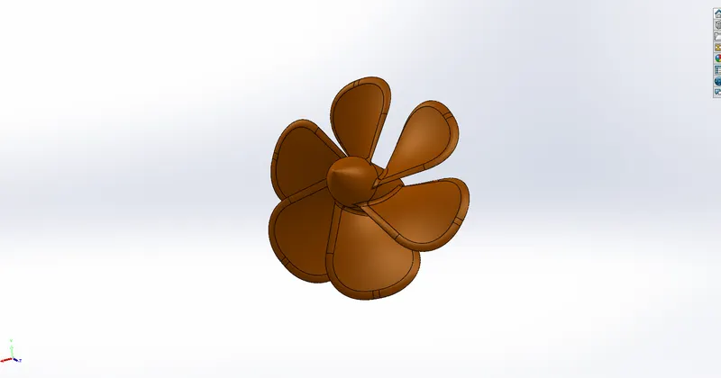
The purpose of the propeller is to provide a method of propulsion, so the yacht is able to move forward through the air. The propeller itself consists of two or more blades connected by a central hub that attaches the blades to the engine shaft.
Features used
- Revolved boss/base
- Lofted surface
- Circular driven pattern
Procedure
- Select the required plane for sketch.
- For propeller hub and cap Sketch a structure using line and spline and revolve it.
- For blade create a new plane offset from top plane and sketch a rectangle and sketch a rectangle in top plane by using these two sketches use loft for creating a solid structure.
- Add fillet.
- Use circular pattern for replicating the blades
- Sketch a circle at bottom and extrude
- Add fillet.
- Change appearance.
RADAR
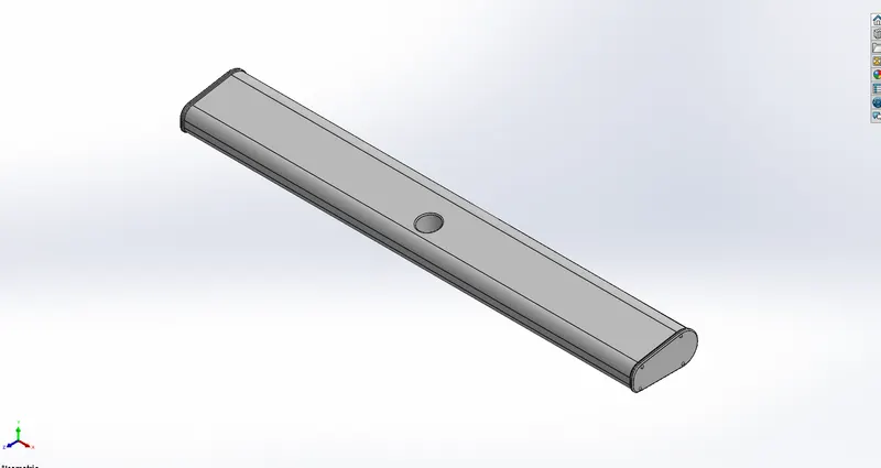
Radar (Radio Detection and Ranging) is a detection system that uses radio waves to determine the distance (range), angle, or velocity of objects. It can be used to detect aircraft, ships, spacecraft, guided missiles, motor vehicles, weather formations, and terrain.
Features used
- Extruded boss/base
- Extrude cut
- Fillet
- Sketch driven pattern
- Mirror
- Convert entities
- Split line
Procedure
- Select the required plane for sketch.
- Sketch a trapezium by using line tool and extrude.
- For bolts select the face and sketch it and extrude.
- Sketch a circle on the face and do perform extrude cut.
- Use sketch pattern to replicate the bolts.
- Now mirror across right plane.
- Draw a circle in the bottom and perform extrude cut.
- Change the appearance.
HULL
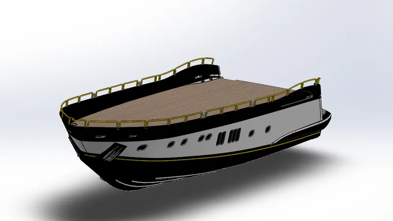
The hull of a ship is the most notable structural entity of the ship. To define the hull, it can be said that it is the watertight enclosure of the ship, which protects the cargo, machinery, and accommodation spaces of the ship from the weather, flooding, and structural damage.
Features used
- Extrude surface
- Extended surface
- Filled surface
- Trim surface
- Knit surface
- Filled surface
- Sweep boss/base
- Offset entities
- Convert entities
- Project curve
- Shell
- Delete face
- Trim entities
Procedure
- Open the blueprint setup
- Draw two sketch using lines and splines in midplane and bottom plane and use projected curve by using the two sketches.
- Similarly create one more projected curve on mid and back plane.
- Now create a surface loft by two projected curves.
- Similarly create one more surface loft by drawing sketches by using spline on mid and back plane.
- Trim the extra surface by sketching a line.
- Draw a spline parallel to surface loft and do surface loft.
- Draw a horizontal line and vertical line to surface extrude.
- Trim the extra surfaces.
- Use knit tool to knit them together.
- Fill the patchy area by using filled surface.
- Again, use knit tool.
- Offset created surface entities inwards and sketch using line to make the closed surface
- Trim the extra surface.
- Sketch using splines and do cut extrude.
- Apply fillet and chamfer.
- For side windows draw a rectangle add sketch fillet and do linear pattern and remove the extra windows.
- For port holes draw sketch a straight slot copies 1 the slot to another port holes using copy feature and use cut extrude use sweep tool for border as circle as profile.
- For lower deck create a sketch with help of blueprint and do extrude.
- For staircase create sketch by rectangle in top plane and use cut extrude and select the right face and sketch stairs using horizontal and vertical line and extrude up to next.
- For lower hull offset the bottom plane draw sketch with help of blueprint and extrude them.
- For anchor house draw a sketch on hull’s top face using circle and connect them by lines and trim the inner circles and draw a vertical and horizontal line on a new plane using the previous sketch as a reference and revolve it. create a sketch by drawing lines and circle extrude it. and use cut extrude to remove some portion.
- For rope create a helix and create plane by helix as reference draw at the endpoint of the helix as path and circle as profile create a sweep.
- And create extra portholes at the front end and rear end,
- For calliper sketch by using lines on the back plane and extrude it. Draw a sketch with the help of a blueprint and revolve it.
- For propeller on the back of the hull draw a sketch with the help of a blueprint and extrude it.
- For connecting rod use 3d sketch line to connect both propeller and extrude.
- For anchor sketch on the midplane using lines and splines with the help of a blueprint and extrude it.
- For garage door sketch a rectangle on midplane and do cut extrude convert the previous sketch as entities and extrude it. Now use split tool and remove the appropriate portion and save it
- Create a pin for garage door.
- Create a ketch by splines in midplane and offset it upward and downward direction and use split lines and select all face to split.
- Change the appearance
- Mirror all the bodies.
GARAGE DOOR
A garage door is a large door on a garage that opens either manually or by an electric motor (a garage door opener). Garage doors are frequently large enough to accommodate automobiles and other vehicles.
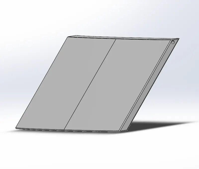
Features used
- Extrude boss/base
- Extrude cut
- Fillet
Procedure
- Open garage door part which saved while designing hull.
- Create a sketch on the face by lines and perform extrude cut.
- Apply shell by selecting the deck.
- Sketch a circle on side top region and cut extrude it.
- Change the appear
FRONT SEAT
The front seat is used for seating and to enjoy the view it is located at front side of hull.
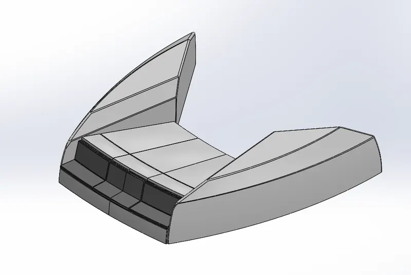
Features used
- Swept surface
- Dome
- Lofted surface
Procedure
- Open the blueprint setup
- Insert the hull part by the selecting the surface body
- Sketch on deck of the surface by using splines and create swept surface.
- Trim the extra surface.
- Fill the extra surface.
- Create surface loft using above sketches.
- Trim the extra surface.
- Knit the surface together.
- Draw lines to create the seat and revolve.
- Add fillet and dome.
- Change the appearance.
MIDDLE SEAT
The middle seat is used for seating and chill out it is located at middle side of hull.
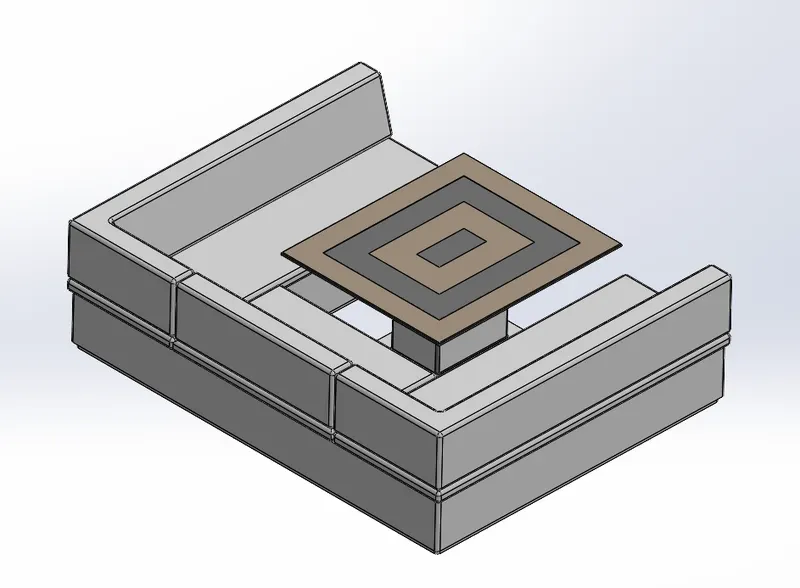
Features used
- Extrude boss/base
- Extrude cut
- Fillet
Procedure
- Open the blueprint setup
- Insert the hull part by the selecting the surface body
- Draw L shape using lines and extrude it.
- Create a sketch on the above extrude face offset the face and extrude.
- Create a plane above extrude. Sketch on it by the help of the blueprint.
- Mirror the bodies.
- Create table on sketching in deck surface.
- Create a cut extrude on top surface.
- Add fillets.
- Change appearance.
BACK SEAT
The back seat is used for seating and to enjoy the view it is located at rear side of hull.
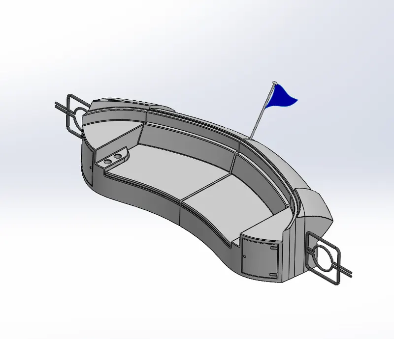
Features used
- Offset surface
- Ruled surface
- Extrude cut
- Fillet
SUPER STRUCTURE
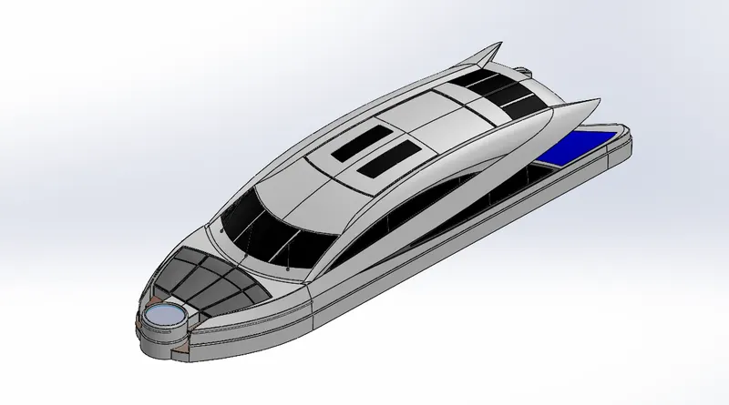
A superstructure is an extended construction of any building or platform that rises above the rest of the building or platform in a distinct manner. superstructure means to add a construction to an already existing structure. In ships this is the name given to the part of the ship that emerges from the deck.
Features used
- Swept boss/base
- Projected curve
- Shell
- Trim entities
- Offset entities
- Convert entities
- Extend surface
- Filled surface
- Delete faces
- Extruded surface
- Trim surface
- Knit surface
Procedure
- Open the blueprint setup.
- Insert the hull part by the selecting the surface body.
- Create a sketch by splines and lines with help of blueprint on deck surface and extrude it.
- Create a plane at the end of surface extrude.
- Create surface sweep by creating sketch on the plane on the created plane using lines and apply pierce relation with the extrude surface.
- Extended the outer edge of the surface of the edge using ruled surface at an angle.
- Trim the extra surface.
- Knit all the surfaces.
- Create a lofted surface by two projected curves.
- Create surface sweep by creating sketch using lines and apply pierce relation with the extrude surface.
- Trim the extra surface.
- Create surface sweep by creating sketch on mid plane using lines and apply pierce relation with the extrude surface.
- Trim the extra surface.
- Using blueprint draw two sketches by using lines and splines and project them and use lofted surface.
- For side windows select the outer surface of superstructure and use ruled surface.
- Trim the extra surface.
- Sketch by using lines and use surface extrude it in deck face.
- Trim the extra surface.
- Knit all the surfaces.
- Draw a sketch.
- For steps draw horizontal and vertical lines and extrude them.
- Trim the extra surface.
- For mattress create a surface offset at the front end and trim the extra surface and thicken surface by selecting respective faces. create a cut extrude and apply domes and fillet.
- For railing create a sweep by drawing sketches on respective planes using circles and spline.
- For door create a cut extrude by offsetting the rear face inwards.
- For front glass create a sketch on top planes by offsetting entities and do cut extrude.
- For frames sketch two lines and converting the top and bottom edges of the glass. Trim unwanted entities and perform extrude.
- Do similarly for top, side, and rear frame and top glass.
- For wipers holders create a sketch by circle and extrude them in top face of superstructure.
- Crate an offset surface in top of the superstructure for reference for radar mast
- For wiper create a rectangle on a respective plane and boss extrude and apply chamfer and use cut extrude draw a 3d line from wiper-to-wiper holder and extrude it do it for other side.
- Change the appearance
RADAR MAST
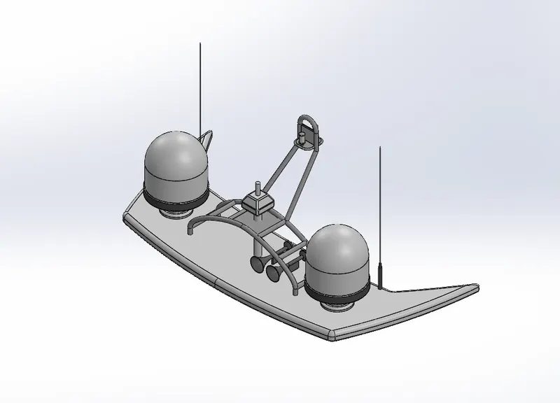
It does so by detecting other ships and land obstacles, to give bearing and distance for collision avoidance and navigation while on water. A marine radar device acts as a major navigation aid for boaters. It helps in detecting boats, birds, landmasses, and weather systems.
Features used
- Extrude boss/base
- Extrude cut
- Fillet
- Swept boss/base
- Mirror
Procedure
- Open the blueprint setup.
- Insert the super structure part by the selecting the surface body.
- Create a sketch on the surface of the radar surface and extrude and add fillets.
- Create a plane by sketching splines as references.
- For radar indicator sketch a structure by using line and 3-point arc and revolve it. Sketch a circle on the extrude face and extrude it apply fillet.
- For antenna sketch a circle and extrude and again do the same procedure twice and add fillet.
- Create a sweep by drawing a circle and spline on 3d sketch.
- Mirror above sweeps across plane 2 and connects them by drawing 3 circle and extrude them.
- Create a projected curve by two curve and create sweep by drawing circle.
- For horn draw a few lines and spline as per blueprint, revolve it, and apply dome to one end and shell to other.
- Mirror all feature except horn/.
- Draw a rectangle and extrude it to the surface of the horn.
- Mirror the horn by creating a plane.
- Change the appearance.
ASSEMBLY OF YACHT
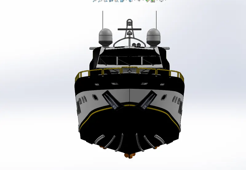
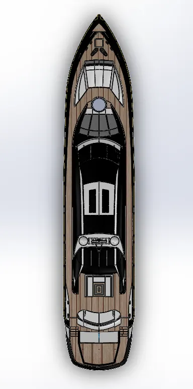
The assembly is a feature of SOLIDWORKS which is used to assemble all part models by suitable assembly mates.
There three types of assembly mates
- Standard mates: geometric relations such as perpendicular, parallel, concentric etc.
- Advance mate: in this option we can enter width, angle, linear etc values between the part models components.
- Mechanical mate: this option is used to stimulate the real time interaction such as movements by using Cam, gear, and universal joint.
FRONT VIEW
TOP VIEW
SIDE VIEW
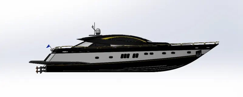
ISOMETRIC VIEW
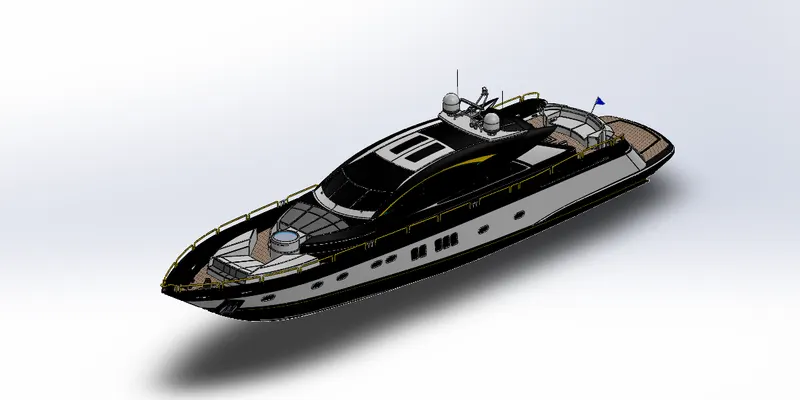
CAMERA VIEW
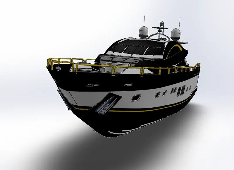
PROCEDURE
- Open SOLIDWORKS and select assembly option.
- First import hull part file into assembly area and fix it.
- Import all the other model by one by one and mate them by using suitable mates such us coincident, distance, limit angle and tangent etc
- Add suitable appearance and decals
- Then set the assembly model in required camera view.
RENDER IMAGE
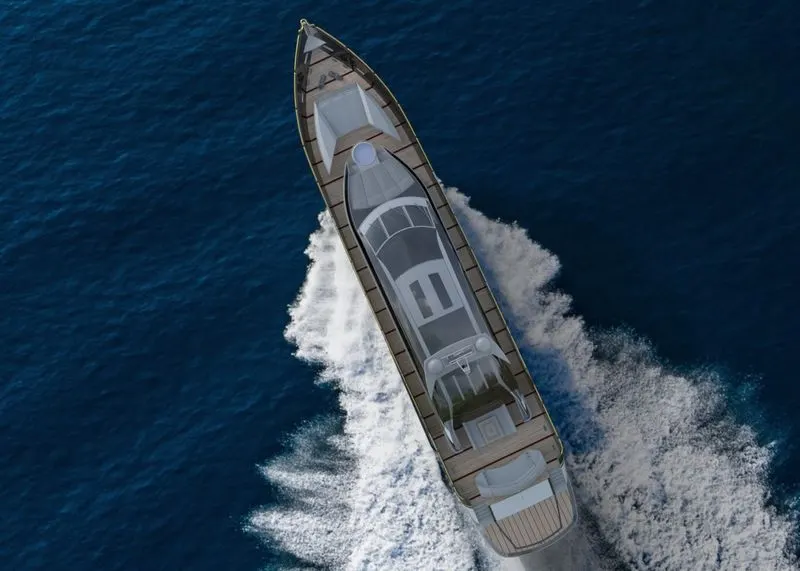
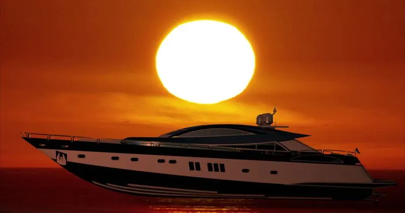
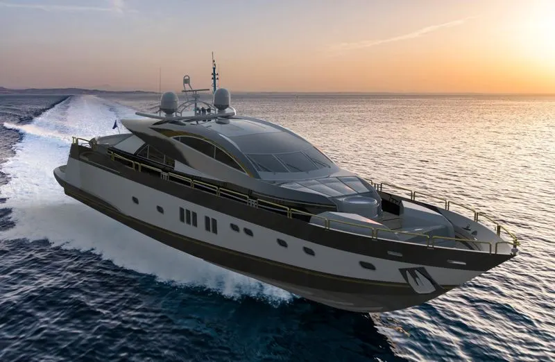
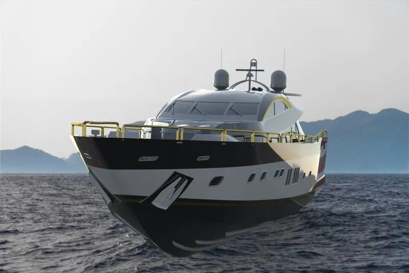
It is a process of creating realistic imaged of the model in the required environment. Rendering is done in photoview 360 and SOLIDWORKS visualize.
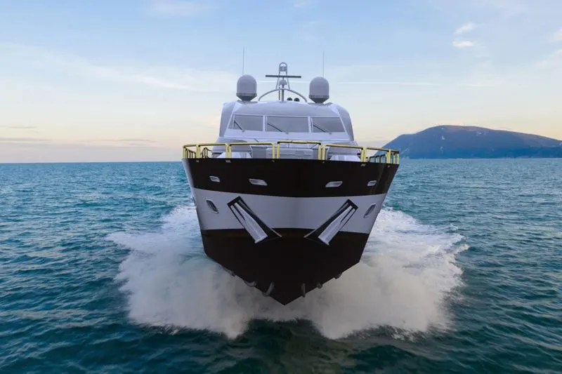
CONCLUSION
In this project I developed my surface and solid modelling skills and gained knowledge on the same.