ASSEMBLY AND PHOTO REALISTIC RENDER OF AMERICAN CHOPPER
ASSEMBLY AND PHOTO REALISTIC RENDER OF AMERICAN CHOPPER
- Objective:
To design and model various parts of American chopper and assemble in SOLIDWORKS and photo realistic render by using SOLIDWORKS visualize.
- Introduction:
A design is a plan for developing a product. Today every product is designed by the need of customers and computer-aided design (CAD) is the use of computers to aid in the creation, modification, analysis, or optimization of a design. CAD software is used to increase the productivity of the designer, improve the quality of design, improve communications through documentation.
SolidWorks is a solid modelling computer-aided design (CAD) and computer-aided engineering (CAE) computer program published by Dassault Systèmes.
In this software we can design a part model by help of tools and features and assemble all the part model by assembly feature. There are two types of modelling surface and solid.
- Design methodology:
Top-down In top-down assembly design, one or more features of a part are defined by something in an assembly, such as a layout sketch or the geometry of another part.
Bottom-down In bottom down assembly design process where each part is deigned separately and assembled by appropriate mates.
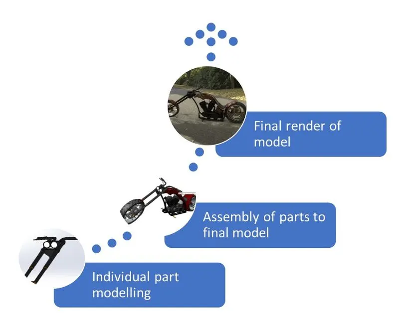
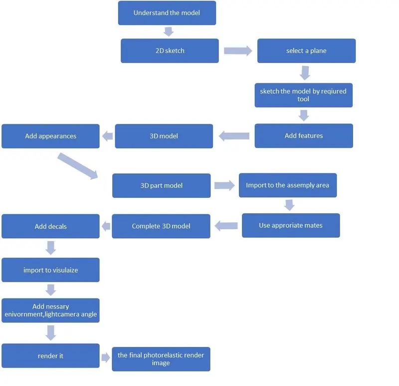
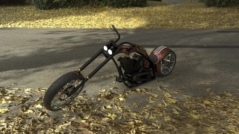
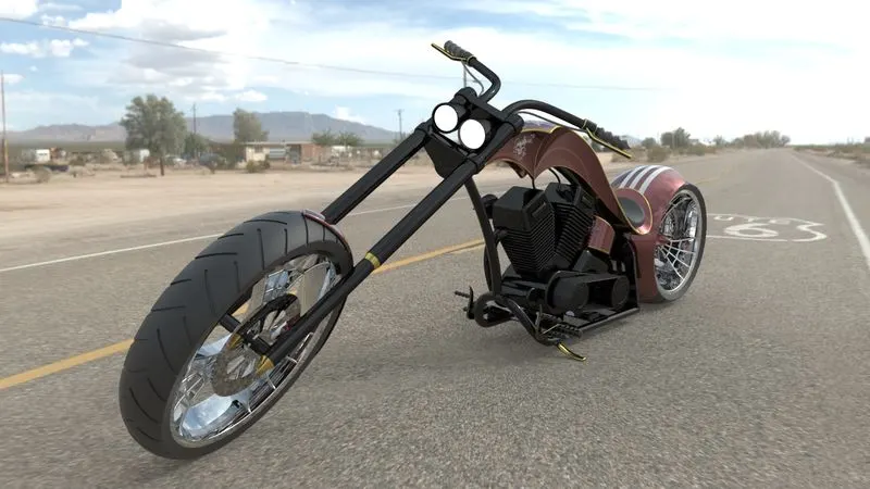
In this project we chosen bottom-up design method and solid modelling. The parts of American chopper are sketched with proper dimensions and relations and then 3D modelled by appropriate features like extrude boss, fillets etc. then the parts are being assembled to final complete model of American chopper with appropriate mates. Then decals and scene setup are added to get the perfect environment. The final part render is done in SOLIDWORKS visualize to get photorealistic image.
BOTTOM DOWN PROCESS
DESIGN PROCESS FLOWCHART
PART MODELLING
Part modelling is a process where we create individual parts by 2D sketching in respective plane suitable tools like line tool, circle,3 point arc etc and then converting them to 3D part by suitable features like extrude boss, revolve boss, sweep boss etc.
TOOLS
- Line tool: This tool is used to draw line and arcs.
- Circle: This tool is used to draw circle.
- 3-point arc: This tool is used to draw arc with center point as reference.
- Ellipse: This tool is used to draw ellipse.
- Spline: This tool is used to draw complex curve.
- Rectangle: This tool is used to draw rectangle.
- Dynamic mirror: This tool is used mirror the sketch about a reference line
- Offset entities: This tool is used create offset of sketch.
- Extend entities: This tool is used extended entities to meet another sketch.
- Trim entities: This tool is used trim or remove the unwanted sketch.
- Convert entities: This tool is used make a copied projection of a sketch.
- Block: This tool is used to create a sketch and make the sketch entities as sketch tool.
- Sketch filet: This tool is used to add filet in the sketch.
- Smart dimensions: This tool is used to add or modify dimensions.
FEATURES
- Extrude boss/base: This feature is used to convert 2D sketch to 3D model by adding thickness.
- Revolve boss/base: This feature is used to convert 2D sketch to 3D model by revolving a profile around an axis.
- Lofted boss/base: This feature is used to create a shape by making transitions between multiple profiles and guide curve and its a surface modelling tool.
- Sweep boss/base: This feature is used to create a solid by moving a profile along a path.
- Fillet: This feature is used to create smooth round surface in the edge of the model
- Split: This feature is used to project an entity onto another surface.
- Dome: This feature is used to create dome
- Extrude cut: This feature is used to remove the part material from as solid material along a axis.
- Curve driven pattern: This feature is used to create patterns of solid model in a circular path
- Linear pattern: This feature is used to create patterns of solid model in a linear path
- Combine: This feature is used to add two or more bodies together.
- Shell: This feature is used to make solid body into hallow body.
- Chamfer: This feature is used to create beveled on the selected face or edge.
- Mirror: This feature is used to mirror a feature about a plane.
- Movecpoy body: This feature is used to move or copy a body to one place to another pace.
- Swept surface: This surface feature is used to create a surface using section curves positioned alone a path.
- Boundary surface: This surface feature is used to create surface that can be tangent or curvature continuous in both directions.
- Loft surface: This surface feature is used to create a lofted surface.
- Knit surface: This surface feature is used to combine one or more surface in to one surface.
- Swept cut: This surface feature is used to remove material of a body along a sweep path
MODELING OF INDIVIDUAL PARTS.
- Transmission belt
- Front fender
- Rear fender
- Kick stand
- Chain
- Pedal
- Oil tank
- Front wheel
- Rear wheel
- Front fork
- Chassis
- Engine
- Gas tank
TRANSMISSION BELT
The Transmission belt is used transmit power from one engine(crank shaft) to gear box(transmission shaft).
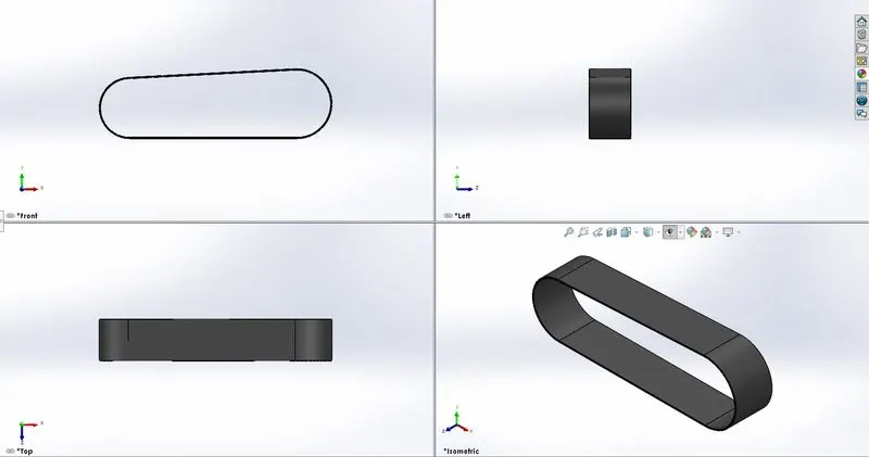
Tools used-
- Line
- Arc
- Trim
- Smart dimension
Feature used-
- Extrude
- fillet
Design procedure-
- Select the midplane
- Sketch the profile by line and arc with required dimension.
- Offset the profile with required dimension.
- Extrude the sketch.
- Change the appearance.
FRONT FENDER
The front fender is used to protect the riders and bike parts from mud, water and dirt which is kicked out by the front wheel.
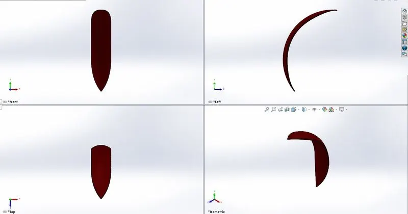
Tools used-
- 3-point Arc
- Spline
- Dynamic mirror
- Offset entities
- Extent entities
- Trim entities
- Smart dimension
Features used-
- Revolve
- Split
- Fillet
Design procedure
- Select the required plane.
- Draw a 3-point arc with required dimension.
- Offset the profile.
- Remove the excess by power trim, complete the sketch by extend entities.
- Select revolve feature to revolve the profile about the axis.
- Mirror the sketch by dynamic mirror.
- Use split tool to get required shape at the end of the fender.
- Use fillet to round the edge.
- Change the appearance.
REAR FENDER
The rear fender is same as the front fender which is attached to the rear wheel.
Tools used-
- 3-point Arc
- Spline
- Dynamic mirror
- Offset entities
- Extent entities
- Trim entities
- Smart dimension
Features used-
- Revolve boss/base
- Split
- Fillet
Design procedure
- Select the required plane.
- Draw a 3-point arc with required dimension.
- Offset the profile.
- Remove the excess by power trim, complete the sketch by extend entities.
- Select revolve feature to revolve the profile about the axis.
- Mirror the sketch by dynamic mirror.
- Use split tool to get required shape at the end of the fender.
- Use fillet to round the edge.
- Change the appearance.
KICKSTAND
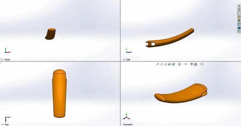
Kickstand is used to support the vehicle at rest.
Tools Used-
- Ellipse
- Spline
- Centre point rectangle
- Smart dimensions
Feature used-
- Lofted boss/base
- Fillet
- Dome
- Extruded cut
- Split
Design Procedure-
- Select the required plane for sketch.
- Draw an ellipse.
- Select the plane normal to the ellipse and draw a spline.
- Draw another ellipse.
- Join them by pierce option.
- Use loft option to connect the two ellipses along the spline.
- Add a dome to both sides.
- Cut-extrude at one side. Draw circle and boss-extrude it at the already cut-extruded side to create a joint for the kick stand with the chassis.
- Remove the bottom part by using split command.
- Add fillet.
- Add appearance.
CHAIN
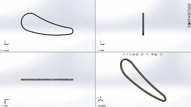
Chain is transmission system which is used to transmit power from engine to the wheel.
Tools used-
- 3-point arc
- Circle
- Trim entities
- Block
- Smart dimensions
Features used-
- Extrude boss/base
- Fillet
- Curve driven pattern
Design procedure
- Select a plane
- Draw a curved sketch path by using circle and arc.
- Chain link 1 and chain link 2 are first sketched by ellipse, circle and arc and then made into blocks.
- Add the block to the part area and extrude them
- Use curve driven pattern tool to pattern them along the curve profile when curve is irregular manually add the blocks.
- Mirror the other side of the chain along the axis.
- Add appearance.
OIL TANK
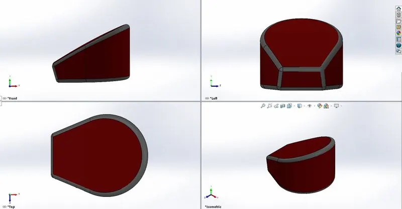
Oil tank is used as reservoir for engine oil. Engine oil is used as lubricant and coolant in engine moving parts.
Tools used-
- Line tool
- 3-point arc
- Spline
- Dynamic mirror
- Smart dimensions
Features used-
- Extrude boss/base
- Combine
- Fillet
- Shell
Design procedure
- Select the required plane.
- Draw the sketch as per the required dimensions.
- Extrude the sketch by giving thickness.
- Draw another sketch at the same plane.
- Extrude the sketch by giving thickness.
- Combine them by using combine option by selecting common parts between them.
- Add fillet.
- Create a hollow space by shell tool.
- Add appearance.
PEDAL
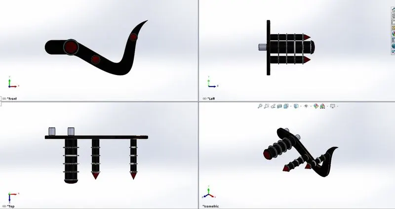
Pedals are footrest which supports the rider’s foot while riding.
Tools used-
- Line tool
- Spline
- Circle
- Offset entities
- 3-point arc
- Smart dimensions
Features used-
- Extrude boss/base
- Revolve boss/base
- Linear pattern
- Dome
- Chamfer
Design procedure
- Select the required plane
- Sketch the required design by using circle, line, spline, and arc commands.
- Extrude the sketch by giving thickness.
- Revolve the sketch by revolve tool.
- Create a dome.
- Draw 2 circle and extrude the sketch by giving thickness.
- Add fillets and chamfer.
- Use linear pattern to create rings around the ring.
- Add appearances.
FRONT WHEEL
Wheel is circular shaped structure, and which is the first and best invention of humankind and it changed the perspective of today’s world. Wheel is the only part which moves the vehicle by rotating on its own axis.in this wheel modelling we model rim, tyre, rotor, and calliper.
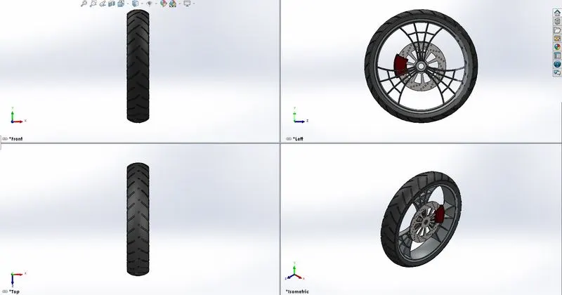
Tools used-
- Line tool
- Spline
- 3-point arc
- Extend entities
- Trim entities
- Sketch fillet
- Smart dimensions
Features used-
- Extrude boss/base
- Revolve boss/base
- Circular pattern
- Chamfer
- Extrude cut
- Combine
- Fillet
Design procedure
- Select the required plane.
- Sketch the profile by using line and arc.
- Revolve the sketch about the axis by revolve tool.
- Draw another sketch using line, circle.
- Extrude the sketch by giving thickness.
- Cut the excess part by cut-extrude and the rim has been created.
- Use circular pattern to create three instances of the rim
- Combine the tyre and rim by combine tool.
- Add fillets.
- Circular sketch is drawn and extrude at offset distance from the center of the rim to the rotor.
- The rotor part is created by changing the circular part using cut extrude and circular pattern.
- Sketch and extrude the brake caliper.
- Tyre is created by creating a sketch a profile and revolving it by revolve tool.
- Threads are created by sketching rectangle and cutting it cut extrude and fillet are added and patterned by circular pattern.
- Sprocket is created by sketching a circular sketch and extruded and cut by cut extrude tool and patterned by circular pattern.
- Appearances are added
REAR WHEEL
Rear wheel is same as the front wheel, but it’s attached to the rear side, and it’s rotated by the power of engine which transmitted through gearbox and chain.
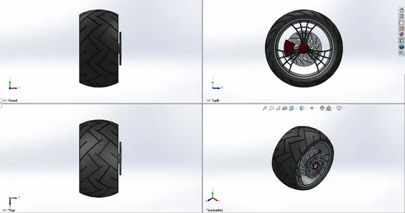
Tools used-
- Line tool
- Spline
- 3-point arc
- Extend entities
- Trim entities
- Sketch fillet
- Smart dimensions
Features used-
- Extrude boss/base
- Revolve boss/base
- Circular pattern
- Chamfer
- Extrude cut
- Combine
- Fillet
Design procedure
- Select the required plane.
- Sketch the profile by using line and arc.
- Revolve the sketch about the axis by revolve tool.
- Draw another sketch using line, circle.
- Extrude the sketch by giving thickness.
- Cut the excess part by cut-extrude and the rim has been created.
- Use circular pattern to create three instances of the rim
- Combine the tyre and rim by combine tool.
- Add fillets.
- Circular sketch is drawn and extrude at offset distance from the center of the rim to the rotor.
- The rotor part is created by changing the circular part using cut extrude and circular pattern.
- Sketch and extrude the brake caliper.
- Tyre is created by creating a sketch a profile and revolving it by revolve tool.
- Threads are created by sketching rectangle and cutting it cut extrude and fillet are added and patterned by circular pattern.
- Sprocket is created by sketching a circular sketch and extruded and cut by cut extrude tool and patterned by circular pattern.
- Appearances are added
FRONT FORK
The fork is a rod which has suspension system which is connected the axle of the front wheel. Fork consists of handlebar, brake liver and head lights.
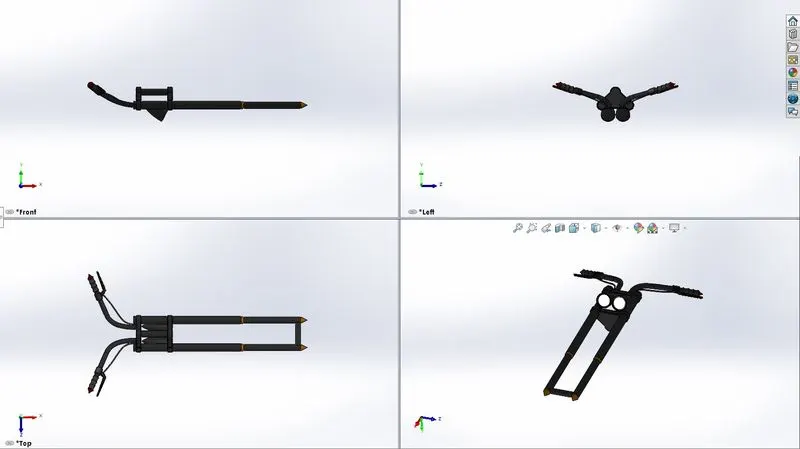
Tools used-
- Line tool
- Spline
- 3-point arc
- Circle
- Convert entity
- Smart dimension
Features used-
- Extrude boss/base
- Revolve boss/base
- Combine
- Fillet
- Mirror
- Movecopy body
- Split
- Sweep boss/base
- Projected curve
Design procedure
- Select the required plane to sketch.
- Sketch the required sketch by line tool.
- Revolve the sketch about the axis by revolve tool to create fork.
- For headlight sketch a profile with required dimension and revolve it and use cut and use dome.
- For handlebar sketch a circle and curves (in different axis and project them) and use sweep to create solid.
- For handle sketch a profile and revolve them.
- For break wire use same procedure as handlebar with different dimension.
- Add fillet where it required.
- Create a reference plane and mirror the whole part and then combine them.
- Create a plane at bottom for reference for assembly
- Add appearance.
CHASIS
The chassis is the skeleton and base structure of the automobiles which holds the entire parts of the model.
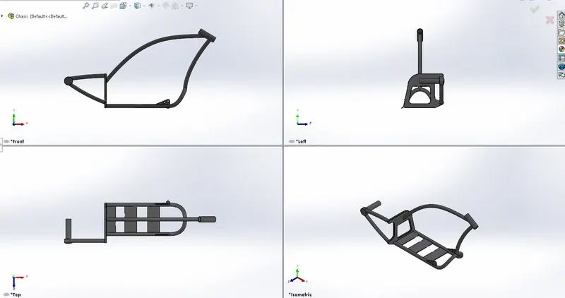
Tools used-
- Line tool
- Spline
- Circle
- Convert entity
- Smart dimension
Features used-
- Extrude boss/base
- Combine
- Fillet
- Mirror
- Split
- Sweep boss/base
- Projected curve
- Dome
- Circular pattern
- Linear pattern
Design procedure
- Select the required plane to sketch.
- Import the sketch picture of chopper into SOLIDWORKS.
- Draw two curves and project them by projected curve them by project curve and sweep them and mirror them about axis.
- Draw a sketch and extrude and cut hole by cut extrude.
- Add fillet.
- Create a new plane and sketch a circle and spline and sweep them remove the internally by split tool.
- For connecting front fork use revolve tool to create another hollow rod.
- Combine them by combine tool.
- For engine support plate sketch a rectangle and extrude.
- Same for pedal and kick stand clamp.
- Add fillets
- Add appearance.
ENGINE
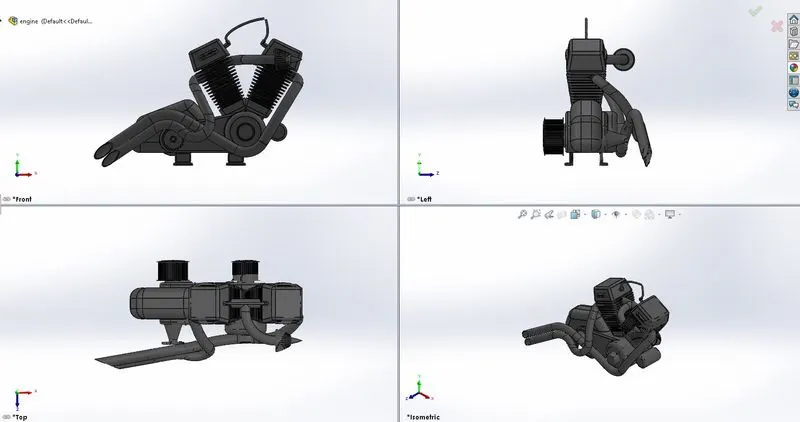
The engine is the heart of an automobile. It converts heat energy into mechanical energy. Engine is a complex machine which consists of several moving and non-moving parts.
Tools used-
- Line tool
- Spline
- 3-point arc
- Offset entity
- Trim entity
- Sketch fillet
- Convert entity
- Smart dimension
Features used-
- Extrude boss/base
- Revolve boss/base
- Combine
- Fillet
- Mirror
- Extrude cut
- Sweep boss/base
- Projected curve
- Composite curve
- Dome
- Circular pattern
- Linear pattern
Design procedure
- Select the required plane for sketch.
- Import the sketch picture of chopper into SOLIDWORKS.
- For engine case sketch a profile by line and circle and extrude. Add fillets for cylindrical structure use revolve.
- For transmission belt lever use revolve and boss extrude and create dome.
- Add fillets and chamfer.
- For engine head create a new plane sketch a profile extrude it and cut it by cut extrude and add fillet, chamfer, and dome.
- For cooling fin sketch profile and cut it pattern it by linear pattern.
- Then mirror the engine head.
- For air intake draw a profile and sweep.
- For air filter is created by revolve and cut extrude and circular pattern
- Then engine exhaust is made by combining 2 projected curves by composite curve and use sweep to model it along the circular path.
- Do the same for another exhaust.
- Use split to modify the end of split.
- Add appearances.
GAS TANK
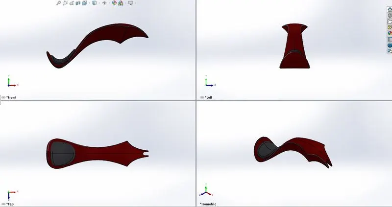
It is a fuel tank which stores fuel and send the fuel to engine. It is an important factor for design it defines the vehicle type.
Tools used-
- Line tool
- Spline
- Convert entity
- Smart dimension
Feature used-
- Swept surface
- Boundary surface
- Loft surface
- Knit surface
- Swept cut
- Shell
- Fillet
Design Procedure-
- Select the required plane for sketch.
- Import the sketch picture of chopper into the SOLIDWORKS.
- For the top profile of the gas tank, create a reference and use surface-sweep to create a profile and surface-trim to remove the excess.
- For the side profile of the gas tank, create a surface by creating two curves in different planes and project them by project curves and use surface-loft tool to create a surface.
- Use mirror tool to mirror the surface along the axis.
- Use knit-surface tool to combine all the surfaces together.
- For creating a seat, sketch the profile and extrude using surface-extrude.
- Close the bottom of the tank by boundary-surface and surface-loft.
- Use knit-surface tool to combine all the surfaces together.
- Add fillets.
- Use the cut-sweep tool to create a cut at the bottom of the gas tank.
- Use the shell tool to create a hollow cavity.
- Change the Appearances.
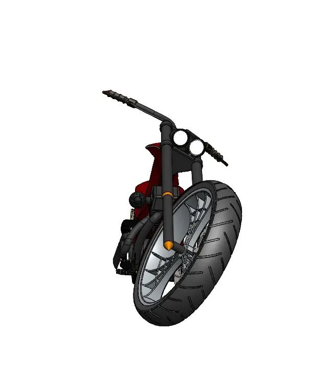
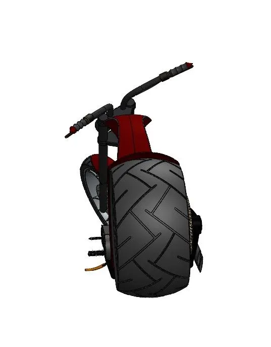
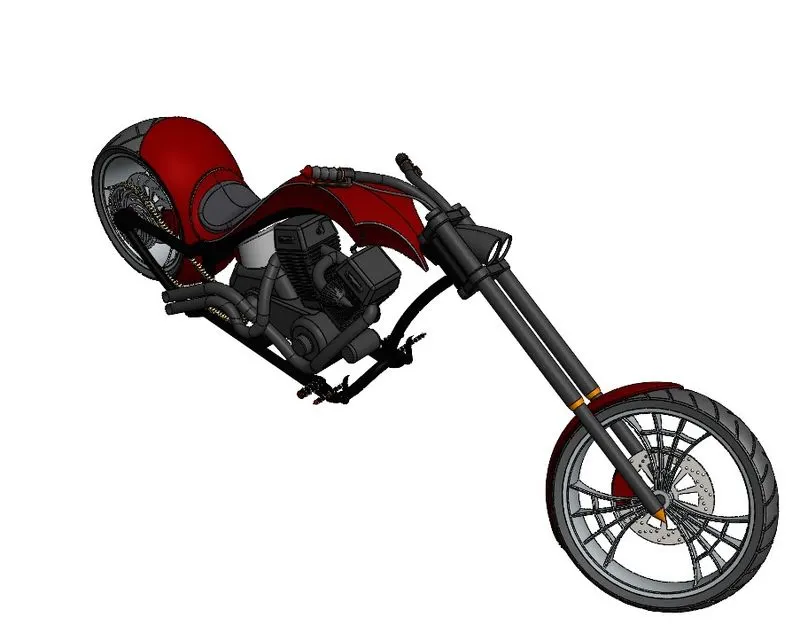
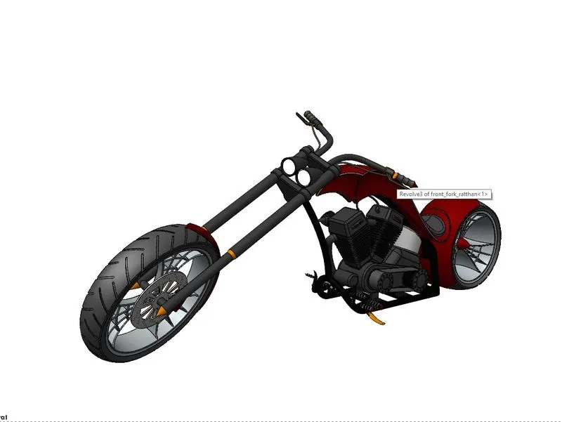
ASSEMBLY OF AMERICAN CHOPPER
The assembly is a feature of SOLIDWORKS which is used to assemble all part models by suitable assembly mates.
There three types of assembly mates
- Standard mates: geometric relations such as perpendicular, parallel, concentric etc.
- Advance mate: in this option we can enter width, angle, linear etc values between the part models components.
- Mechanical mate: this option is used to stimulate the real time interaction such as movements by using Cam, gear, and universal joint.
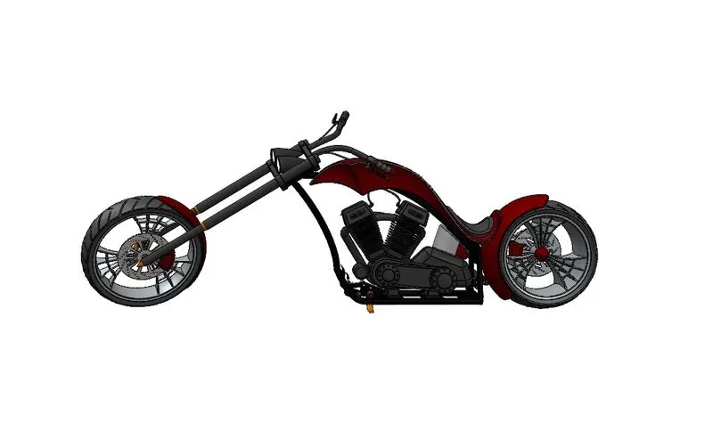
SIDE VIEW
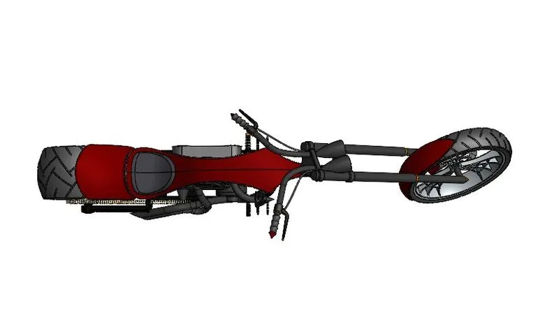
TOP VIEW
FRONT VIEW
BACK VIEW
ISOMENTIC VIEW
CAMERA VIEW
PROCEDURE
- Open SOLIDWORKS and select assembly option.
- First import chassis part file into assembly area and fix it.
- Import all the other model by one by one and mate them by using suitable mates such us coincident, distance, limit angle and tangent etc
- Add suitable appearance and decals
- Then set the assembly model in required camera view.
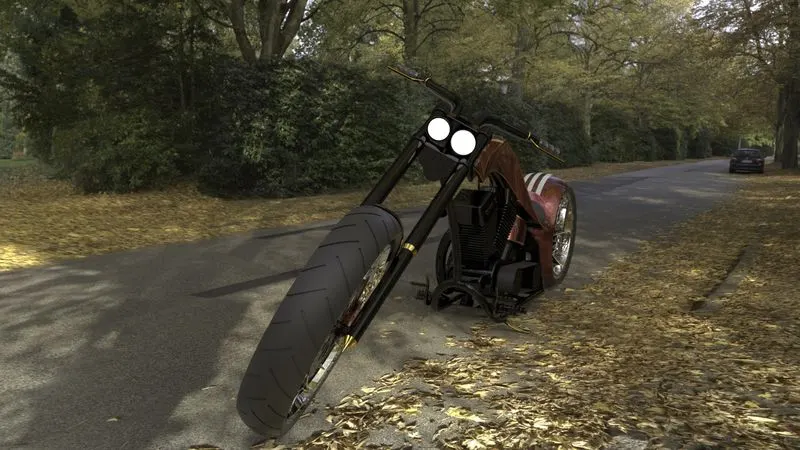
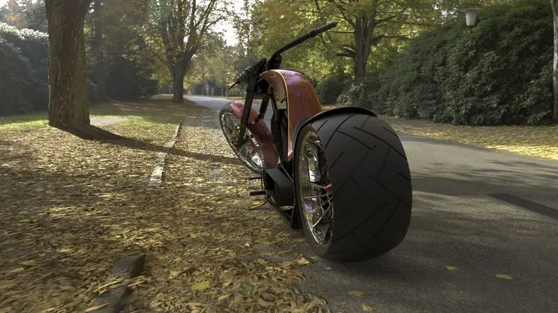
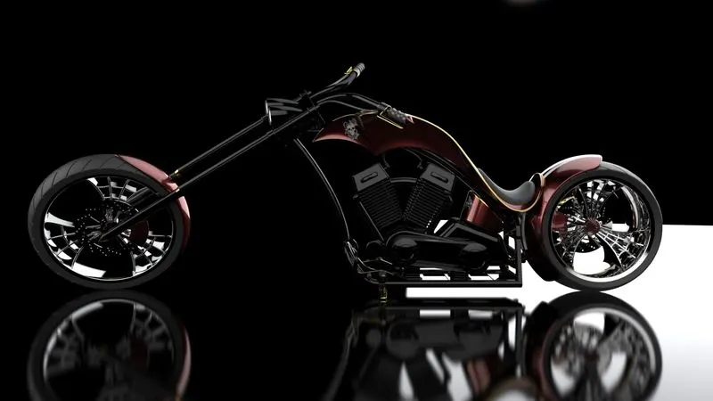
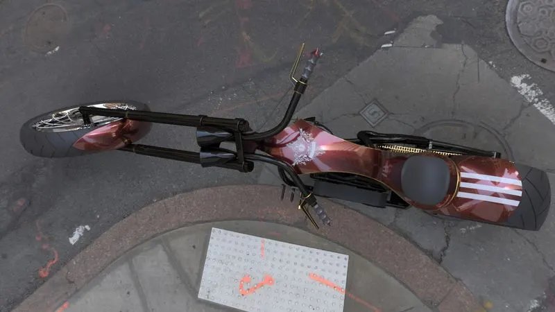
RENDER IMAGE
It is a process of creating realistic imaged of the model in the required environment. Rendering is done in photoview 360 and SOLIDWORKS visualize.
FRONT VIEW
BACK VIEW
SIDE VIEW
TOP VIEW
ISOMETRIC VIEW
CAMERA VIEW
CONCLUSION
American chopper are custom made bikes by the choice of people's taste and while deisgning it improved my knowledge on solid modeling and enhanced my skills in designing aspect.