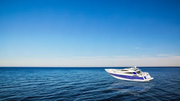
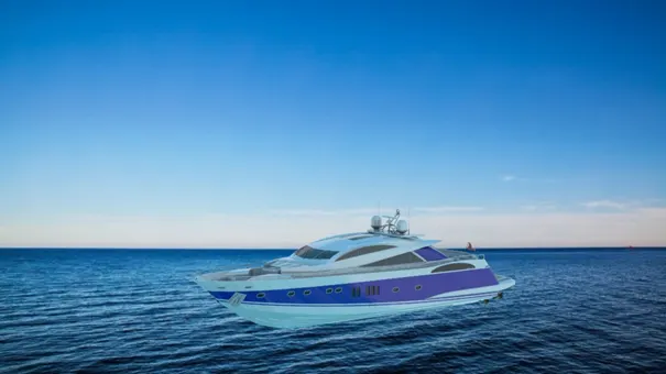
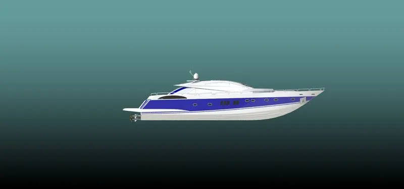
Radar Mast & Final Assembly of Yacht
Radar Mast
Report
Yatch Modelling In SolidWorks
AIM
To sketch and build an entire American Predator Yacht using SOLIDWORKS.
INTRODUCTION
SolidWorks is a solid modelling computer-aided design (CAD) and computer-aided engineering (CAE) computer program. Building a model in SolidWorks usually starts with a 2D sketch. The sketch consists of geometry such as points, lines, arcs, conics and splines. Dimensions are added to the sketch to define the size and location of the geometry. Relations are used to define attributes such as tangency, parallelism, perpendicularity, and concentricity. The parametric nature of SolidWorks means that the dimensions and relations drive the geometry, not the other way around. The dimensions in the sketch can be controlled independently, or by relationships to other parameters inside or outside the sketch.
In an assembly, the analogue to sketch relations is mates. Just as sketch relations define conditions such as tangency, parallelism, and concentricity concerning sketch geometry, assembly mates define equivalent relations concerning the individual parts or components, allowing the easy construction of assemblies. SolidWorks also includes additional advanced mating features such as gear and cam follower mates, which allow modelled gear assemblies to accurately reproduce the rotational movement of an actual gear train.
Designing in Solidworks starts with a 2-dimensional sketch. From a 2D sketch, one can create 3-dimensional objects using built-in tools called “features.” Features are simply different ways of converting 2D outlines into 3D objects. Two of the most common tools (methods) for doing this are extrusions (the “extrude” feature) and revolutions (the “revolve” feature).
Different Parts of a Yatch
- Propeller
- Radar
- Hull
- Garage Door
- Rear Seat
- Middle Seat
- Front Seat
- Superstructure
- Radar Mast
Blueprint Setup
Blueprint acts as a reference for 2-D sketching, from this blueprint one can easily understand what´s the initial step he/she have to do. Below figure.1 shows the yatch blueprint we used for modelling.
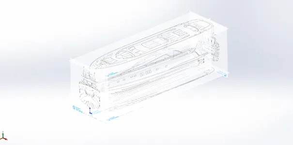
Figure 1: Blueprint Setup
Propeller
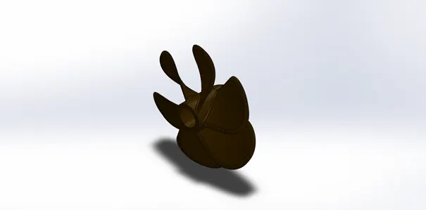
Features used:
- Sketch spline
- Revolve
- Reference Geometry
- Bose/Base Loft
- Fillet
- Extrude Cut
- Circular Pattern
Radar
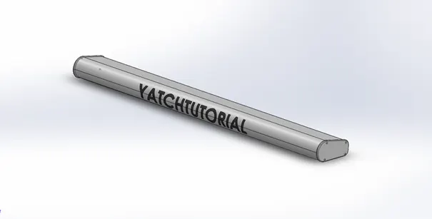
Features used:
- Sketch
- Extrude
- Fillet
- Offset entities
- Pattern/Mirror
- Cut extrude
- Sketch entities > Text
- Curve > Split Line
- Appearance
Hull
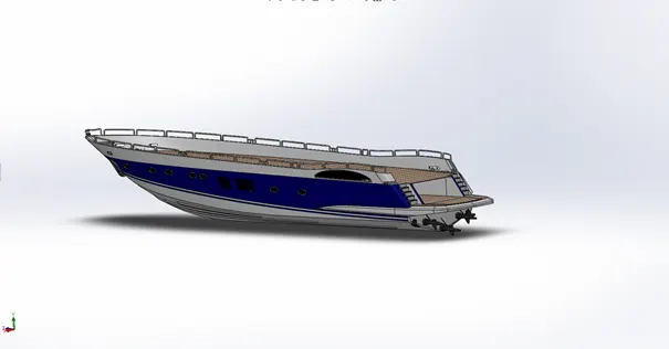
Features used:
- Blueprint setup
- Sketch
- Projected curve
- Surface loft
- Surface trim
- Surface extrude
- Surface knit
- Surface fill
- Try to form Solid
- Shell feature
- Fillet
- Pattern feature
- Boss extrude
- Chamfer
- Boss/Base > Sweep
- Split body
Garage Door
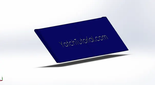
Features used:
- Sketch
- Extrude cut
- Shell
- Fillet
- Mirror
- Sketch entities > Text
- Solid Bodies
Rear Seat
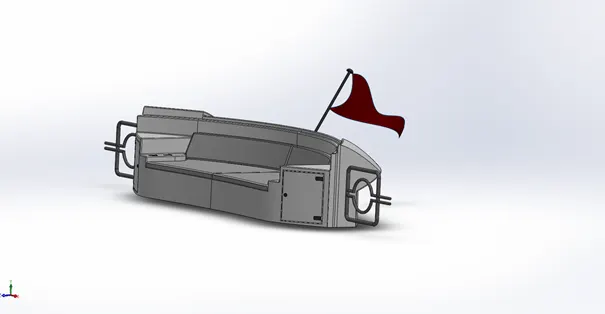
Features used:
- Sketch
- Surface Offset
- Ruled surface
- Surface Knit
- Surface Extend
- Surface trim
- Surface extrude
- Surface Loft
- Chamfer
- Fillet
- Boss/Base >Sweep
- Mirror
- Revolve
Front Seat
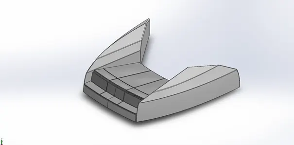
Features used:
- Sketch
- Surface sweep
- Surface extrude
- Surface trim
- Surface loft
- Surface knit
- Surface fill
- Chamfer
- Boss/Base >Revolve
- Extrude cut
- Fillet
- Pattern/ Mirror
- Dome Feature
Middle Seat
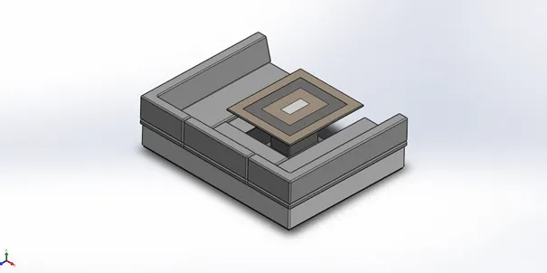
Features used:
- Sketch
- Boss/Base > Extrude
- Chamfer
- Extrude cut
- Surface Knit
- Fillet
- Pattern / Mirror
Super Structure
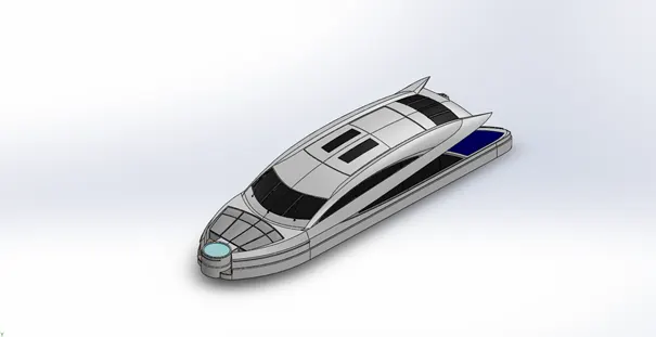
Features used:
- Sketch
- Surface Extrude
- Surface Sweep
- Surface Knit
- Fillet
- Ruled Surface
- Surface trim
- Surface loft
- Surface extend
- Boss extrude
- Dome feature
- Boss/Base Sweep
- Extrude cut
- Chamfer
- Project Curve
- Mirror Feature
- Make into Solid Feature
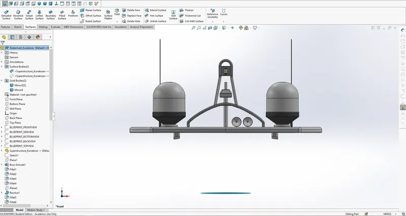
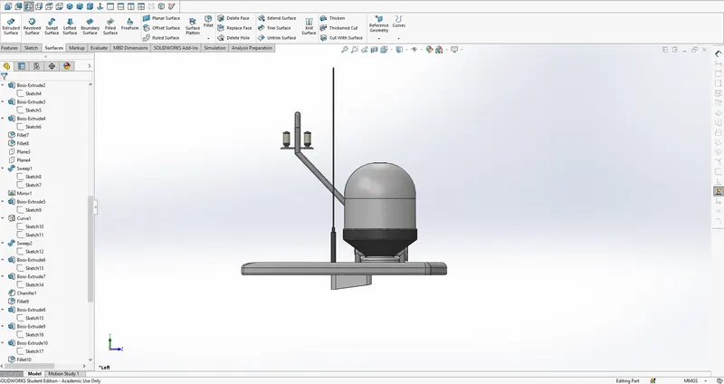
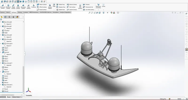
Radar Mast
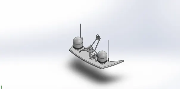
Features used:
- Sketch
- Boss Extrude
- Fillet
- Boss/Base Revolve
- Boss extrude
- Boss/Base sweep
- Project Curve
- Chamfer
- Mirror
- Dome Feature
Assembly
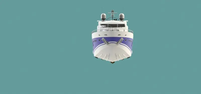
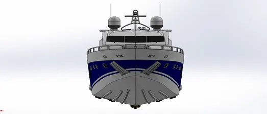
Front View
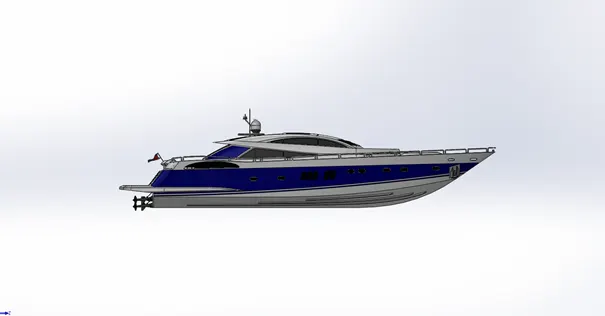
Side View
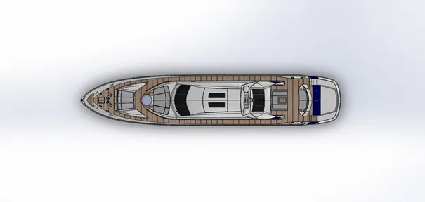
Top View
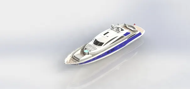
Isometric View
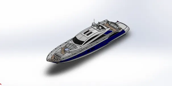
Rendering in Photoview 360