FINAL INDEPENDENT PROJECT
Modelling Crawler Excavator in Solidworks
AIM
To design and build an entire Crawler Excavator using SOLIDWORKS.
ABSTRACT
This project presents an overview of the process involved in modelling a feasible and operational CAD model of an Excavator using SolidWorks premium 2020. Concurrently, it details the procedure of modelling each part and the assembly in the Solidworks.
INTRODUCTION
SolidWorks is a solid modelling computer-aided design (CAD) and computer-aided engineering (CAE) computer program. Building a model in SolidWorks usually starts with a 2D sketch. The sketch consists of geometry such as points, lines, arcs, conics and splines. Dimensions are added to the sketch to define the size and location of the geometry. Relations are used to define attributes such as tangency, parallelism, perpendicularity, and concentricity. The parametric nature of SolidWorks means that the dimensions and relations drive the geometry, not the other way around. The dimensions in the sketch can be controlled independently, or by relationships to other parameters inside or outside the sketch.
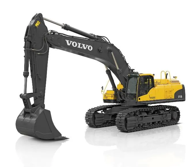
Figure 1: Shows the Crawler Excavator
Excavators are engineering works created through the moving or processing of parts of the earth's surface involving quantities of soil or unformed rock. The earth may be moved to another location and formed into the desired shape for a purpose. Modern excavators carried out using earthmoving diggers – which are heavy construction equipment consisting of a boom, stick (ram and ram-body), bucket and cab on a rotating platform. The cab sits atop an undercarriage with tracks. All movements of the digger are accomplished through the use of hydraulic fluid, with hydraulic cylinders and hydraulic motors.
Due to the cost and complexity involved in designing such large machines as excavator, it is necessary to establish a medium by which the quality, efficiency and real-world applicability of such machines can be estimated before production. Doing this would help the manufacturer with design validation, redesigning and essentially save time and cost of production. One such
significantly applicable medium is virtual modelling on CAD software. Modelling helps validate and visualize the physical representation of the machine.
Designing in Solidworks starts with a 2-dimensional sketch. From a 2D sketch, one can create 3-dimensional objects using built-in tools called “features.” Features are simply different ways of converting 2D outlines into 3D objects. Two of the most common tools (methods) for doing this are extrusions (the “extrude” feature) and revolutions (the “revolve” feature).
METHODOLOGY
With the Solidworks software, each part of the machine is independently recreated and then assembled to form the full model of the Crawler Excavator.
Modelling
Each component of the machine was modelled in Solidworks using geometries that aggregate to a complete representation of the component. The major functional component for this machine is the bucket, the arm, the boom, turret bed, cabin and the undercarriage.
Bucket
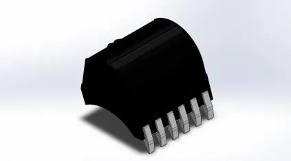
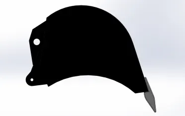
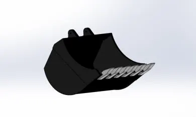
Figure 2: Bucket generated in Solidworks
Bucket: A compartment that collects materials, soil, or rubbish and dumps them to the required position.
Features used :
• Sketch
• Boss-Extrude
• Cut- Extrude
• Fillet
• Offset entities
• Shell
• LPattern
• Mirror
The Arm: The arm is a solid link connecting the bucket and the boom.
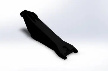
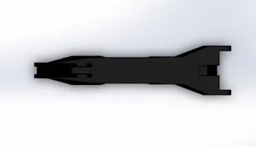
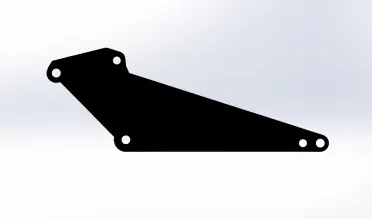
Features used :
• Sketch
• Boss-Extrude
• Cut- Extrude
• Fillet
• Offset entities
• Shell
• Mirror
• Loft
• Revolve Cut
• Reference Plane
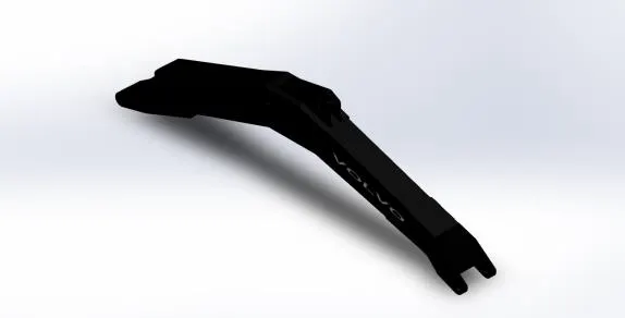
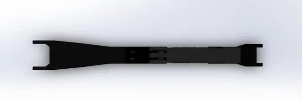
The Boom: The boom serves as the muscle that does the lifting and the lowering of the Arm, the bucket and the rubbish.
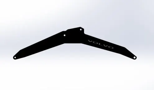
Features used :
• Sketch
• Boss-Extrude
• Cut- Extrude
• Fillet
• Offset entities
• Shell
• Mirror
• Loft
• Revolve Cut
• Reference Plane
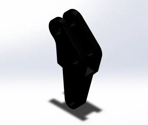
Bucket Linkage: This is one of the most important parts of the mechanism by which all the digging forces are transmitted from the ground to the boom via bucket linkage.
Features used :
• Sketch
• Boss-Extrude
• Cut- Extrude
• Fillet
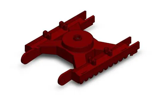
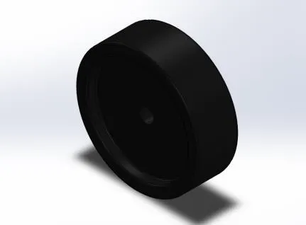
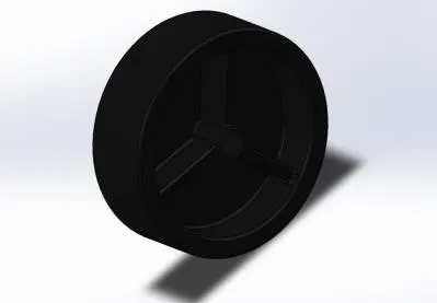
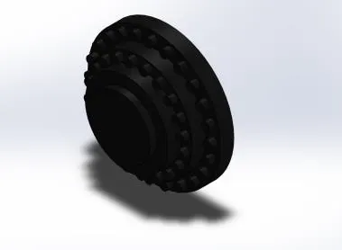
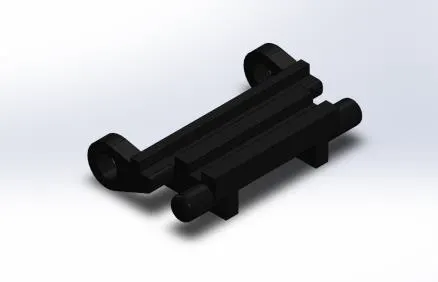
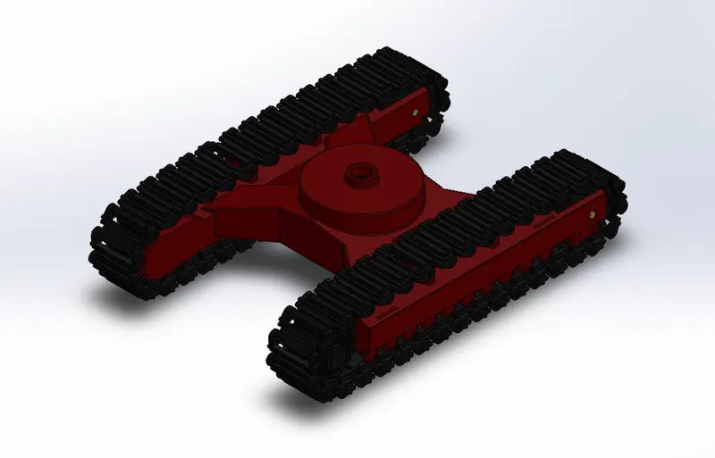
The Undercarriage: The undercarriage is the supporting framework underneath any vehicle. Any wheel or tracks get attached or fitted to the undercarriage to help your machine move.
Features used :
• Sketch
• Boss-Extrude
• Cut- Extrude
• Fillet
• Offset entities
• Shell
• Mirror
• Revolve Cut
• Reference Plane
• Circular pattern
The wheel (driven), wheel driving and the wheel cap all assembled to the undercarriage frame. The final assembly of the undercarriage is shown below.
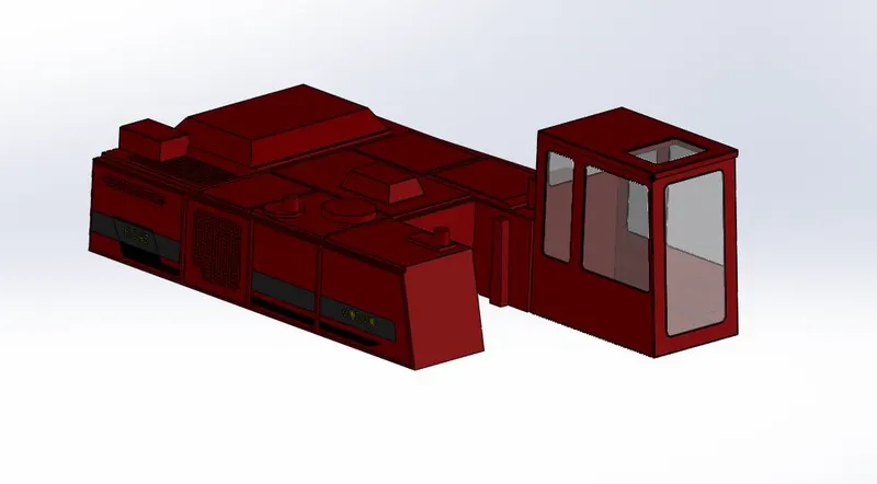
The cabin: The main purpose of the application of the cabin is to increase the safety and comfort of the operator during work.
Features used :
• Sketch
• Boss-Extrude
• Cut- Extrude
• Fillet
• Offset entities
• Shell
• Mirror
• Reference Plane
• Chamfer
• Split line
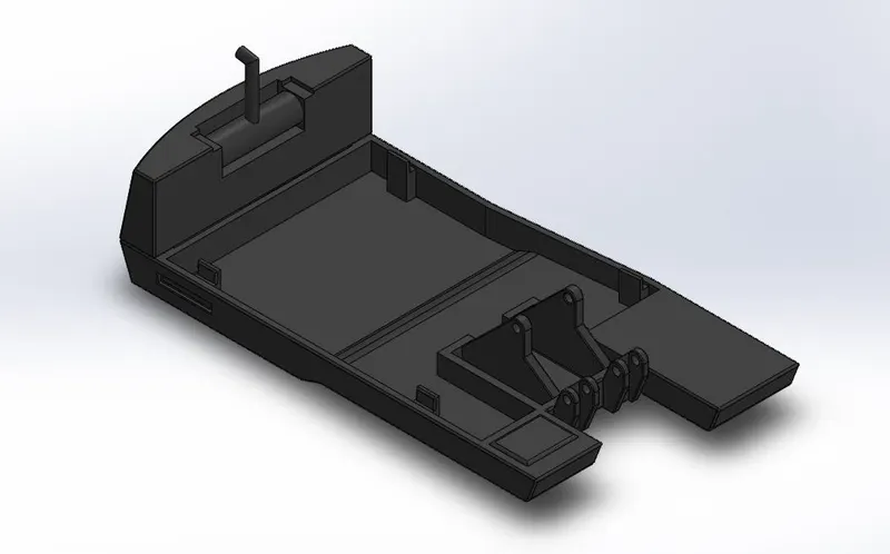
Turret Bed: The engine, cabin, boom and hydraulics are mounted to this turret bed.
Features used :
• Sketch
• Boss-Extrude
• Cut- Extrude
• Fillet
• Offset entities
• Shell
• Mirror
• Reference Plane
• Chamfer
• Split line
• Loft
• Sweep
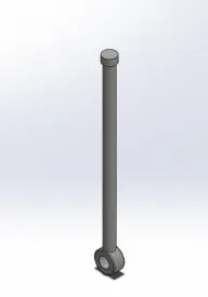
Hydraulic system: The hydraulic system of an excavator consists of a pump, valve cylinder and piston etc.
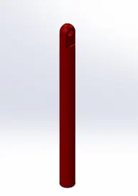
Features used :
• Sketch
• Boss-Extrude
• Cut- Extrude
• Revolve cut
• Fillet
Final assembly of the Crawler Excavator
First, the turret bed is mated to the assembled undercarriage. Then the cabin was attached to the turret bed after some angle rotation and mating. The bucket, arm, boom and hydraulics system are all connected together to the turret bed.
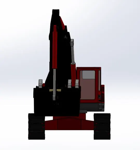
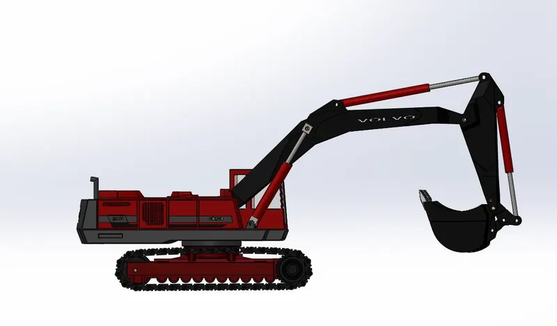
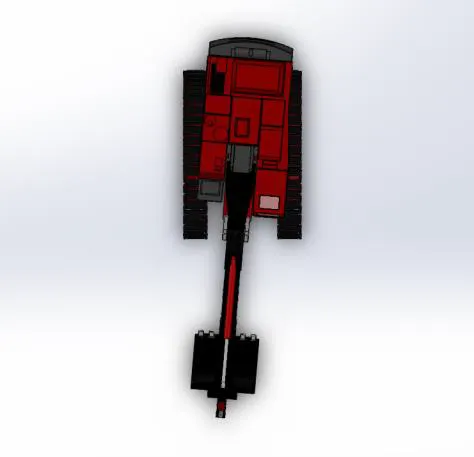
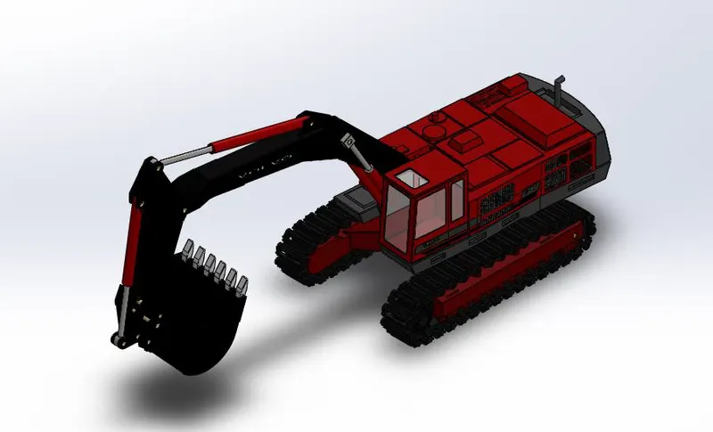
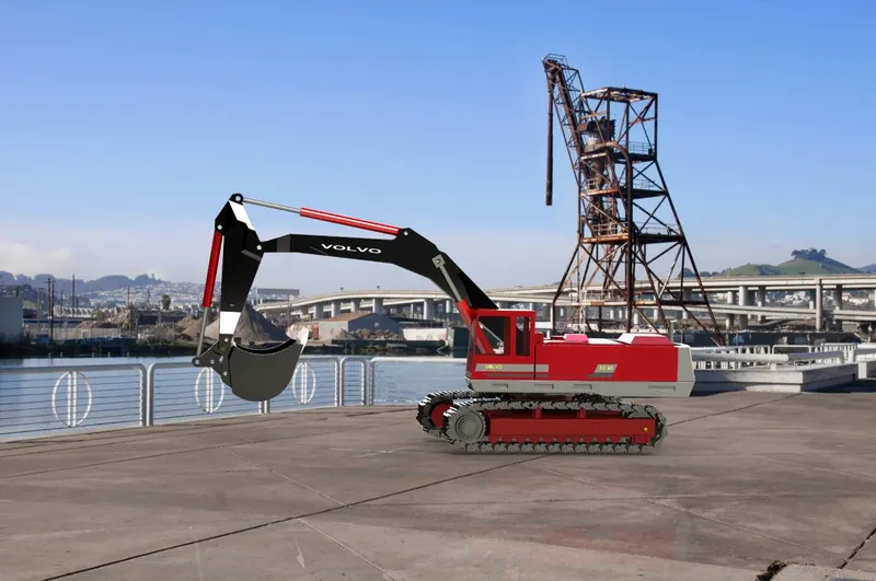
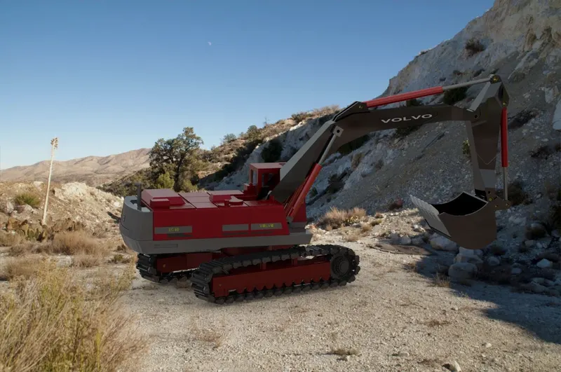
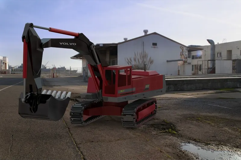
Photo-Realistic Rendering
PROJECT SCOPE
• When more depth of digging is a need, the digging depth with a crawled machine will be more because the undercarriage sits lower than compared to a wheeled machine.
• The bucket teeth function as soil breaking parts by penetrating the media. The shape of the tooth facilitates a penetration process by providing proper pressure continues to push itself into the soil media. So some changes in the design of the tooth can decrease the penetration pressure and then the digging time will be reduced.
• By doing designing projects like this will give an ability to think and implement new ideas and working principle.
CONCLUSION
SolidWorks is a solid modelling computer-aided design and computer-aided engineering computer program. This project helped me to sketch and build a complete Crawled Excavator along with the photo-realistic renders using Solidworks.
REFERENCE
1. Mehta Gaurav, K. 2008. “Design and Development of an Excavator Attachment”. M. tech Dissertation Thesis. Nirma University, Institute of Technology: Ahmadabad.
2. Luengo, O., S. Singh, and H. Cannon. 1998. “Modeling and Identification of Soil-Tool Interaction in Automated Excavation”. Proceedings of the 1998 IEEE/RSJ International Conference on Intelligent Robots and Systems. Victoria, BC, Canada.1900-1906.