Photo Realistic Rendering
Designing an American Chopper in Solidworks
OBJECTIVE
- To design and assemble the parts of an American Chopper in Solidworks
- To do the photorealistic rendering using Photoview 360 or Solidworks visualize
INTRODUCTION
SolidWorks is a solid modelling computer-aided design (CAD) and computer-aided engineering (CAE) computer program. Building a model in SolidWorks usually starts with a 2D sketch. The sketch consists of geometry such as points, lines, arcs, conics and splines. Dimensions are added to the sketch to define the size and location of the geometry. Relations are used to define attributes such as tangency, parallelism, perpendicularity, and concentricity. The parametric nature of SolidWorks means that the dimensions and relations drive the geometry, not the other way around. The dimensions in the sketch can be controlled independently, or by relationships to other parameters inside or outside the sketch.
In an assembly, the analogue to sketch relations is mates. Just as sketch relations define conditions such as tangency, parallelism, and concentricity concerning sketch geometry, assembly mates define equivalent relations concerning the individual parts or components, allowing the easy construction of assemblies. SolidWorks also includes additional advanced mating features such as gear and cam follower mates, which allow modelled gear assemblies to accurately reproduce the rotational movement of an actual gear train.
DESIGN METHODOLOGY
Designing in Solidworks starts with a 2-dimensional sketch. From a 2D sketch, one can create 3-dimensional objects using built-in tools called “features.” Features are simply different ways of converting 2D outlines into 3D objects. Two of the most common tools (methods) for doing this are extrusions (the “extrude” feature) and revolutions (the “revolve” feature).
Extrusions: The Extrude feature takes a 2D sketch in the x-y plane and gives it thickness or depth by developing it linearly in the z-axis. For example, a sketch of a circle would be extruded into a cylinder.
Revolutions: The Revolve feature takes a 2D sketch in the x-y plane and gives it thickness or depth by rotating it about one of the two sketch axes (i.e. the x or y-axis).
DESCRIPTION
Parts Designed - Tools/ Features used while designing
- Transmission Belt
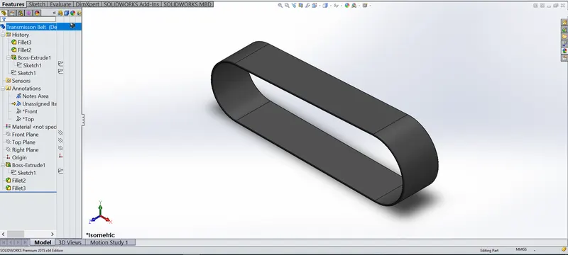
Sketch - The sketch is the basis for a 3D model. We can create a sketch on any of the default planes (Front Plane, Top Plane, and Right Plane), or a created plane. We can also create a sketch on a flat surface, a spline on a surface, or the face of a solid. We can change the plane or face on which a sketch is created.
Offset - Offset entities takes a copy of your existing geometry and copies it at an offset. Instead of recreating geometry, we can use this to quickly sketch based on model geometry. Offset entities is a great tool for enlarging or shrinking your sketch geometry.
Bosss Extrude – An Extruded Boss/Base feature will allow you to take a 2D sketch and add thickness to it in the third dimension.
Fillet - creates a rounded internal or external face on the part. We can fillet all edges of a face, selected sets of faces, selected edges, or edge loops.
- Kickstand
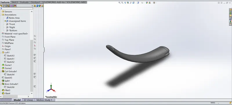
Reference Plane – It is used to create a reference plane by selecting a reference point to sketch.
Loft - creates a feature by making transitions between profiles. A loft can be a base, boss, cut, or surface. You create a loft using two or more profiles.
Dome – Creates a concave shape to the selected surface.
Cut Extrude – To create cut on the 3D profile.
Split - to create multiple parts from an existing part. We can create separate part files, and form an assembly from the new parts. We can split one or more solid or surface bodies.
- Front fender
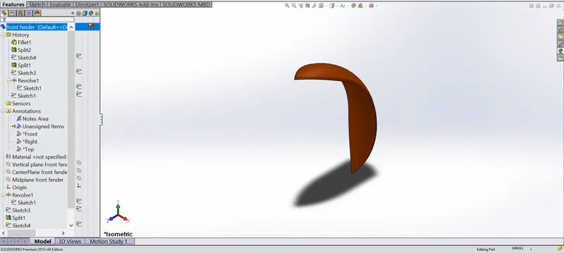
Reference Geometry - create an external reference when one document is dependent on another document for its solution.
Revolve – Revolves add or remove material by revolving one or more profiles around a centerline. We can create revolved boss/bases, revolved cuts, or revolved surfaces. The revolving feature can be a solid, a thin feature, or a surface.
Trim Entities – It is used to remove extra lines from the sketch.
Dynamic Mirror - similar to mirror entities however the line or lines to mirror about are selected beforehand then anything drawn in the sketch will be mirrored dynamically.
- Rear fender
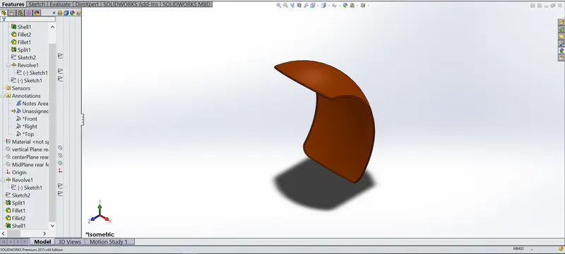
Sketch
Revolve
Trim Entities
Split
Shell - The shell tool hollows out a part, leaves open the faces we select, and creates thin-walled features on the remaining faces.
- Oil Tank
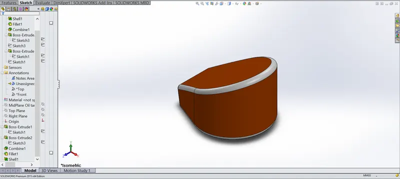
Sketch
Boss Extrude
Fillet
Shell
Combine – To combine created two bodies.
- Chain
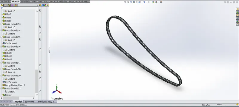
Sketch
Boss Extrude
Fillet
Curve Pattern- The Curve Driven Pattern tool allows we to create patterns along a planar or 3D curve.
Block - We can make, save, edit, and insert blocks for drawing items and sketch entities that we use often, such as standard notes, title blocks, label positions, and so on. We can attach blocks to geometry or to drawing views, and we can insert them into sheet formats.
Mirror- The ability to mirror can be found in part and assembly files, and allows you to mirror sketch entities, features, faces, bodies, and components.
- Pedal
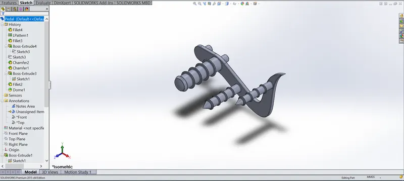
Sketch
Boss Extrude
Fillet
Linear Pattern - We can use linear patterns to create multiple instances of one or more features that we can space uniformly along one or two linear paths. Pattern instances inherit the visual properties of the original feature when we select Propagate Visual Properties in the PropertyManager.
Dome
Chamfer - The chamfer tool creates a bevelled feature on selected edges, faces, or a vertex.
- Front-wheel
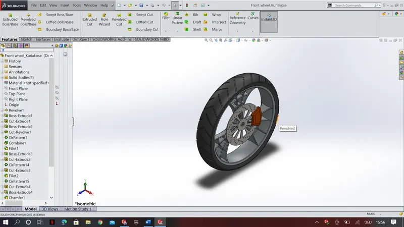
Sketch
Boss Extrude
Fillet
Revolve
Trim
Revolve Cut
Cut Extrude
Circular Pattern
Circular Pattern
- Rear-wheel
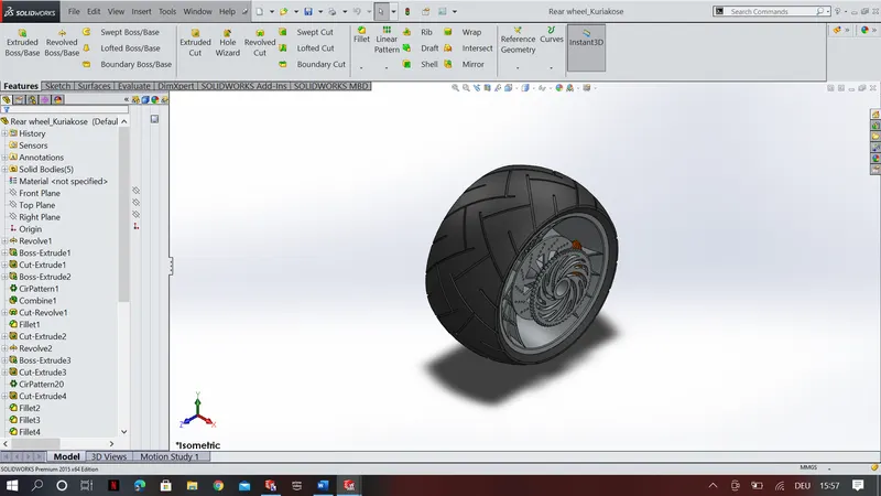
Sketch
Boss Extrude
Fillet
Revolve
Trim
Revolve Cut
Cut Extrude
Circular Pattern
Circular Pattern
- Front fork
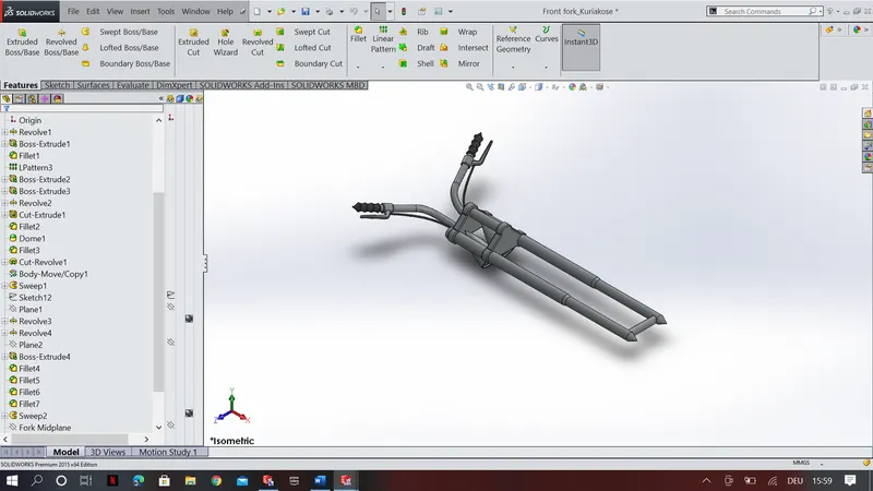
Sketch
Boss Extrude
Fillet
Revolve
Trim
Split
Cut Extrude
Dome
Reference Geometry
Mirror
Combine
Projected Curve- Use this selection to create a curve that represents the intersection of sketches from two intersecting planes. ... Select Bi-directional to create a projection that extends on both sides of the sketch. The two sketches (gray) project onto each other to form the 3D curve (green). The curve is used as a path for a sweep.
Convert Entities - The Convert Entities tool allows users to make a copied projection of a given sketch, face, or set of edges onto the active sketch plane. These sketch entities will update their size and/or positioning if either of these characteristics changes in the source sketch.
- Chassis
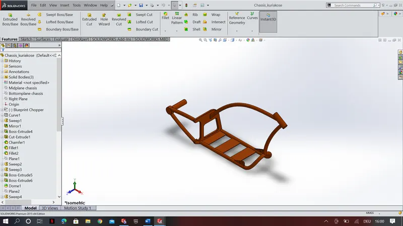
Sketch
Boss Extrude
Fillet
Revolve
Trim
Split
Cut Extrude
Dome
Reference Geometry
Mirror
Combine
Projected Curve
Convert Entities
- Engine
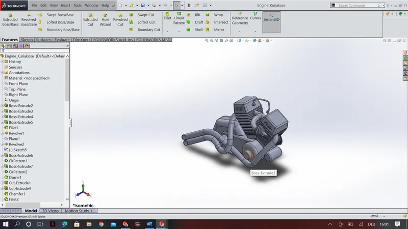
Sketch
Boss Extrude
Fillet
Revolve
Trim
Split
Cut Extrude
Dome
Reference Geometry
Mirror
Combine
Projected Curve
Composite curves - We can create composite curves by combining curves, sketch geometry, and model edges into a single curve. Use a composite curve as a guide curve when creating a loft or a sweep. Click the items (sketch entities, edges, and so on) that we want to join.
- Gas tank
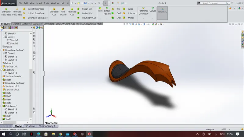
Surface Sweep – It will help to create a 3d figure from a section of the curve along a path.
Surface Trim – Used to trim the extra areas.
Surface Loft - It is the simplest way to allow the software to interpolate a shape between two or more profiles. It works with solids and surfaces, and it has unique functions as well as some overlap with the Boundary feature.
Boundary Surface - The boundary surface feature lets to create surfaces that can be tangent or curvature continuous in both directions (all sides of the surface). In most cases, this delivers a higher quality result than the loft tool.
Surface Knit - Use the Knit Surface tool to combine two or more faces and surfaces into one. Knit surfaces absorb the surface bodies we used to create them.
Fill surface - The Filled Surface feature constructs a surface patch with any number of sides, within a boundary defined by existing model edges, sketches, or curves, including composite curves. We can use this feature to construct a surface to fill a gap in a model.
CHOPPER ASSEMBLY
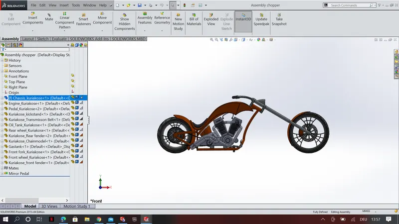
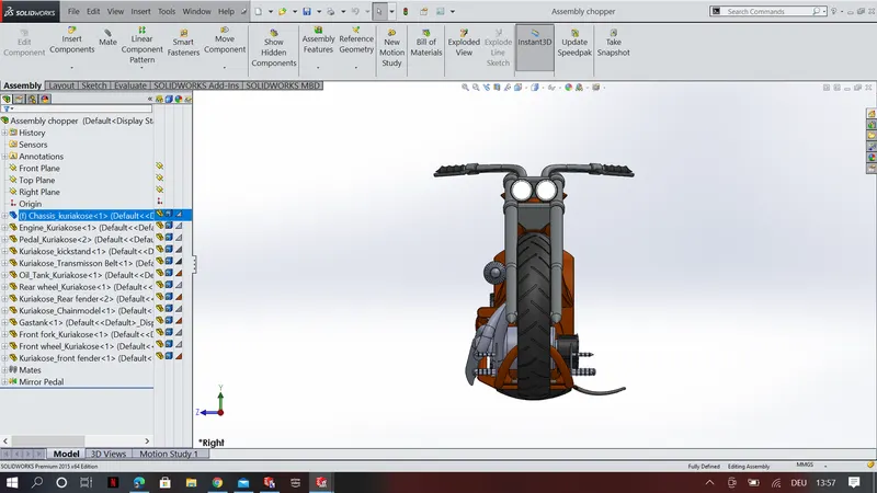
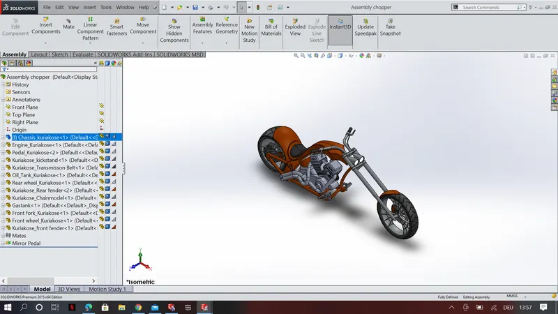
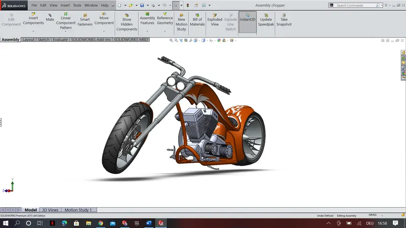
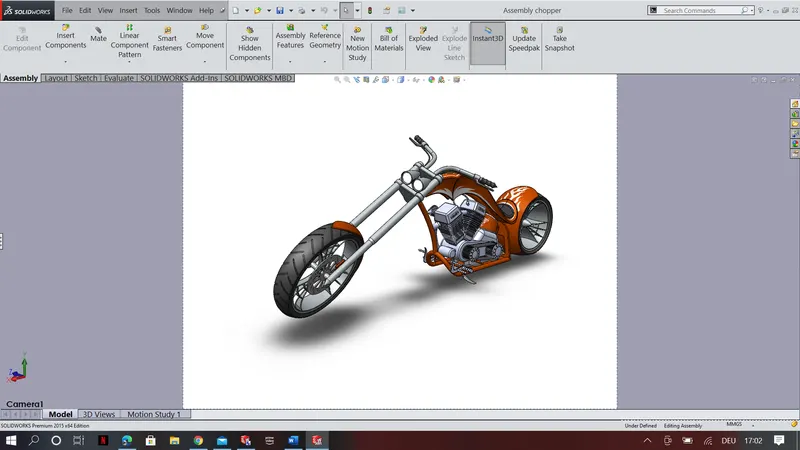
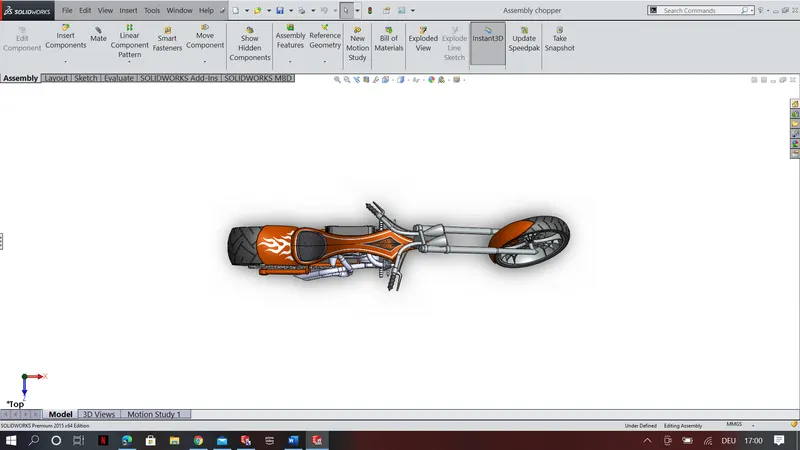
The parts which we created are finally assembled in Solidworks. At first, the Chassis is inserted and all other parts were attached to the chassis using some features.
Features / Tools used for this were :
Insert Part - Use Insert Part to insert a base part into another part document. When we insert a part into another part: The part into which we insert it becomes a multibody part. The part we insert becomes a solid body.
Mate - Mates create geometric relationships between assembly components. As we add mates, we define the allowable directions of linear or rotational motion of the components. We can move a component within its degrees of freedom, visualizing the assembly's behaviour.
Types of mates used in the assembly:
Coincident
Concentric
Angle
Width
Parallel
Distance
Tangent
PHOTO VIEW 360 RENDERING
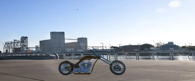
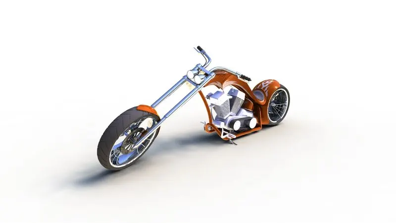
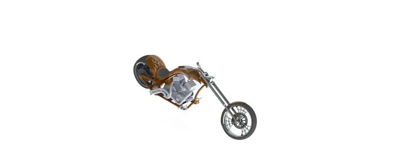
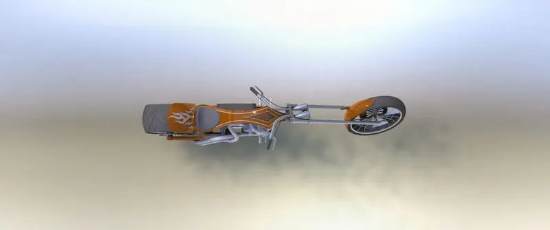
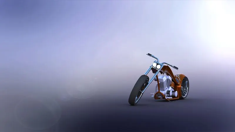
PhotoView 360 is a SOLIDWORKS add-in that produces photo-realistic renderings of SOLIDWORKS models. The rendered image incorporates the appearances, lighting, scene, and decals included with the model.
Front View, Side View, Isometric View, Camera Setup View, and Top View
CONCLUSION
SolidWorks is a solid modelling computer-aided design and computer-aided engineering computer program. This project helped me to sketch and build a complete road-ready Harley Davidson bike using SOLIDWORKS. This also helps to learn how to create cut extrudes, revolve cuts, lofts, circular patterns for modelling - Setting up of reference planes - curve generation - projected curve creation understanding how to insert the parts in assembly workspace - Creation of mates - Difference between float and fix parts - Width mates application. In the end, I also learned how to create photorealistic renderings with realtime appearances and views.