Radar Mast & Final Assembly of Yacht
Designing and Rendering of a Yatch
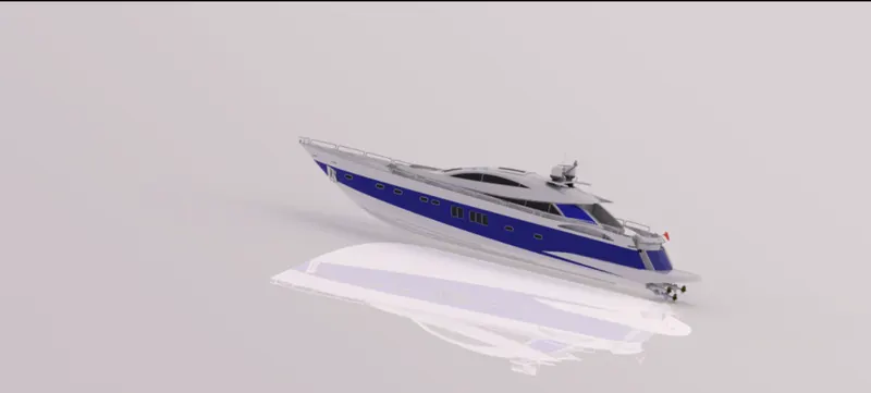
Objective: To assemble a yacht and render it with proper views and environments.
Introduction: In this project, we learn about how we can go about creating a Modern Yacht for studying different tools and features of the SOLIDWORKS. During the design of each part, efforts were made to use each and every tool in SOLIDWORKS and to get familiarized with it.
Design Methodology:
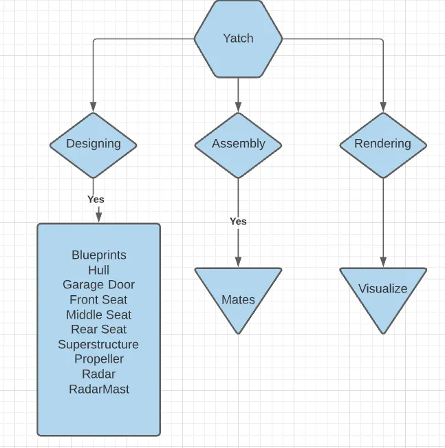
Description:
Parts Created:
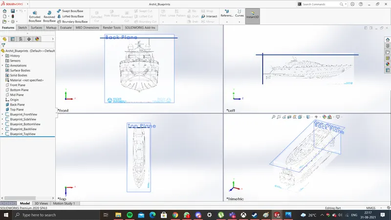
- Blueprints
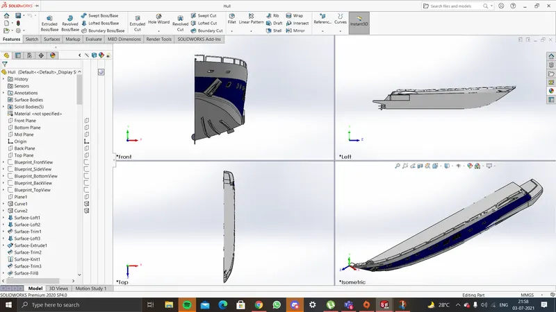
- Hull
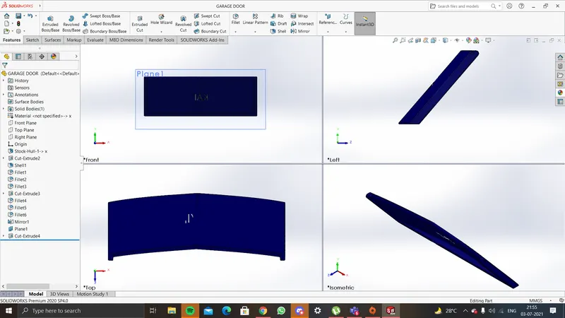
- Garage Door
- Front Seat
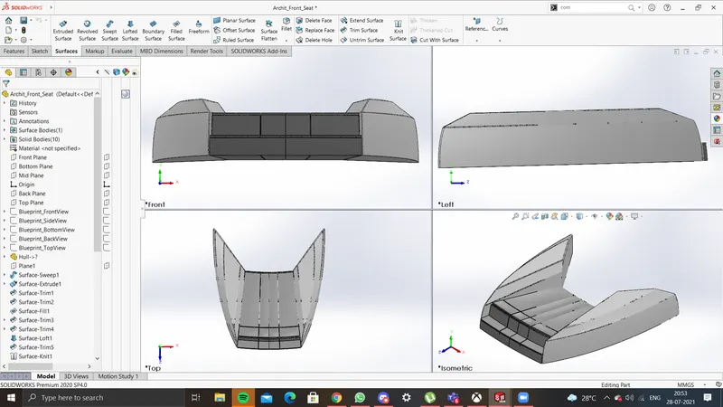
- Middle Seat
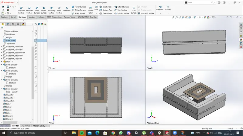
- Rear Seat
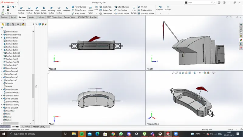
- Superstructure
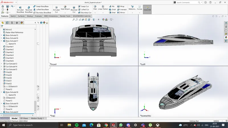
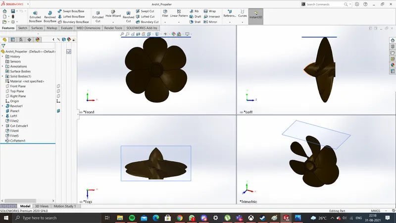
- Propeller
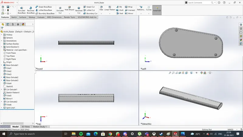
- Radar
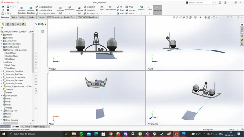
- RadarMast
Features Used:
SKETCH
Sketch is a two-dimensional representation for converting 2D sketch to 3D modeling. In solid works, there are different sketch options to create a sketch and these are known as sketch entities-Line, Circle, Spline, Rectangle, and Arc
EXTRUDE BOSS/BASS
This feature is to convert 2D into solid modeling only when the 2D sketch is completely closed. It also allows extruding the surface in both directions and also offset it to require distance.
REVOLVED BOSS/EXTRUDED
Create a sketch with a centerline, a plane, or an axis for revolve.
EXTRUDE CUT
It is used to remove materials from a solid model in desired patterns and also it can be extruded in both directions.
FILLETS
This is to create a curved surface on the profile edges of the solid model by selecting the required lines or the face. This fillet also has a feature to select multiple lines which reduces time consumption.
CHAMFER
It is similar to the fillet feature but in chamfer, it cuts the solid model intersection area into recurred length and angle.
SPLIT TOOL
This tool is very handy when two or more solid bodies intersect in between or intersect each other. The split tool allows to delete unwanted body formation and gives a clean look.
TRIM ENTITIES
There are 2 entities:
Extend entities: - which allows the broken lines to intersect each other and this can be done only in the 2D sketch.
Trim entities:- this helps to remove the unwanted extended lines with are intersecting.
DYNAMIC MIRROR
To make the solid body identical to each other this feature is used.
COMBINE
Combine feature is used to combine two or more bodies when intersecting to each other and make it a single body.
COMPOSITE CURVE
When the two curve profile is broken this composite curve helps to join and make it a complete smooth single curve.
LINEAR PATTERN
This feature is used to create a different number of patterns required to create the linear pattern.
CIRCULAR PATTERN
This feature is used to create a different number of patterns required to create the circular pattern.
LOFT
The Loft feature allows you to generate complex geometry. It does this by interpolating surfaces between the various cross-sections of the model. These cross-sections can be sketches, faces, or edges. In the Loft interface, the cross-sections are considered as Loft profiles.
DOME
This feature is majorly applied to faces. Select one or more planar or non-planar faces. You can apply domes to faces whose centroid lies outside the face. This allows you to apply domes to irregularly shaped contours.
SHELL
It is used to create the thickness of the profile.
FILL SURFACE
The fill surface feature constructs a surface path with any number of sides within a boundary defined by existing model edges, sketches, or curves including composite curves.
SURFACE TRIM
Primarily used to cut away material from a surface and provides two modes standard and mutual
SURFACE KNIT
Surface knit is used to knit two free edges / open edges of the surface together. Also, it reduces the gap between the two edges of the surfaces.
EXTRUDED SURFACES
You can create extruded surfaces from models that include 2D or 3D faces and knit the extruded surfaces to surrounding features.
REVOLVED SURFACE
Choose different sketches from intersecting or non-intersecting sketches to create the revolve with the Selected Contours pointer.
OFFSET SURFACE
To offset a surface to a certain distance.
SWEPT SURFACE
Surface generated from section curve positioned along the path.
EXTEND SURFACE
To extend a surface by selecting an edge, multiple edges, or a face.
RULED SURFACES
The Ruled Surface command creates surfaces that extend out in a specified direction from selected edges.
DELETE FACE
With the Delete Face tool, you can do the following:
1)Delete: Deletes a face from a surface body, or deletes one or more faces from a solid body to create surfaces.
2)Delete and Patch: Deletes a face from a surface body or solid body and automatically patches and trims the body.
3)Delete and Fill: Deletes faces and generates a single face to close any gap.
REFERENCE PLANE
A feature used to create new planes for sketching.
HELIX/SPIRAL
For creating a spring-like shape in a SKETCH.
MATES
Mates create a geometric relationship between the assembly components. As we add mates, we define the allowable directions of linear or rotational motion of the components. We can move a component within its degree of freedom, visualizing the assembly behavior.
FINAL ASSEMBLY
- Front, Side, Top & Isometric
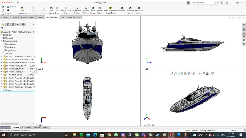
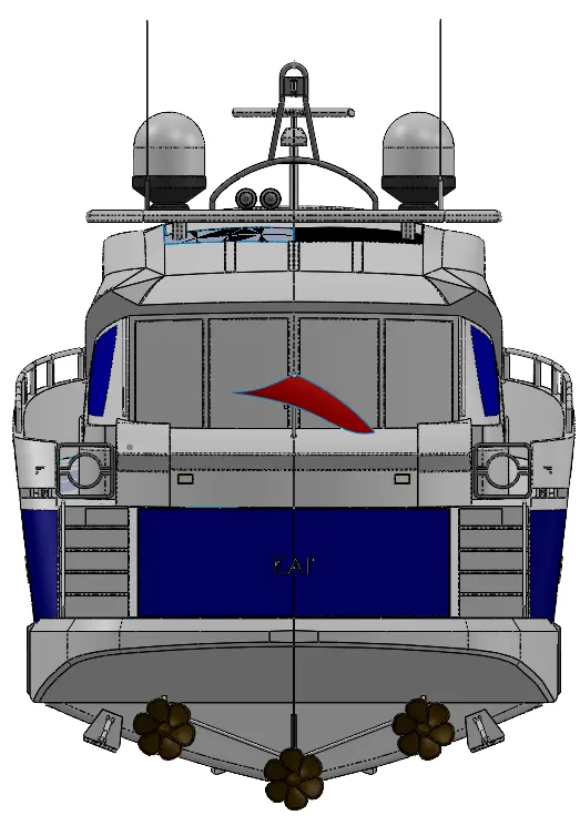
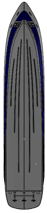
- Back & Bottom
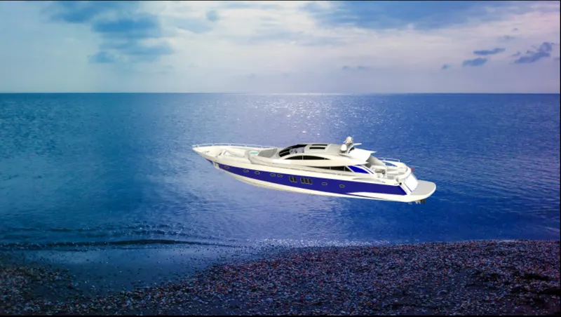
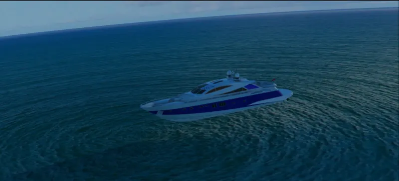
RENDERED IMAGES

Conclusion:
In this project, we learn a lot about how to design using surface and sketch tools, assemble and render in a Solidworks environment.