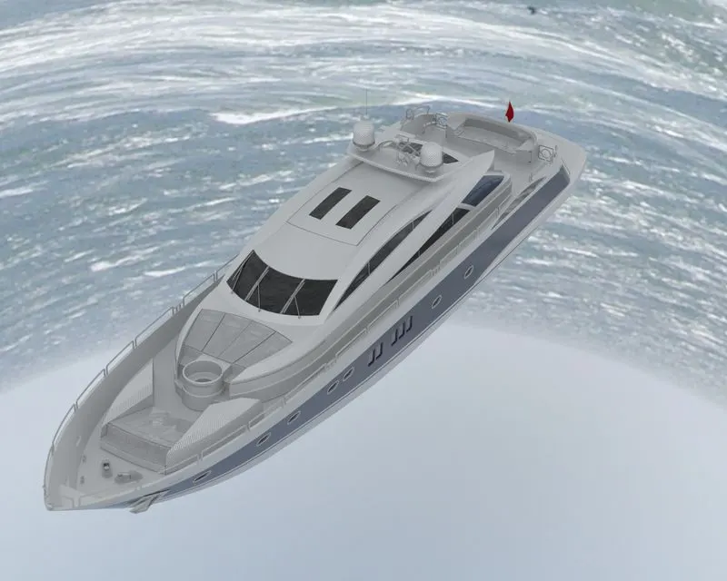
Radar Mast & Final Assembly of Yacht
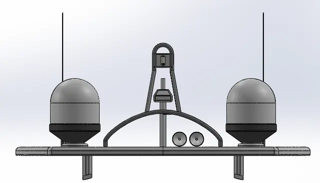
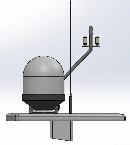
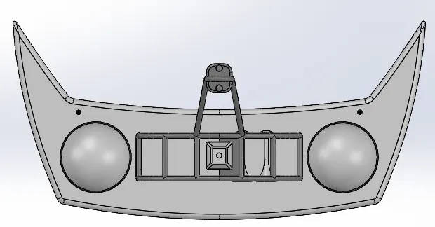
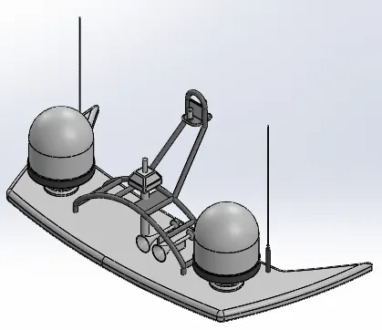
Radarmast
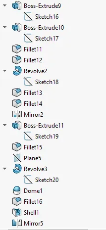
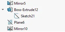
Yacht Assembly Report
PROJECT REPORT
MODELLING OF SUNSEEKER PREDATOR YACHT IN SOLIDWORKS
BY
SUVADEEP GHOSH
INTRODUCTION
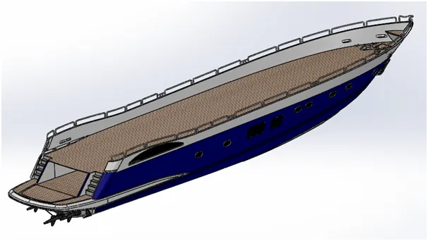
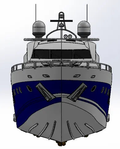
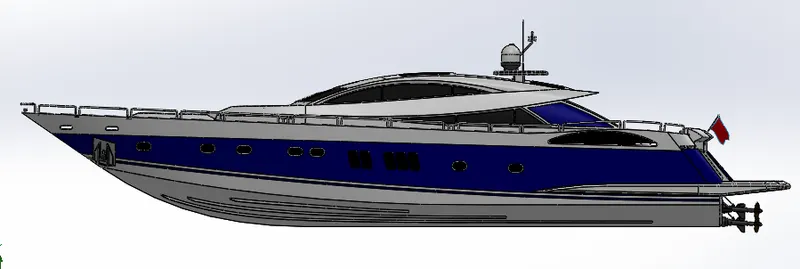
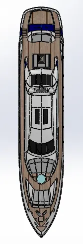
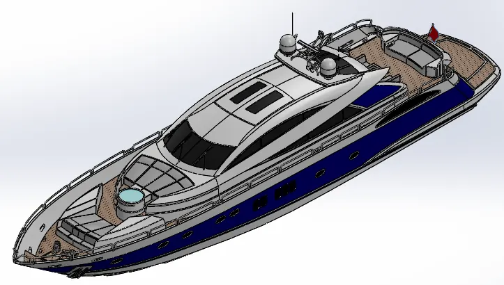
In this project, different cosmetic components for a yacht are designed and assembled as a whole system depicting the external view of an yacht model in SolidWorks. The assembly is rendered using SolidWorks Visualize to resemble a photo-realistic model of a chopper.
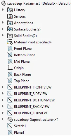
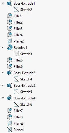
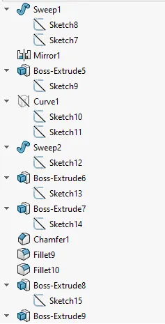
MODELLING & ASSEMBLING FEATURES
The various modelling features used for modelling the Yacht are discussed as follows:
· EXTRUDE:
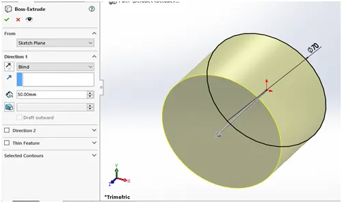
It is a basic tool in Solidworks which converts a 2D sketch in to a 3D model with respect to its geometry in normal direction. First we have to draw a fully closed 2D sketch and then extrude it by defining its starting point, ending point, contours and direction of extrusion.
· REVOLVE:
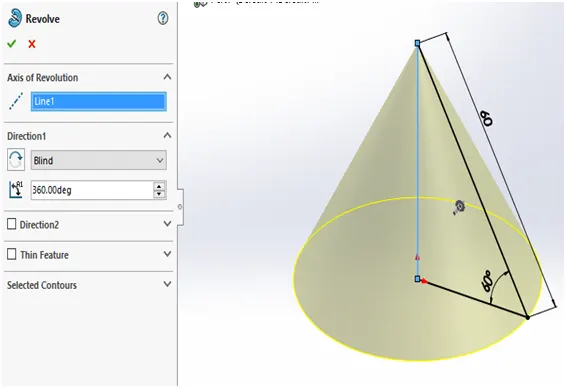
The revolve feature is used to revolve a 2D sketch along an axis or centerline and makes it a 3D model. A 2D sketch is drawn and revolved by selecting a line as a reference for axis of rotation and defining the angle of rotation.
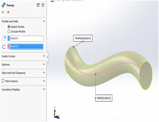
· SWEEP:
A sweep tool is used to sweep a closed 2D sketch along an open or closed path. This tool is generally used for making tubes and bars. A closed loop and a path to sweep are required.
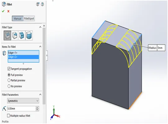
· FILLET:
A fillet is a tool used to round an edge, vertex or face on both inside and outside of a 2D or 3D model. The fillet type, location and radius of the fillet are defined.
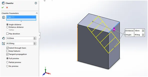
· CHAMFER:
A chamfer is used to remove a sharp edge by creating a sloped edge, vertex or face. Distance and angle of the chamfer are defined.
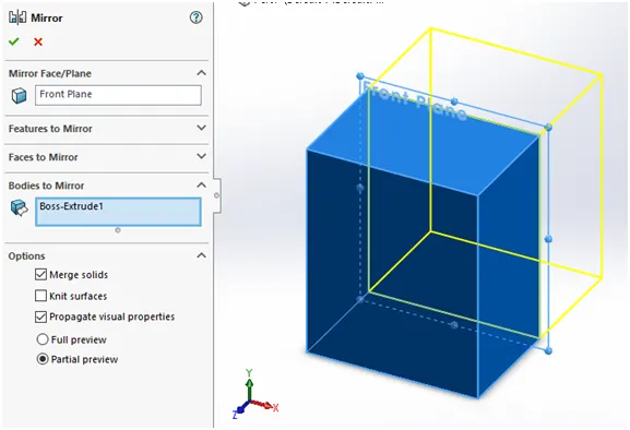
· MIRROR:
Mirror tool in solidworks is used to copy a 2D or 3D object about a reference line or plane. We can have either only the mirrored object or both the original and mirrored objects.
· SHELL:
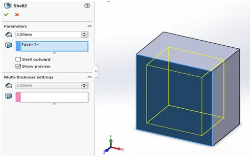
The shell tool hollows out a part, leaves open the faces you select, and creates thin-walled features on the remaining faces. If you do not select any face on the model, you can shell a solid part, creating a closed, hollow model. You can also shell a model using multiple thicknesses. The thickness of the shell is defined.
· LINEAR & CIRCULAR PATTERN:
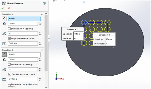
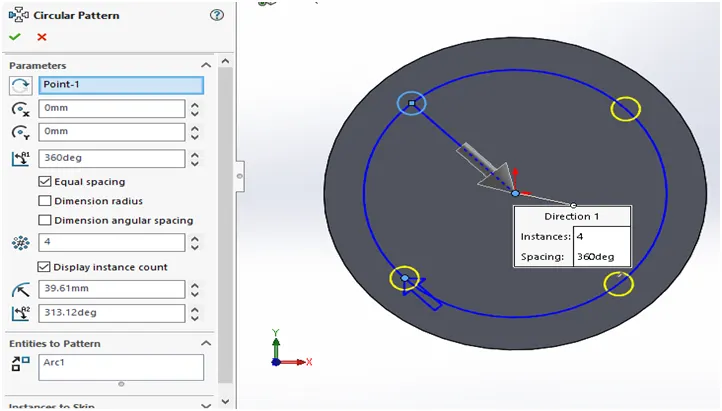
The Linear Pattern Command is used to drive features, faces, or bodies in a linear direction. The Circular Pattern Command is an excellent tool used to replicate features, faces, or bodies in a rotational manner about an axis.
- SURFACE EXTRUDE
This tool is used to convert a 2D sketch into a surface. It can also be used to extrude surfaces from 2D or 3D geometry. First we have to draw a fully closed 2D sketch and then extrude it by defining its starting point, ending point, contours and direction of extrusion.
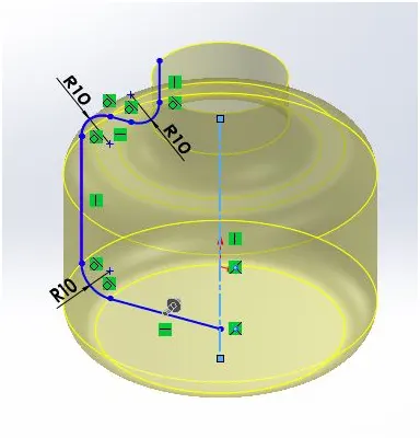
- REVOLVED SURFACE
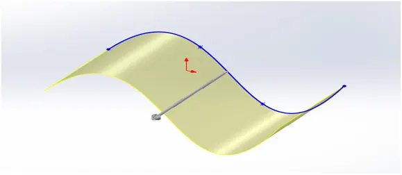
The revolve feature is used to revolve a 2D sketch along an axis or centerline and makes it a solid surface. A 2D sketch is drawn and revolved by selecting a line as a reference for axis of rotation and defining the angle of rotation.
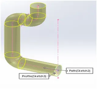
- SWEPT SURFACE
A sweep tool is used to sweep a closed 2D sketch along an open or closed path. This tool is generally used for making closed thin geometry. A closed loop and a path to sweep are required.
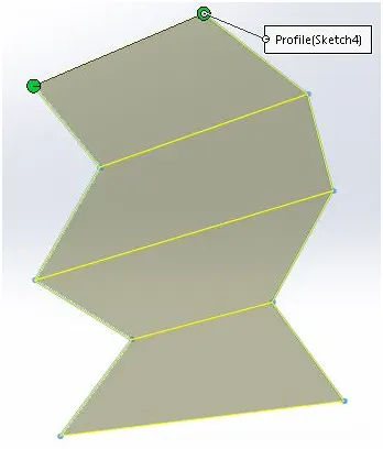
- LOFTED SURFACE
Lofted surface tool is used to create a surface between two non-perpendicular geometry such as 2D curves or premade surfaces. Additionally guide curves can be used anywhere in the feature to make sure the loft follows a specific geometry.
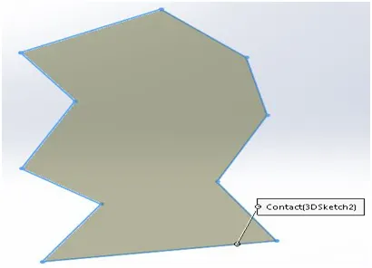
- FILLED SURFACE
Filled surface tool is used to create a surface in a space where all the boundary surfaces are predefined by a 2D geometry or premade curves and this feature simply fills in the surface between the boundaries defined.
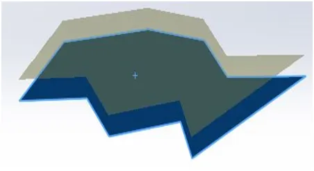
- OFFSET SURFACE
Offset surface is a tool that creates a new surface exactly similar with the reference of a predefined surface geometry and the perpendicular distance between the surface to be newly created. This is a useful tool for created multiple layers of the same geometry with some gap.
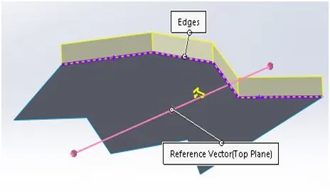
- RULED SURFACE
Ruled surface feature is used to create a variety of surfaces with the reference of a plane. The reference can be tangency, perpendicular or others. Angular offset can also be given while using this feature.
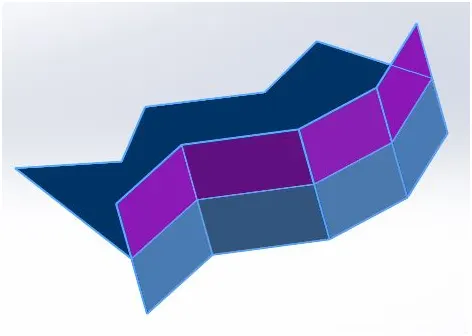
- TRIM SURFACE
Trim surface is used to cut or trim surfaces at the intersection line between two or more surfaces which happen to coincide in their geometry. Selections can be made to either keep a particular geometry and remove everything else intersecting it and vice versa.
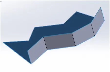
- KNIT SURFACE
This feature is used to merge or knit two or more very close lying surface geometries. This will form one unified surface out of two or more close lying independent surfaces.
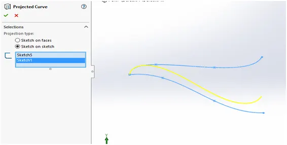
· PROJECTED CURVES:
A projected curve is a 3D curve that represents the intersection of two extruded surfaces of two sketches on intersecting planes.
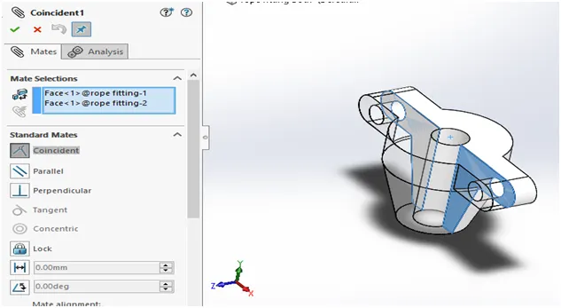
· MATES:
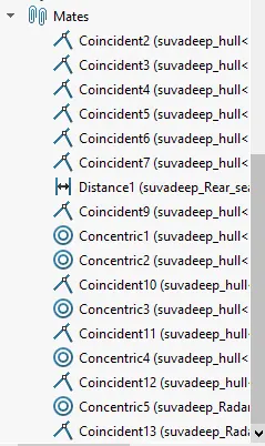
Mate operation is the basic tool for assembling the parts. There are various mate operations such as coincident, parallel, perpendicular, tangent, concentric, lock, etc. We can mate two faces by defining distance or angle between them. Most commonly used mates are coincident mate, concentric mate, distance mates etc.
PARTS CREATED FOR THE PROJECT
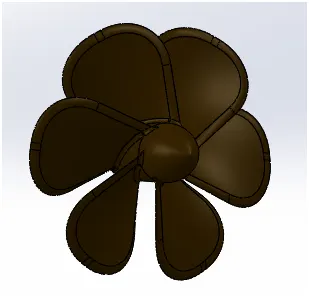
- PROPELLER
To be attached at the backside of the project. Used for the linear movement of the yatch on the water surface.
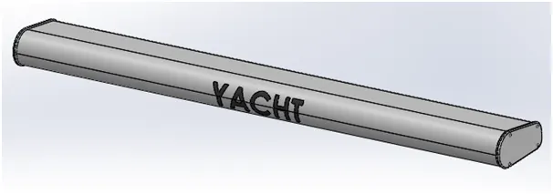
- RADAR
To be attached at the top of the structure. Used for communication and mapping of the waterbody for obstructions.
- HULL
It is the main substructure and forms the main floating body as well as the base upon while the other components are affixed.
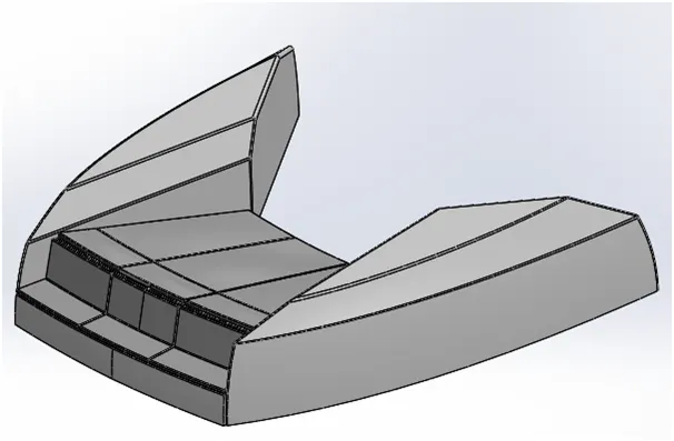
- FRONT SEAT
Attaches at the front portion of the hull
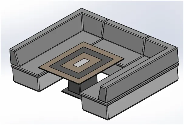
- MIDDLE SEAT
Attaches at the middle portion of the hull
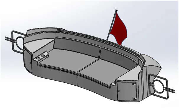
- REAR SEAT
Attaches at the rear portion of the hull
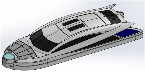
- SUPERSTRUCTURE
To be attached on top of the hull. This provides living space as well as base for attaching the radarmast
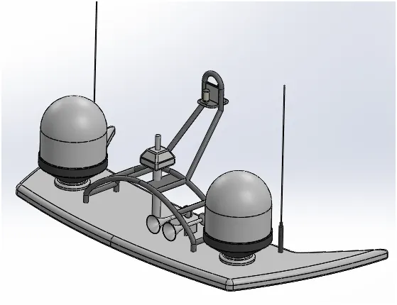
- RADARMAST
To be attached at the top of the structure. Used for communication and mapping of the waterbody for obstructions.
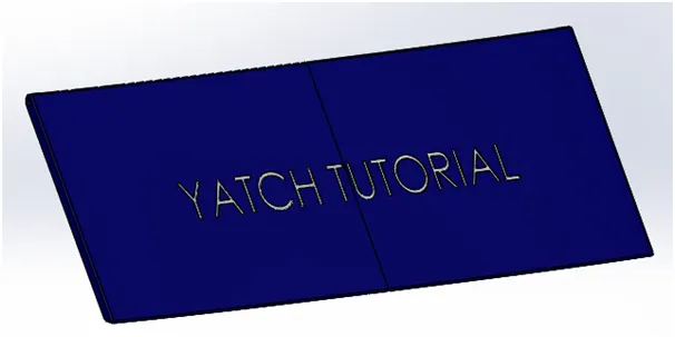
- GARAGE DOOR
To be attached at the back of the hull. Used for enclosing a storage space.
DESIGN APPROACH
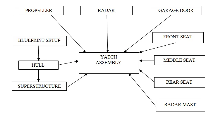
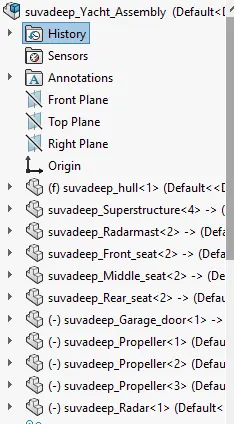
ASSEMBLY
RENDERS
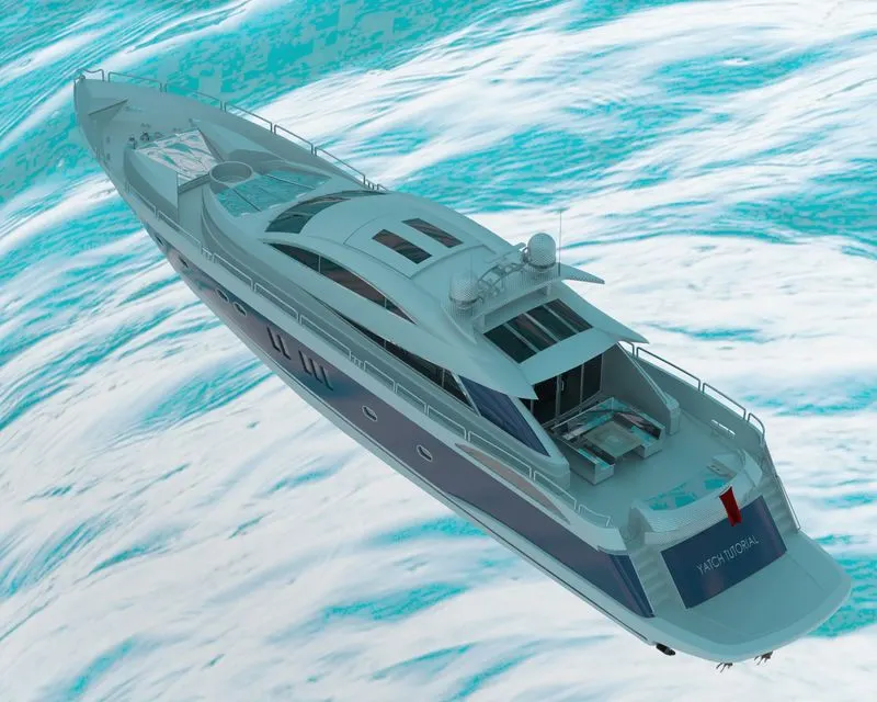
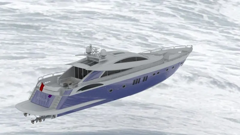
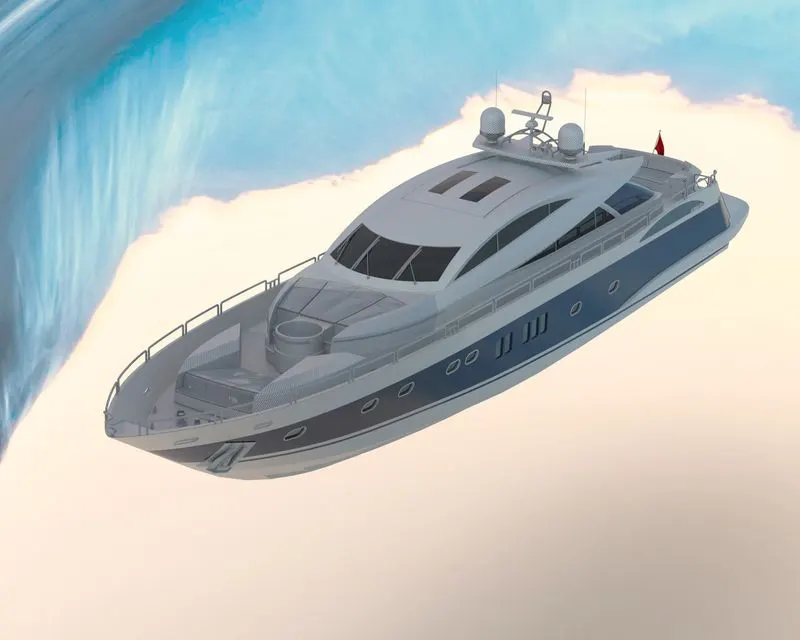
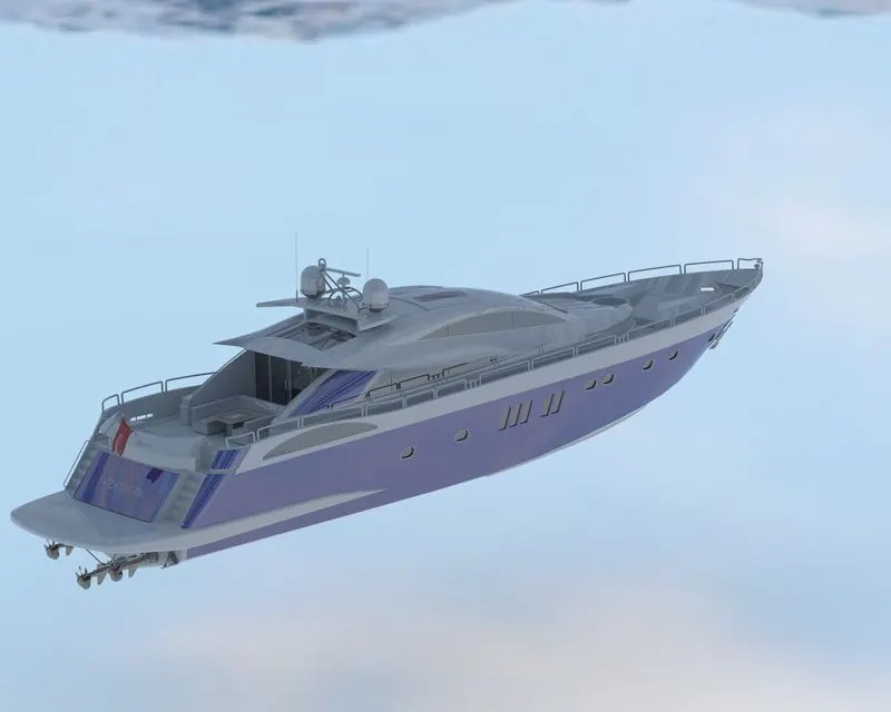
In rendering, the yacht was made to set up in such a way to look natural and unique. Decals were added to the body parts. Views and light directions were changed. Using solidworks visualize, the appearances, background scenes and camera views were changed and finally rendered.