Radar Mast & Final Assembly of Yacht
Title
Modelling Radar mast and assemble the Yacht using Solidworks
Objectives
- To model radar mast and assemble the yacht in SOLIDWORKS
- To perform a rendering in SOLIDWORKS VISUALIZE
Introduction
A yacht is a sailing or power vessel used for pleasure, cruising, or racing. Here we model a yacht in SOLIDWORKS. The different components of the yacht we deal with are propeller, radar, hull, garage door, front seat, middle seat, rear seat, super structure and radar mast. Here we took sun seeker predator model yacht for reference.
Design methodology
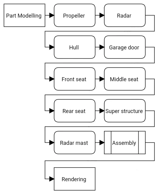
Primarily we draw the components of yacht and assemble it for rendering. It is represented as below.
Description
The SOLIDWORKS software is a mechanical design automation application that lets designers quickly sketch out ideas, experiment with features and dimensions, and produce models and detailed drawings. Parts are the basic building blocks in the SOLIDWORKS software. Assemblies contain parts or other assemblies, called subassemblies.
Let’s discuss what are the features and properties used in the entire model to design different parts:
SOLIDWORKS document windows have two panels. The left panel, or Manager Pane, contains:
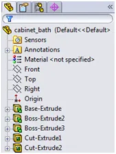
Feature Manager Design tree displays the structure of the part, assembly, or drawing. Select an item from the Feature Manager Design tree to edit the underlying sketch, edit the feature, and suppress and un suppress the feature or component, for example.
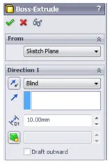
Property Manager: Provides settings for many functions such as sketches, fillet features, and assembly mates.
The basic modelling in Solidworks is represented below.
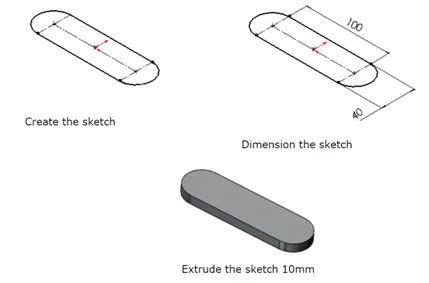
After we sketch the part, use the Extrude tool to create a 3D base feature. The sketch is extruded to the required thickness on sketch plane.
The Cut-Extrude tool is similar to an extrude feature, except that it removes material from the model instead of adding material.
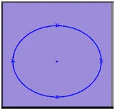
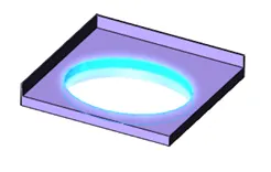
A loft creates a feature by making transitions between two or more sketch profiles. When we create a loft, the sketch profiles must reside on different planes (or planar faces).
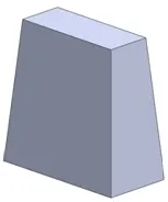
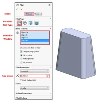
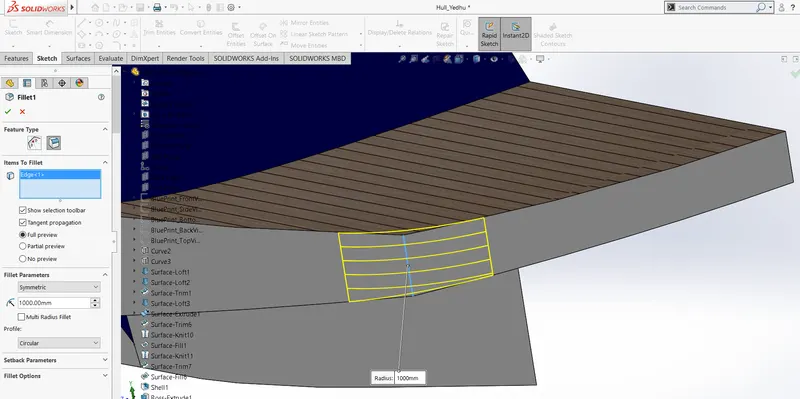
We round off sharp edges by adding fillet features to the model. When we create a fillet, we set the radius to determine the smoothness of the edges. Fillets are applied features, not sketch features. This means that fillets do not require creating a sketch. Instead, we select the edges of an existing feature, set the fillet radius, and create the fillet. As we increase the radius, the edges or faces become rounder.
We create a sketch with the Line and Spline tools. In some cases, we can add an axis of revolution with the Centreline tool. A centreline creates an axis that is construction geometry; it is not built into the feature. We then use the Revolve tool to rotate the sketch and create a solid feature.
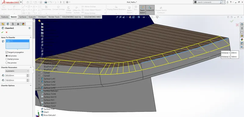
The Chamfer tool creates bevelled faces. A chamfer, like a fillet, is an applied feature, and does not require making a sketch to create the feature.
The sketch uses a mid-plane extrusion. Instead of extruding the sketch in one direction, you extrude the sketch equally in both directions perpendicular to the sketch.
To cut the model at the same angle on the opposite side, we use the Mirror tool to mirror the original cut about the plane of symmetry plane.
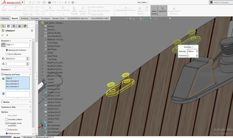
Linear Pattern tool copy the original tab a specified number of times. The linear pattern creates multiple instances of a selected feature along a linear path. When we make a linear pattern, we specify the number of instances and the distance between each tab.
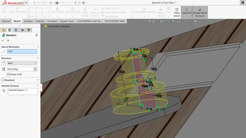
Revolved Boss Feature: Creates material by revolving a sketch around an axis. Remember, once geometry has been created in your model, any flat face can be used as a sketching surface. It is very important to draw an axis in the sketch which needs to be revolved.
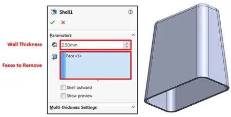
Shell: Solidworks shell tool is mainly used for shelling process, in which the material removed from the inner body of model by keeping small thickness and results a hollow model. Using this tool, you can make either completely closed hollowed model or one face opened type.
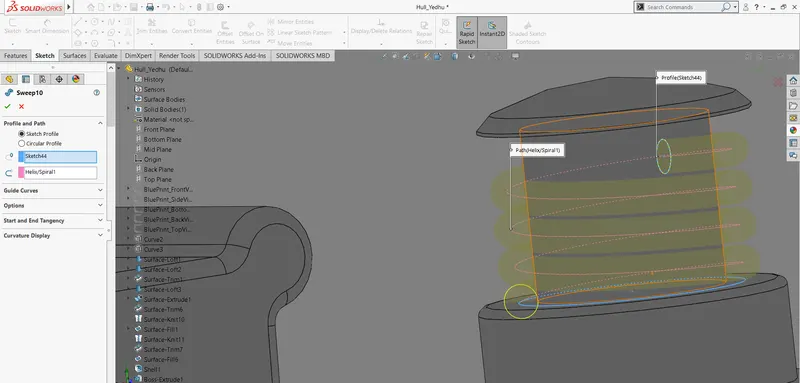
Sweep Boss / Sweep Cut: Sweep creates a base, boss, cut, or surface by moving a profile (section) along a path, according to these rules: The profile must be closed for a base or boss sweep feature; the profile may be open or closed for a surface sweep feature.
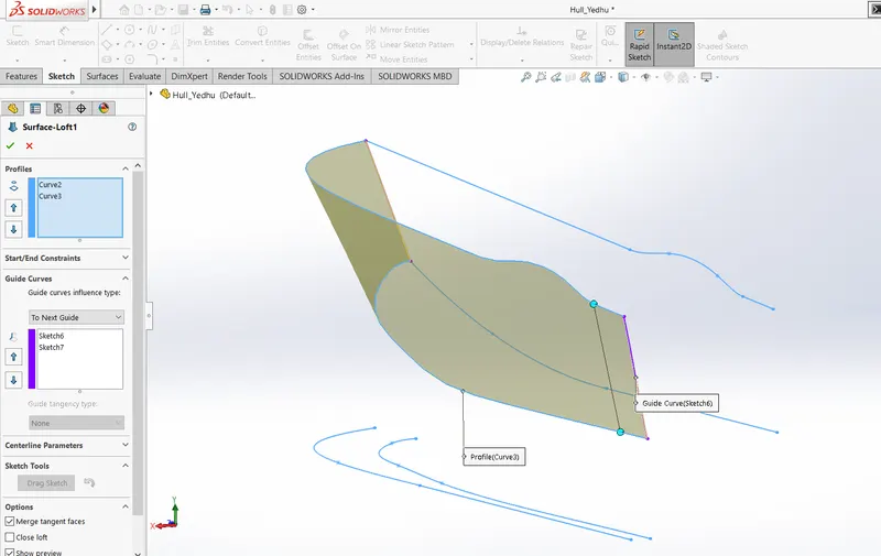
Surface Loft: The loft feature is an important tool for (surface) modelling in Solidworks. The loft feature creates a shape by making transitions between multiple profiles and guide curves. This tool is very valuable for modelling complex surfaces. You can do some cool stuff when you use this feature properly.
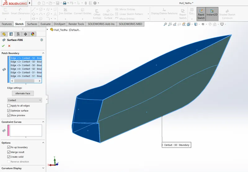
Surface Fill: Creates a surface to fill between the selected edges of the object. It is represented below.
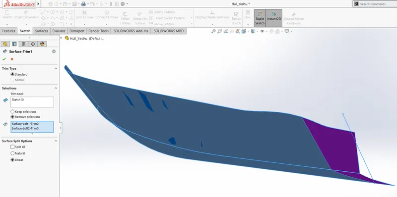
Surface Trim: Help us to remove unanted portion of the parts.
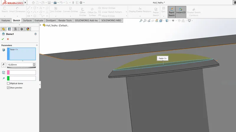
Dome: Creates a dome structure in selected surface. A representation is given below.
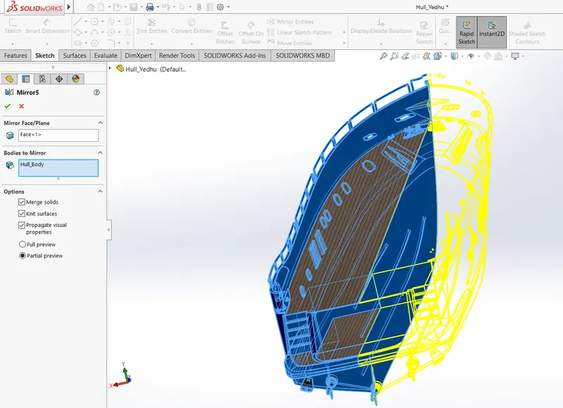
Mirror: Creates a copy of a feature, (or multiple features), mirrored about a face or a plane. You can select the feature, or you can select the faces that comprise the feature. Bodies to Mirror: Select a body in a single model or multi body part to create a mirror entity. Multi body parts: Apply features to one or more multi body parts by selecting Geometry Pattern and using Feature Scope to choose which bodies should include the feature.
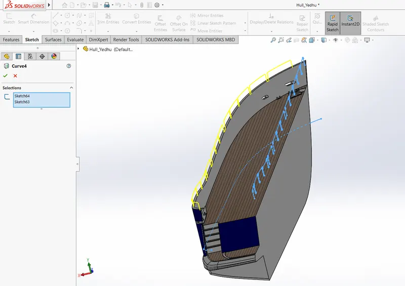
Projected Curve: You can project a sketched curve onto a model face to create a 3D curve. You can also create a 3D curve that represents the intersection of two extruded surfaces generated by creating sketches on two intersecting planes. You can create multiple closed or open-contour projected curves from a single sketch. You can also use 3D sketches as input for the Projected Curve tool. Note: the Projected Curve tool does not support projections of intersecting curves.
Mate: Mates create geometric relationships between assembly components. As you add mates, you define the allowable directions of linear or rotational motion of the components. You can move a component within its degrees of freedom, visualizing the assembly's behaviour.
Some examples include:
- A coincident mate forces two planar faces to become coplanar. The faces can move along one another but cannot be pulled apart.
- A concentric mate forces two cylindrical faces to become concentric. The faces can move along the common axis but cannot be moved away from this axis.
Mates are solved together as a system. The order in which you add mates does not matter; all mates are solved at the same time. You can suppress mates just as you can suppress features.
Now as we have completed discussion of how the features work under solid works let us see the application of the features in the yacht that we have built. We are going to discuss part by part as shown in the flowchart.
Propeller
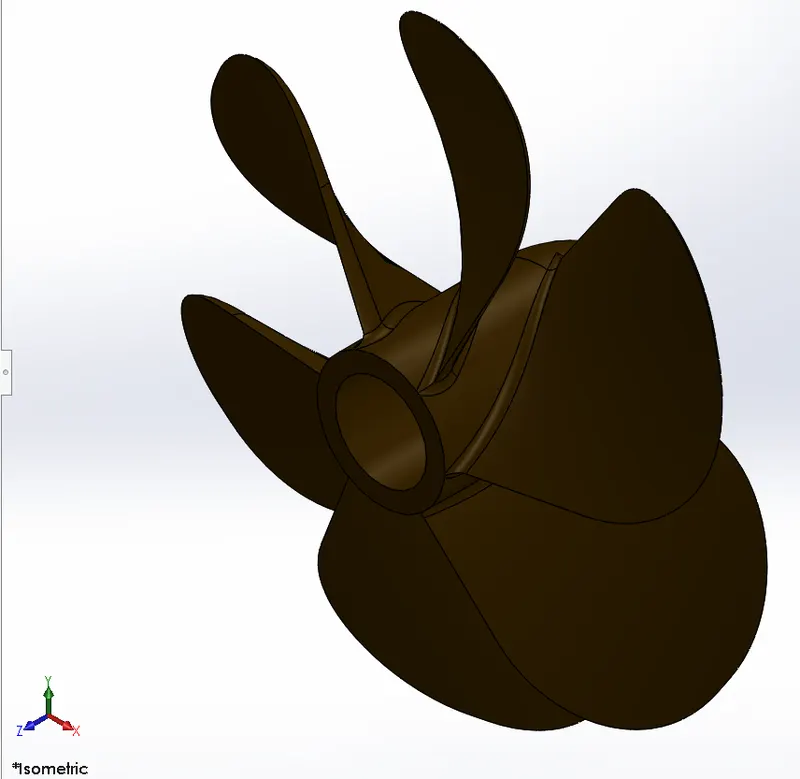
Propeller is a single body were a sketch was revolved to make the centre portion and a loft as created for the leaf. Cut extrude was given at canter for mounting propeller on shat and fillets were applied. Circular pattern used to complete the model and appearance colour was given.
Radar
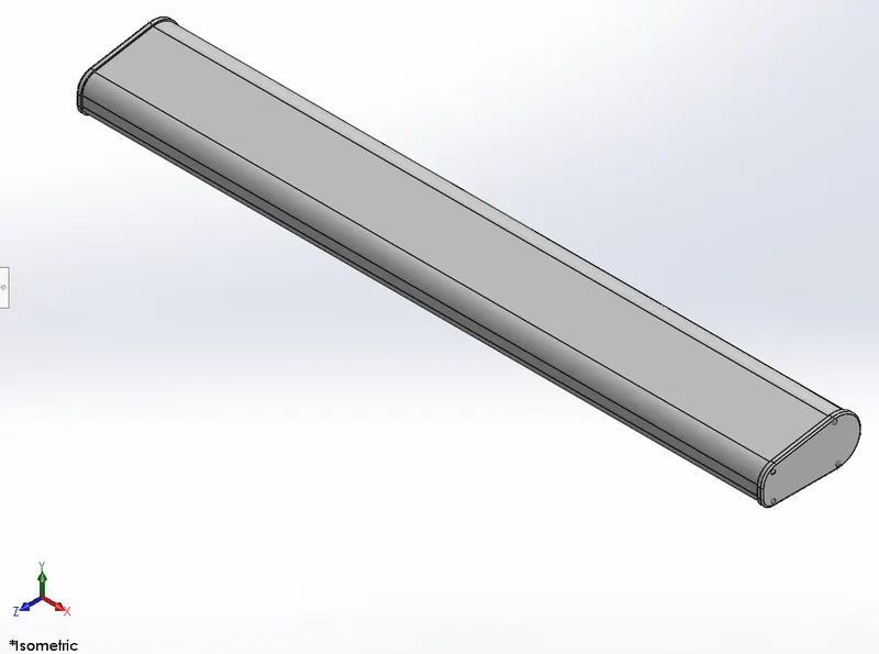
Radar is a single extrude were fillets were given to the edges. At end face small extrudes were done to resemble nuts and split line used to add text to the body.
Hull
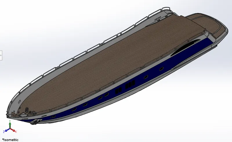
Hull is the main body of the yacht and it takes so many commands to make it. Initially the bottom parts were made by surface extrudes and it was knitted together.
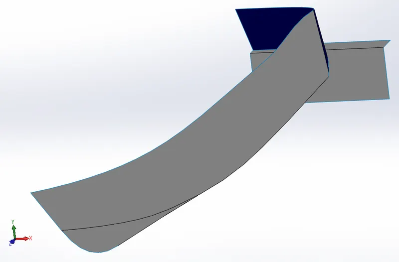
Surfaces were made by projected curves. Then the created surfaces were filled by surface fill command and shell command used to make the hull basic part.
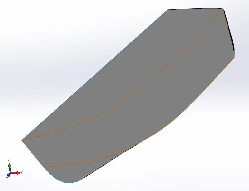
Again boss extrude were applied and fillets were applied for the further structure. Windows were created by cut extrude and window frames were made by sweep command. For the details, we add anchor and its rope to the structure. Rope was made using sweep command and helix spiral commands. Railing was also made by creating a railing reference by projected curve and proceeding by a sweep.
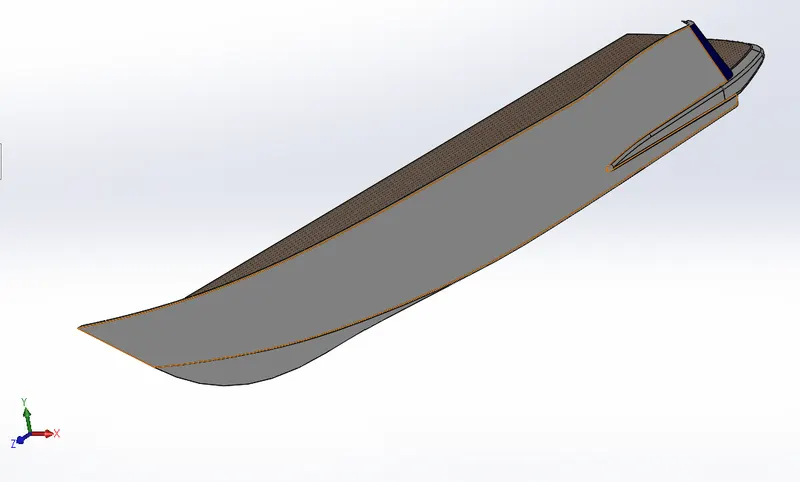
Same commands were used add more details like garage. For garage a cut extrude was done and the removed portion was saved externally to create garage door. A deck surface was also created for the future reference and to help in assembly. Pat as then finished by mirroring it completely and adding appearance colours.
Gauge Door
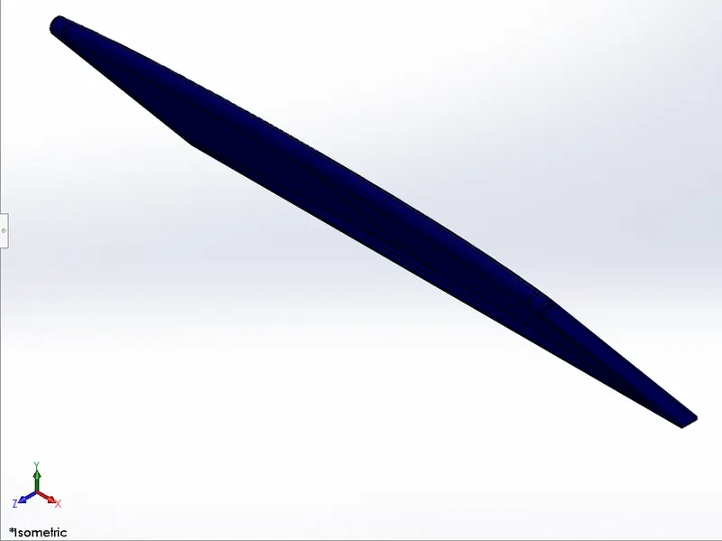
It is a part that we saved from hull and it is modified by cutting and giving fillets.
Front seat
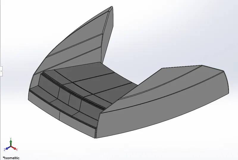
Front seat is developed by inserting the deck surface from hull. We create new sketch on that surface and performs surface sweep, surface fill, extrude and mirroring commands to obtain the desired look. To add more details we use fillets and dome commands. Every body is knitted and appearance colours were given.
Middle seat
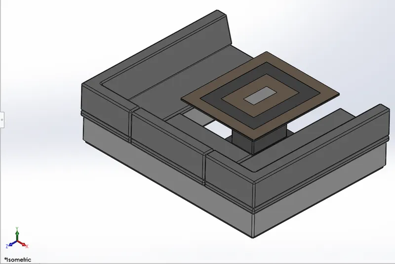
This part is also made similar as front seat. Deck surface is used as reference and extrudes were used to make the seats.
Rear Seat
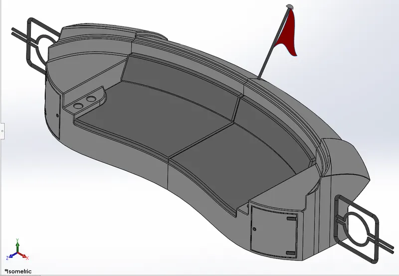
Rear seat is created by using deck surface reference. Extrude and extrude cuts are mainly used for the creation. Surface seep and surface offset commands were used for the basic body. Surfaces were extended and trimmed accordingly. Then they were knitted and details were added.
Super Structure
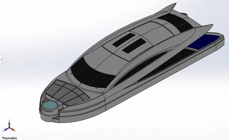
Super structure is also created on the deck surface reference. Initially complex geometries were formed by projected curve and surfaces were created. Those surfaces were filled and extended. Then they got trimmed accordingly. Surfaces were knitted and details were added.
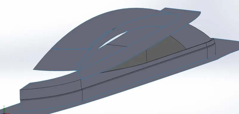
After forming solid bodies extruded cut were added to form windows. Extra details like Jacuzzi was added by extrude and railings were added by sweep. On the upper side of the part, a surface was created as reference for radar mast.
Radar mast
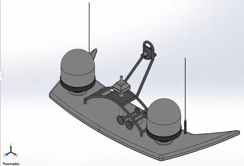
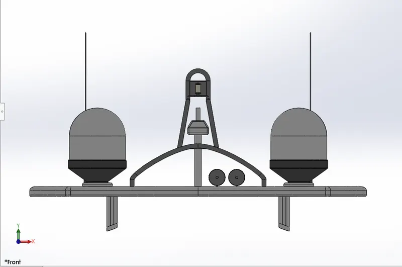
Initially, radar mast reference surface was inserted from superstructure. Sketches were made on that and extrude commands were performed. Revolve command was used to form dome like structure. Sweep was done for the railing structure. All the other details added and appearance was given.
Assembly
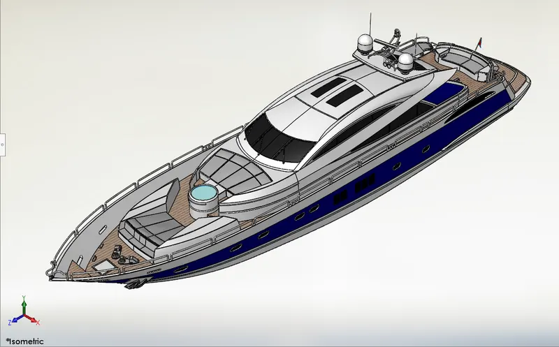
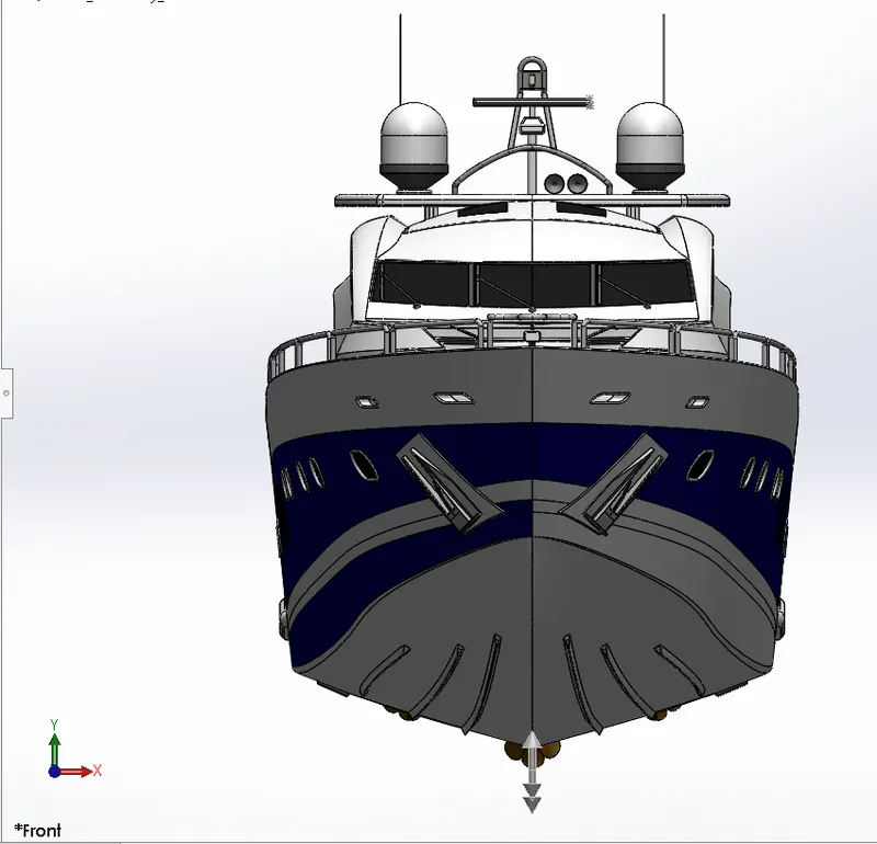
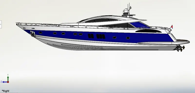
After opening an assembly file, we insert all the part files in to it. Hull, super structure, front seat, middle seat and radar mast will mate automatically because we created reference surfaces and all the parts were created on them. Additional mates were applied for radar, rear seat, garage door and propeller. Rear seat were mated by coinciding the middle plane of seat to middle plane of hull. Then a distance mate was given to two points so that seat will fix perfectly. Garage door was also fixed by coinciding right plane of door to middle plane of hull. Concentric mate was added between reference shafts. Radar and propellers were fixed using a concentric mate and coinciding two faces.
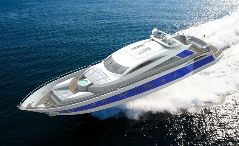
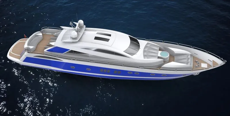
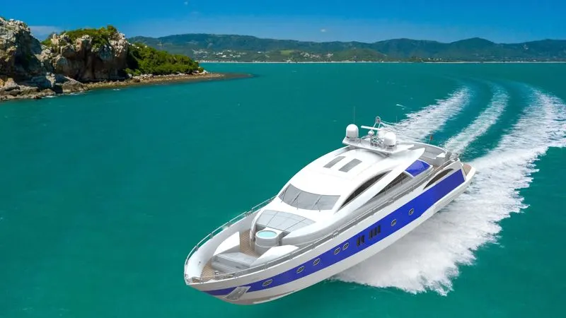
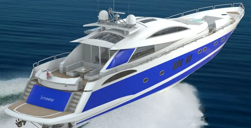
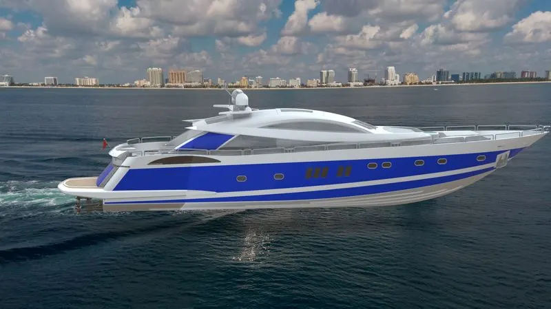
Rendering: The final step of the boat to make it look realistic is rendering. Here we try to make it look as realistic as it was possible we started off with checking the appearance added on all the parts. Now we try to make it more realistic by giving it a camera view setting the desired lights and the focal distance creating the angle of the view and saving the camera angle which gave a realistic view to the yacht. Now we take our assembly file into solid works visualize where we start making the product more and more realistic with adding the background changing the and adjusting the brightness, shadow density and gamma levels according to the different requirements of the different backgrounds changing the color of the model and checking what suits the best with which background until we get the desired and astonishing product ready.
Conclusion
Modelling and rendering of the yacht was completed.
Reference
[1] https://hawkridgesys.com/blog/features-basics-in-solidworks