Radar Mast & Final Assembly of Yacht
Radar Mast
Report
TITLE: Modelling, Assembly and Photorealistic Rendering of Sunseeker Predator Yatch
Objective:
- To create the 3D model of a Sunseeker Predator Yatch using SolidWorks 2020
- To Create the required parts for the Sunseeker Predator Yatch
- To build the assembly with right configuration
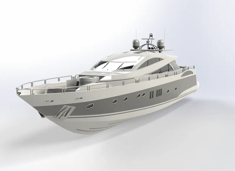
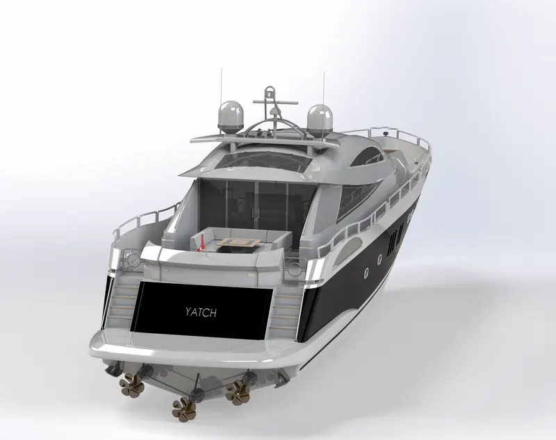
- To create the photorealistic rendering of a Sunseeker Predator Yatch
Introduction
A yacht is a sailing or power vessel used for pleasure, cruising, or racing. There is no standard definition, so the term applies to such vessels that have a cabin with amenities that accommodate overnight use.
Solidworks:
SolidWorks is a solid modelling computer-aided design and computer-aided engineering computer program published by Dassault Systems
This project consists of sketching, features, part modelling of an American chopper model. Added lights and cameras using Photoview 360 add in. Solidworks Visualize is used to add environments and have a quality rendering.
Tool Description:
Sketch:
- Line – It is a tool to draw a line using a start and end point. There are line, centreline, midpoint and construction lines
- Circle- It is a tool to draw a circle using centre point and required end point
- Spline- It is a tool to draw irregular shapes using fit points
- Rectangle—It is a tool used to draw 4 sides. Centre, corner and 3 sided rectangles are used
- Arc- It is a tool used to draw three-pointed arc on basis of position points
- Slot- It is used to create slots with straight and centre point slots
- Ellipse—It is a tool to create an oval shape using 2 snaps
- Trim entities—It is used to trim the unwanted sketches. Free form trim is used
- Convert entities—It is used to convert the required geometries on the sketch plane.
- Offset entities—It is used to offset the required sketches
- Extend- It is used to extend the entities to a required selection
- Mirror- It is used to duplicate the required geometry by planes, lines or axis as reference to mirror about.
- Pattern: Linear Pattern: - Its is used to create Linear patterns as copies. It requires direction of pattern, number of copies and distance between the copies.
Features:
- Sketch Plane- It is the plane where the sketch is developed
- Extruded Boss/Base- It is used to create solid from the geometry in one or both directions with different contours
- Revolved Boss/Base- It is used to create solid along the axis in different directions with contours
- Extruded Cut—It is used to remove material in a linear manner
- Fillet- It is used to create rounded face internally or externally.
- Chamfer- It is used to create smooth edges for a model
- Pattern: -Linear Pattern: - It is used to create multiple copies in linear manner by inputting direction, number of copies and distance between copies.
- Mirror- It is used to create copies by referring a line or a plane to mirror about.
- Shell- It is used to create a hollow surface leaving behind a thin layer feature
- Reference- It consists of plane, axis, curves etc to create a reference which helps to create different geometry.
- Dome- It is used to create one or more dimes for a model.
Surface:
- Sweep surface- It used to generate surface of a sketch along a path
- Extrude Surface – It is used to used to extrude the surface
- Loft surface – It generates surface using multiple sketches of different geometry along specified path
- Projected curve- It is used to create a 3D curve using multiple 2D curves.
- Knit surface- It is used to combine multiple surfaces
- Trim surface- It is used to intersecting surfaces
- Fill Surface- It fills the patch within the defined edges
- Extend surface- It extends the one or more edges
Parts of American Chopper:
- Propeller
- Radar
- Hull
- Garage Door
- Front Seat
- Middle Seat
- Rear Seat
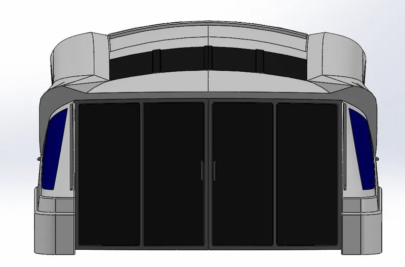
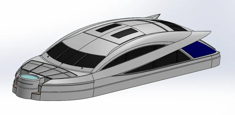
- Superstructure
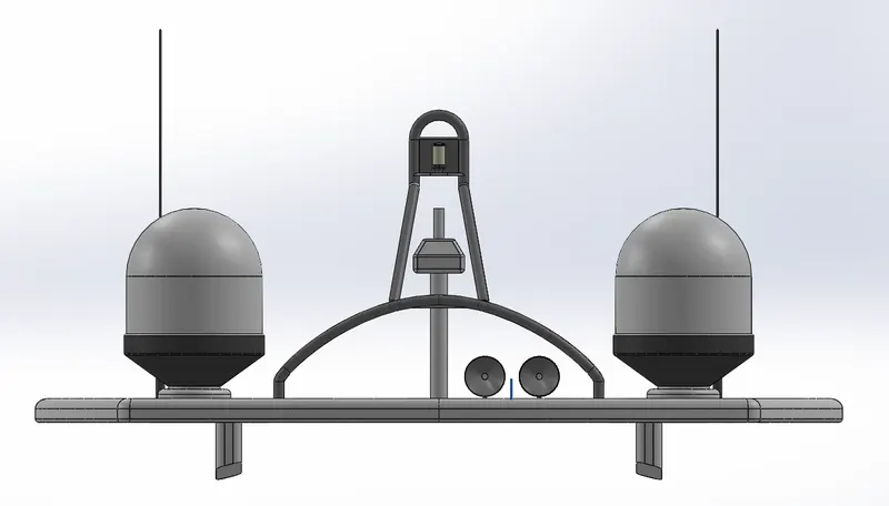
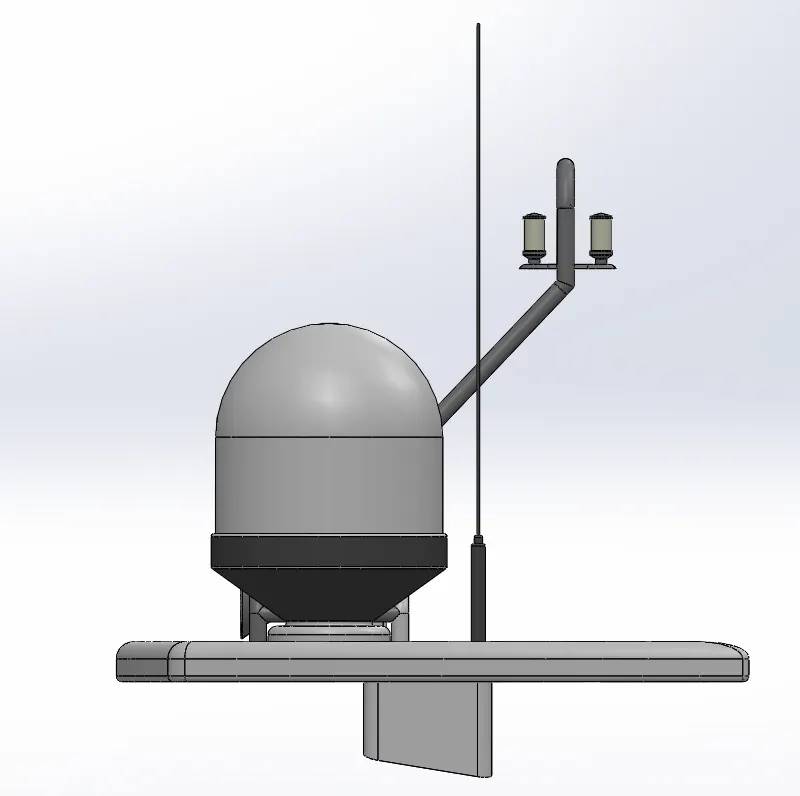
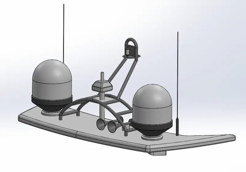
- Radar Mast
Description:
- Blueprints:
Process:
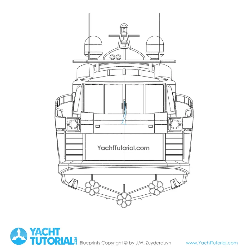
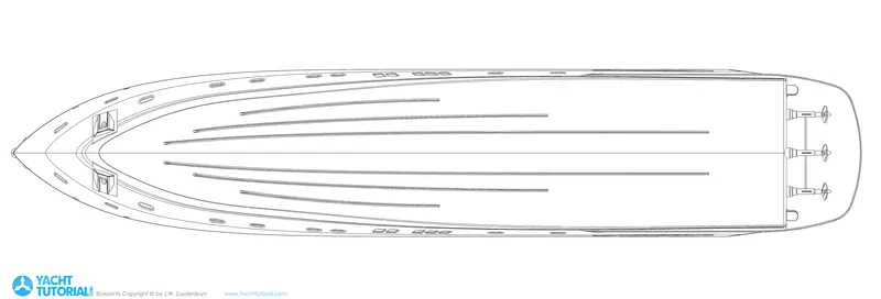
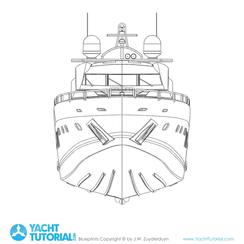
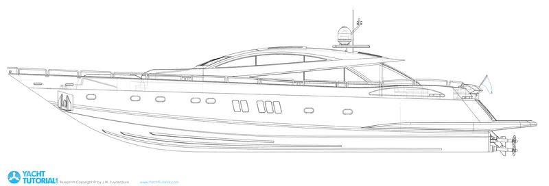
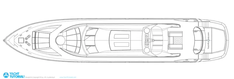
Blue prints are the most essential for a 3D model to be developed. The blueprints for this project are insert by this Insert> Sketch Tools> Sketch Pictures. The blueprints are imported and dimensions are given to their coordinated and placed at the right spot. The blueprints are named after the view for the ease of modelling. Totally 5 blueprints Top, Bottom, Front, Rear and Side view.
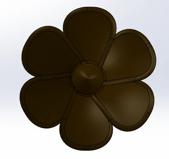
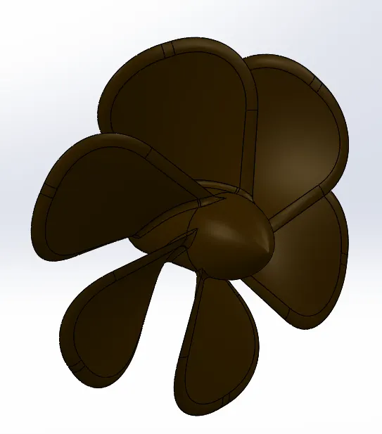
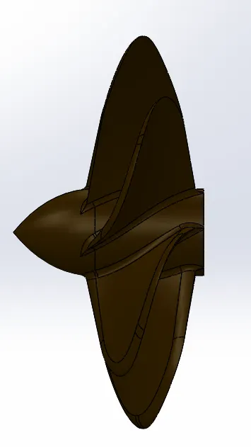
- Propeller
Tools used:
- Sketch
- Extrude
- Extrude cut
- Revolve
- Circular pattern
- Appearance
Process: The 2D sketch is converted to 3D by using revolve with a hub for the propeller. The blades are created using loft as per the dimensions and patterned using circular pattern around the hub. Extrude cut is used to remove materials in the hub. Fillet is used to remove the sharp edges.
- Radar
Tools Used:
- Sketch
- Convert Entities
- Offset Entities
- Extrude Boss/Base
- Cut Extrude
- Sketch Driven Pattern
- Split line
- Fillet
- Appearance
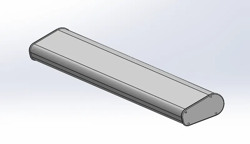
Process:
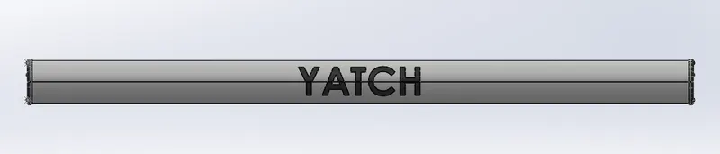
A Sketch is extruded with fully defined sketch with appropriate dimensions as per the blueprint. Sketch driven pattern is created to form the patterns of bolt. Text tool and split line tool is used for the text to be labelled. Fillet is used too remove the sharp edges and Appearance is applied.
- Hull
Tools Used:
- Sketch
- Extrude
- Cut extrude
- Shell
- Surface Extrude
- Surface revolve
- Surface fill
- Surface loft
- Surface sweep
- Knit surface
- Surface trim
- Extend surface
- Linear Pattern
- Mirror
- Appearance
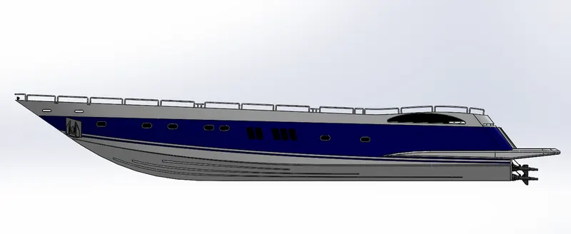
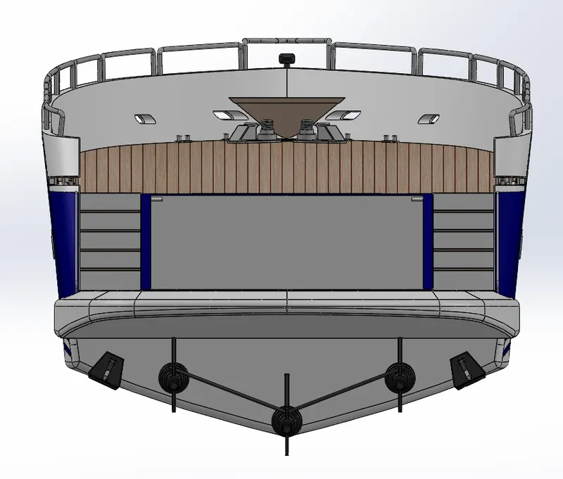
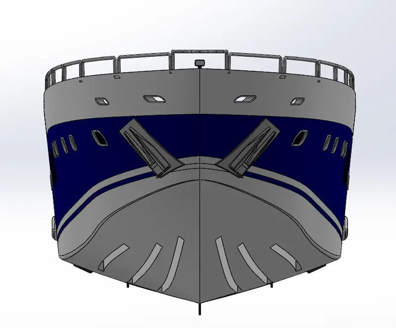
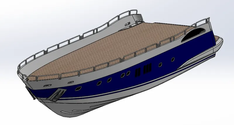
Process: The hull model is done suing surface commands and turned into a solid. Using the blueprints and dimensions surface are created suing splines, planes and lines. Projected curve was used to get the 3D view for the surface to be modelled. Trimming operations were done on edges so to not leave any gaps and to be fully defined. Fillets are used to remove the sharp edges.
- Garage Door
Tools Used:
- Sketch
- Extrude
- Extrude cut
- Fillet
- Shell
- Mirror
- Appearance
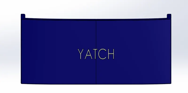
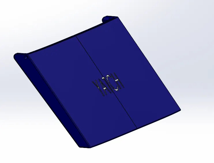
Process: The body which is saved for reference while modelling hull is used to model garage door. Extrude cutis used to remove the material to get the exact shape. Fillet is used to remove the sharp edges.
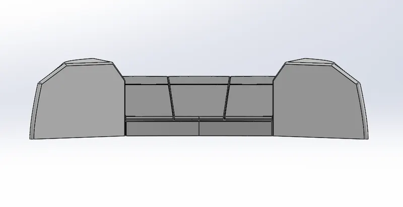
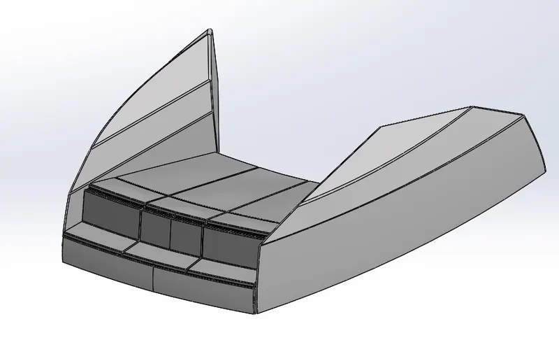
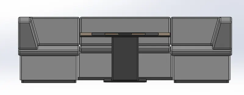
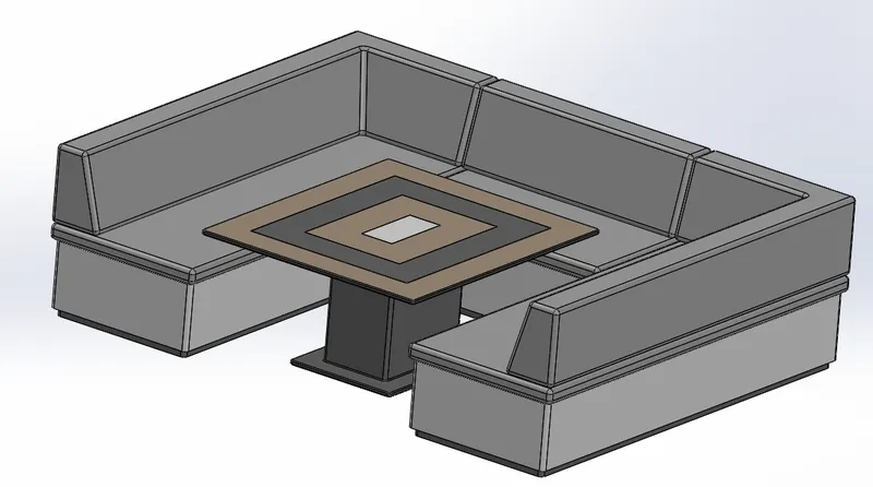
- Front Seat, Middle Seat and Rear Seat
Tools used for Front Seat:
- Sketch
- Extrude
- Extrude cut
- Swept surface
- Surface loft
- Knit Surface
- Fillet
- Chamfer
- Mirror
- Dome
- Appearance
Tools used for Middle Seat:
- Sketch
- Extrude
- Extrude cut
- Fillet
- Knit surface
- Chamfer
- Mirror
- Appearance
Tools used for Rear Seat:
- Sketch
- Extrude
- Extrude cut
- Surface loft
- Surface sweep
- Knit surface
- Trim surface
- Ruled surface
- Fillet
- Chamfer
- Mirror
- Appearance
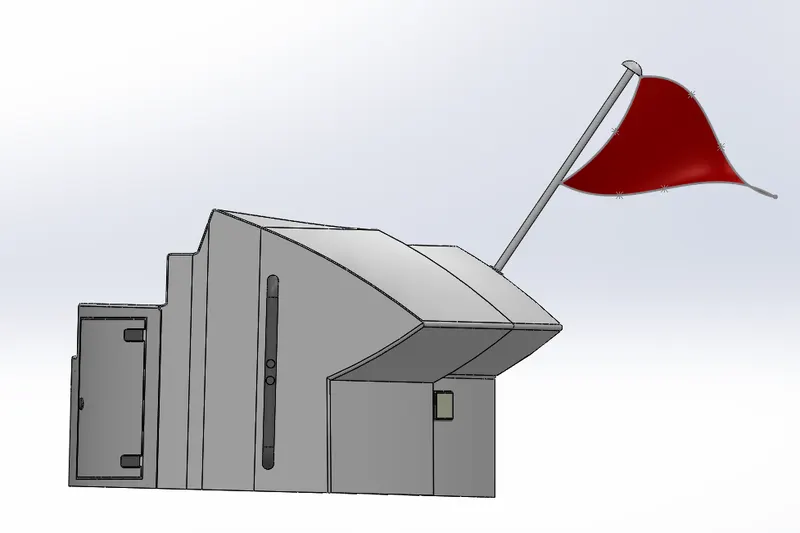
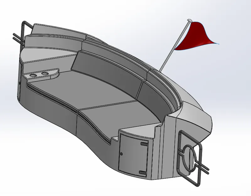
Process: Front, middle and rear seats are developed from the deck surface inserted from the hull model which acts as the reference for the models to be created. Surface commands are used to create the models and converted into solid. Model should be ensured that the sketch is fully defined and it is mirrored.
- Superstructure
Tools used:
- Sketch
- Offset entities
- Extrude
- Extrude cut
- Surface loft
- Surface sweep
- Surface extrude
- Extend surface
- Knit surface
- Surface fill
- Projected curve
- Fillet
- Chamfer
- Mirror
- Appearance
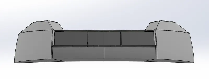
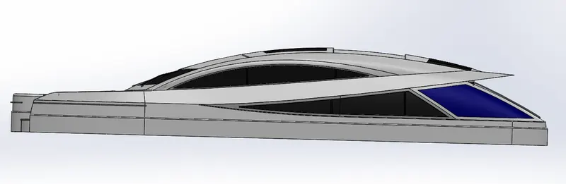
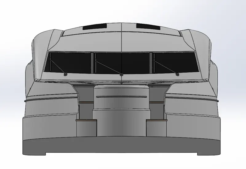
Process: The model s developed on the deck surface which is inserted from the hull model. The model used surface commands and later turned into a solid and mirrored. It is ensured the surface are knitted without any gaps and full defined.
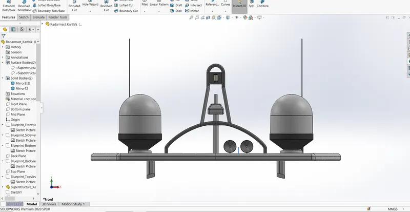
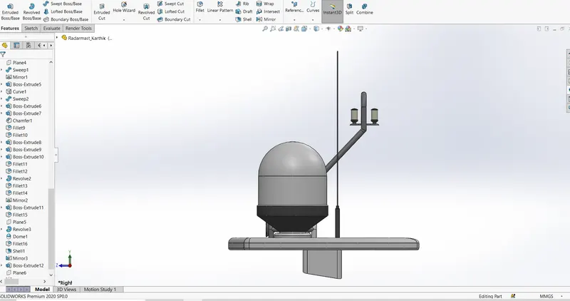
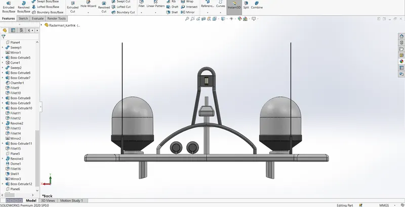
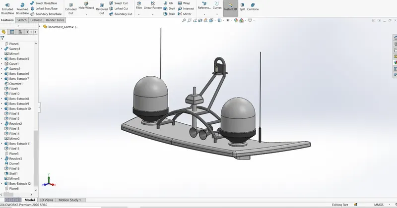
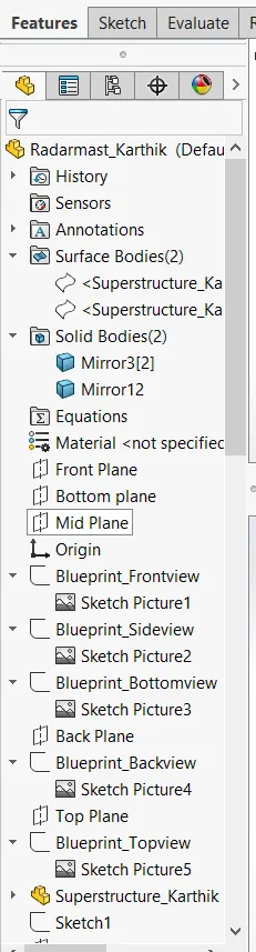
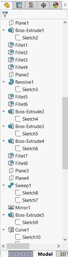
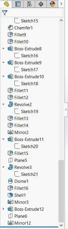
- Radar Mast
Tools used:
- Sketch
- Extrude
- Revolve
- Dome
- Shell
- Fillet
- Mirror
- Appearance
Process: The model is created on the surface od superstructure which is taken as the reference. Sweep, loft, projected curve and extrude are used. Finally, the model is mirrored.
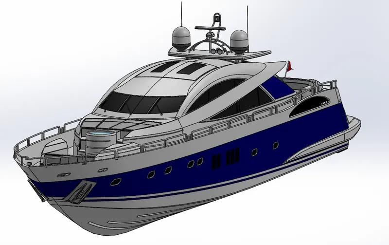
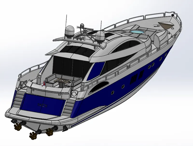
Assembly
Process of Assembly:
- Hull is inserted to the assembly environment.
- Superstructure is inserted to the assembly.
- Front seat and middle seat are inserted to the assembly.
- Radar Mast is inserted to the assembly.
The above parts are automatically locating their position.
- Garage Door is inserted to the assembly, mid plane of hull and right plane of garage door are given coincident relation. Concentric relation is given to the pin and hole of door.
- Rear Seat is inserted to the assembly, deck surface of hull and bottom surface of rear seat is given coincident relation. Centre point of deck surface and centre point of rear seat are given distance relation of 50mm.
- Radar is inserted and hole of radar and radar mast is given concentric relation. Coincident relation is given to fully define.
- Propeller is inserted and given coincident relation for the hub and hull. Coincident relation is given to the hub to fully define.
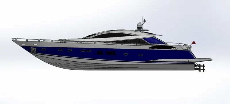
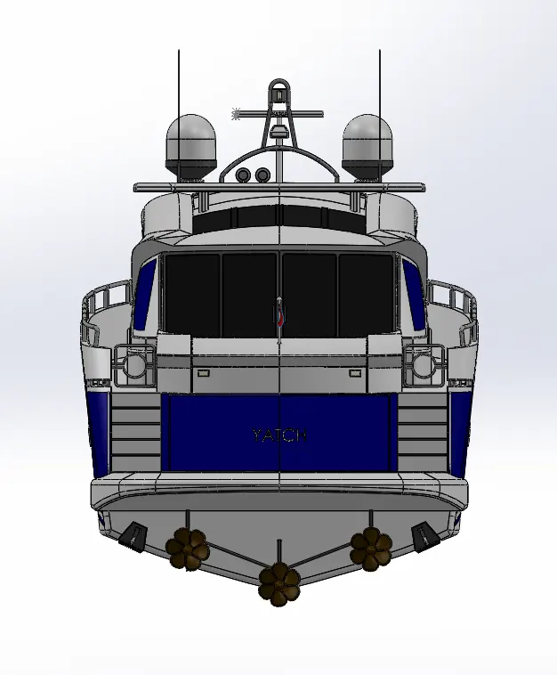
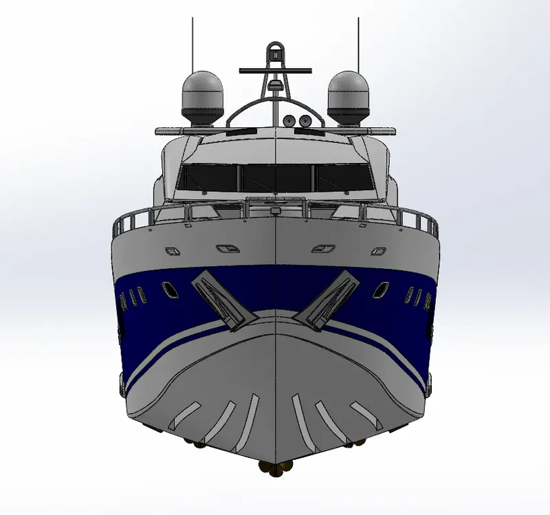
Rendering
Conclusion:
- This Project got me vast knowledge about various tools of SolidWorks, designing methods, designing approach and important techniques to ace the 3D modelling.
- Rendering techniques which really helpful to have a complete package of 3D modelling from start to end.