Radar Mast & Final Assembly of Yacht
RADAR MAST
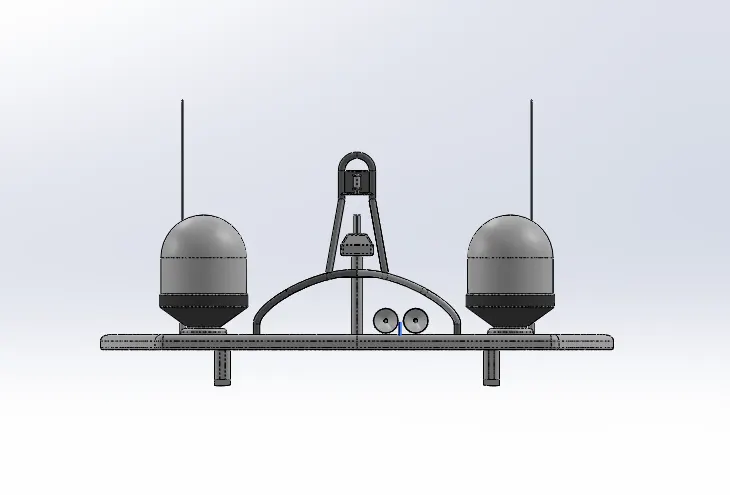
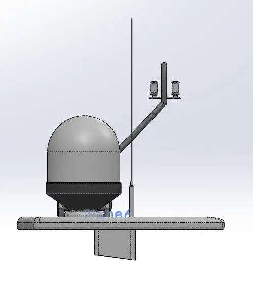
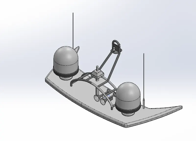
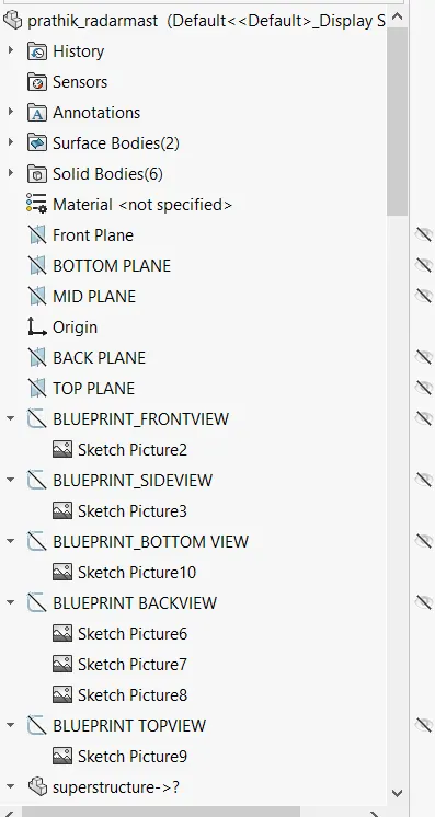
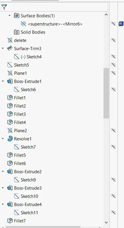
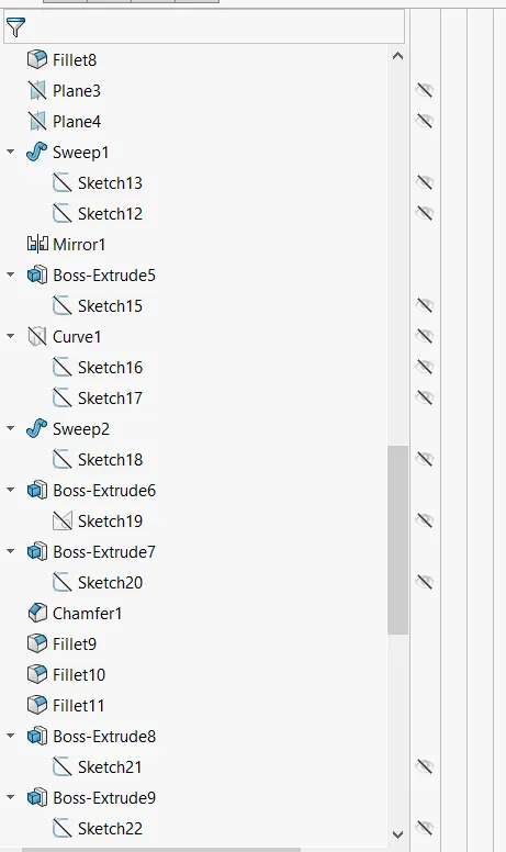
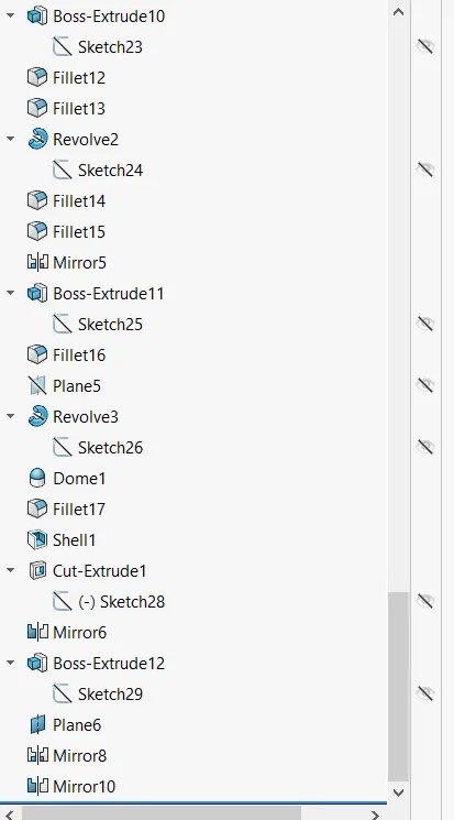
feature tree of radar mast
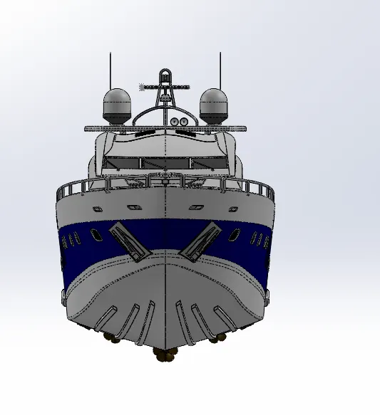
ASSEMBLY:
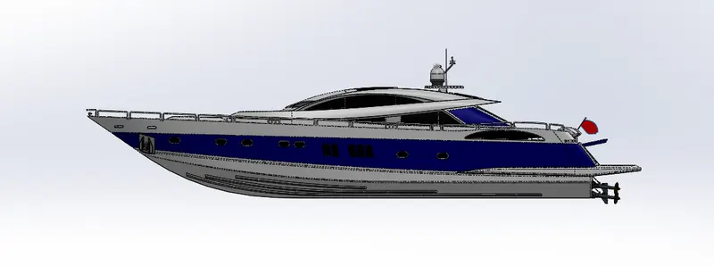
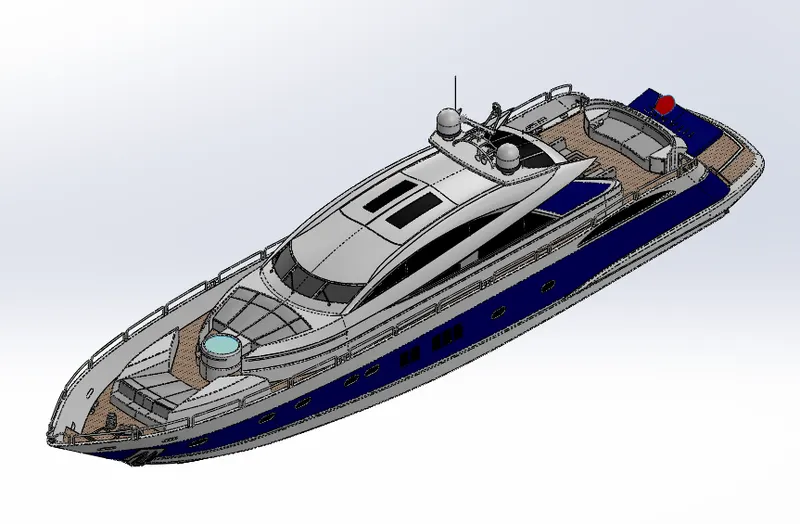
FEATURE TREE:
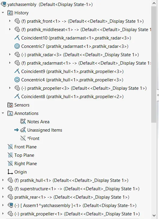
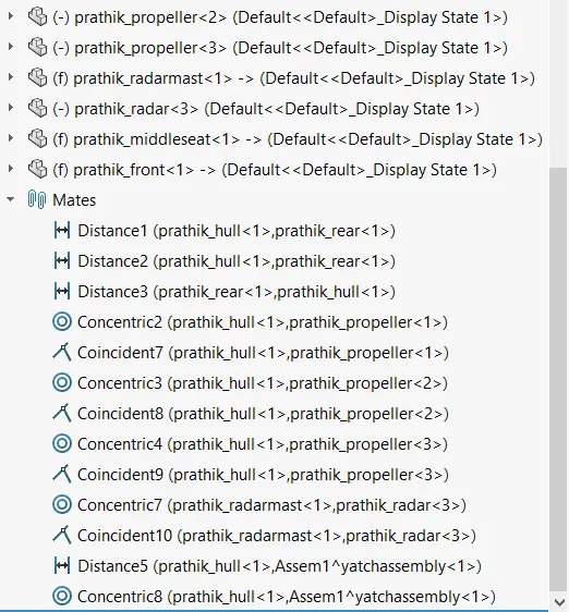
REPORT:
MODELLING OF YATCH IN SOLIDWORKS
SOLIDWORKS INTRODUCTION:
Mechatronics, the combination of robotics, electronics, computer, and control systems, has resulted in a variety of amazing products from smart phones to self-driving cars. In order to create those products, they need to be digitally modeled and developed. SOLIDWORKS, a solid modeling computer-aided design and computer-aided engineering program, is one of the most popular software options for Mechatronics engineers. Solid Works is computer-aided design software owned by Dassault Systèmes. It uses the principle of parametric design and generates three kinds of interconnected files: the part, the assembly, and the drawing. Therefore, any modification to one of these three files will be reflected in the other two.
Solid works helps you perform 2D and 3D modeling, and this CAD software is known for its ease-of-use and intuitiveness.
Solid Works software enables you to:
- design very precise 3D objects
- develop products
- double-check your file's design
- maintain a library of your 3D files
- create 2D drawings
- create images and animations of your 3D objects
- estimate the manufacturing cost of your 3D objects
Softwares required: SOLID WORKS, Photo view 360
SOLIDWORKS 2016 System Requirements
Operating System
Supported Systems:
- Windows 10, 64-Bit
- Windows 8.1, 64-Bit
- Windows 8.0, 64-Bit
- Windows 7 SP1, 64-Bit
- Windows 7 SP1, 32-Bit
RAM
- 64 bit: 8 GB (min), or more – recommended for large assembly work and Simulation and also graphic card 1 GB (min).
Though these recommendations are a good starting point for spacing out a SOLIDWORKS machine, it is always a good idea to conduct your own hardware/software tests before purchasing any workstation, computer hardware, or video card for Solid Works.
Objective:
The main objective is
- To create all individual parts which are required for the solid modeling of American chopper
- Next is how to assemble all the parts of the American chopper
- Finally using photorealistic model and render it using Photoview 360 along with the application of Decals, lights and camera.
Design Process The design process usually involves the following steps:
- Identify the model requirements.
- Conceptualize the model based on the identified needs.
- Develop the model based on the concepts.
- Analyze the model.
- Prototype the model.
- Construct the model.
- Edit the model, if needed.
DESIGN PLAN/ DESIGN PROCEDURE:
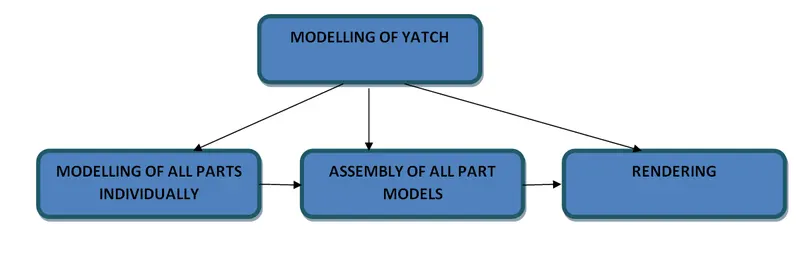
FEATURES OF SOLIDWORKS:
Sketch: A collection of lines and other 2D objects on a plane or face that forms the basis for a feature such as a base or a boss. Sketching is done using sketch entities such as splines, lines, rectangle, circles etc. The sketch is the basis for most 3D models. Creating a model usually begins with a sketch. From the sketch, you can create features. You can combine one or more features to make a part. Then, you can combine and mate the appropriate parts to create an assembly. From the parts or assemblies, you can then create drawings. A sketch is a 2D profile or cross section. To create a 2D sketch, you use a plane or a planar face. In addition to 2D sketches, you can also create 3D sketches that include a Z axis, as well as the X and Y axes. There are various ways of creating a sketch.
Loft: Loft creates a feature by making transitions between profiles. A loft can be a base, boss, cut, or surface.
You create a loft using two or more profiles. Only the first, last, or first and last profiles can be points. All sketch entities, including guide curves and profiles, can be contained in a single 3D sketch.
Extrude Boss: Extruded Boss/Base feature, this is one of the most common and universal features used within the 3D modeling world. This is a handy feature for creating 3D solid models within SolidWorks.
Using the modeled 2D sketch created, you are ready to turn the 2D sketch element into a 3D solid feature. The Extruded Boss/Base feature can be found on the features tab in the Command Manager.
Extrude cut: Extruded Cut is a handy feature to aid in material removal of a 3D model using 2D sketches. Using the Extruded Boss/Base model created in the Extruded Boss/Base, we will modify the 3D block to include a circle feature by removing material. The Extruded Cut feature can be found on the features tab in the Command Manager
Dome: A dome is a curved formation or structure. It is shaped like half of a sphere. Imagine cutting an orange in half, and placing it cut-side-down on a table. This is the shape of a dome, although most domes in nature are not perfectly rounded. elliptical dome is for cylindrical or conical models. An elliptical dome's shape is a half ellipsoid, with a height equal to one of the ellipsoid radii.
Fillet: Fillet/Round creates a rounded internal or external face on the part. You can fillet all edges of a face, selected sets of faces, selected edges, or edge loops by specifying distance.
Chamfer: A chamfer is the sloped or angled edges or corners of a part design. It is an antonym of the fillet. Instead of having a curved shape, a chamfer is straight and has a sharp angle. Chamfering is done mentioning either with distance distance or angle distance.
Split: Split feature is to create multiple parts from an existing part. You can create separate part files, and form an assembly from the new parts. You can split one or more solid or surface bodies. To split a surface, the Trimming Surface must extend past the boundaries of the surface to split.
Patterns: this feature is used to pattern the entities in any specified direction. There are different types and ways there can be used based on our requirement.
- Curve Driven Patterns
The Curve Driven Pattern tool allows you to create patterns along a planar or 3D curve. To define the pattern, you can use any sketch segment, or the edge of a face (solid or surface), that lies along the plane. You can base your pattern on an open curve, or on a closed curve, such as a circle.
- Linear Patterns
Use linear patterns to create multiple instances of one or more features that you can space uniformly along one or two linear paths.
- Circular Patterns
Use circular patterns to create multiple instances of one or more features that you can space uniformly around an axis.
- Sketch Driven Patterns
Using sketch points within a sketch, you can specify a feature pattern. The seed feature propagates throughout the pattern to each point in the sketch. You can use sketch driven patterns for holes or other feature instances.
- Table Driven Patterns
Using X-Y coordinates, you can specify a feature pattern. Hole patterns using X-Y coordinates are a common application for table driven patterns. However, you can use other seed features, such as a boss, with table driven patterns. You can also save and load the X-Y coordinates of a feature pattern, and apply them to a new part.
Blocks: You can make, save, edit, and insert blocks for drawing items and sketch entities that you use often, such as standard notes, title blocks, label positions, and so on. You can attach blocks to geometry or to drawing views, and you can insert them into sheet formats.
Mirror: The ability to mirror can be found in part and assembly files, and allows you to mirror sketch entities, features, faces, bodies, and components. Mirroring is done when you want to get the same design wrt to a line or plane. Mirroring is best way to reduce time and avoid errors. Mirroring sketch entities can be done wrt to a line while mirroring features is done wrt plane. You can also mirror the components while in assembly wrt a reference plane.
Projected curve: it is a tool you are going to use to form 3D curves from two 2D curves from two different planes. But the two sketches should be orthogonal or perpendicular. They are 2 types based on usage we can use either sketch on face and sketch on sketch.
Reference geometry: Reference Geometry includes reference planes, axes, coordinate systems, and points. Make sure they are fully defined while created. While creating reference plane these are the various ways you can define it.
- Offset Distance
- Coincident with 3 vertices
- Coincident with a line and a vertex
- Angle
- Parallel
- Tangent and Parallel
- Tangent and Perpendicular
- Mid Plane
- Perpendicular at a Point
- Create a plane parallel to the screen
Appearances: An appearance defines the visual properties of a model, including color and texture. Appearances do not affect physical properties, which are defined by materials.
Mates: mates create a geometric relationship between the assembly components so that they are defined. As we define mates we define the allowable directions of linear and rotational motion of the components. We can also restrict and allow the motion within the assembly based on our convenience.
SURFACE MODELLING
Surface Modeling is the method of showing or presenting solid objects. The process requires you to convert between different 3D modeling types, such as converting the 3D object to show procedural surfaces, validate imperfections, and apply smoothness. While more complex than Wireframe Modeling, Surface Modeling is easier to achieve than Solid Modeling.
In a CAD environment it is possible to fully produce a model using only surface modeling - but most real-world applications require a combination with solid modeling technique as well. How a designer is able to interact and manipulate an object in a CAD system is the difference between solid and surface modeling.
Freeform surface, or freeform surfacing, is used in CAD and other computer graphics software to describe the skin of a 3D geometric element. Freeform surfaces do not have rigid radial dimensions, unlike regular surfaces such as planes, cylinders and conic surfaces. They are used to describe forms such as turbine blades, car bodies and boat hulls. Initially developed for the automotive and aerospace industries, freeform surfacing is now widely used in all engineering design disciplines from consumer goods products to ships
HOW MODELLING IS DEFINED?
When defining a form, an important factor is the continuity between surfaces - how smoothly they connect to one another.
One example of where surfacing excels is automotive body panels. Just blending two curved areas of the panel with different radii of curvature together, maintaining tangential continuity (meaning that the blended surface doesn't change direction suddenly, but smoothly) won't be enough. They need to have a continuous rate of curvature change between the two sections, or else their reflections will appear disconnected.
The continuity is defined using the terms
- G0 – position (touching)
- G1 – tangent (angle)
- G2 – curvature (radius)
- G3 – acceleration (rate of change of curvature)
SURFACE MODELING COMMANDS:
- Extrude surfaces: extrude sketch in one or 2 directions to create surface features.
- Swept surfaces: creates a sweep closed profile along an open or closed path to create a surface feature. It uses a tangent plane at the end of path so that path is normal to swept surface
- Trim surface: it trims the unwanted surface when one surface intersects with another surface
- Knit surface: it combines two or more surfaces into a single surface body.
- Ruled surface: inserts the ruled surfaces in an specified direction from edges either tangent or normal or tapered or perpendicular to given edge.
- Revolve surface: revolves a selected sketch surface around an axis to get it.
- Mirror surfaces: It is used to mirror surfaces about a plane.
- Extend surface: extends one or more selected edges on a surface based on end specified.
- Filled surfaces: patches a surfaces within a boundary defined by edges, sketches or curves.
YATCH:
A yacht is first defined either as a sailing yacht, motor yacht, or gulet yacht, and then as a sports or luxury yacht. A yacht is a craft used for pleasure and sport. The name comes from the Dutch word jaght, which translates as ‘hunter’, a fast, light sailing vessel used in the past by the nation’s navy to chase pirates and other ne’er do wells.
- Sailing Yacht: a yacht mainly propelled via wind and sails
- Motor Yacht: a yacht propelled via one or more motors
- Gulet Yacht: a hybrid yacht with both sails and motors
- Open Yacht, Cruiser, Cabin Cruiser, Express Cruiser: an otherwise uncategorized standard yacht for cruising and entertaining
- Luxury Yacht: a yacht that includes high-end finishes and features and the latest in modern performance technology. The term ‘luxury’ can precede any type of yacht, i.e. “luxury motor yacht”, “luxury sailing yacht”, etc.
- Sports Yacht: a yacht geared towards fishing, water sports, or cruising with a sleeker design and more powerful motor for faster cruising speeds. The term ‘sports’ can precede other types of yachts as well, i.e. “sports motor yacht”.
- Catamaran Yacht: a yacht with two hulls (pontoons) often made of fiberglass that can be used in shallow waters.
Yatch or Yacht consists of different part and all are assembly onto a fixed part model and final rendering is done.
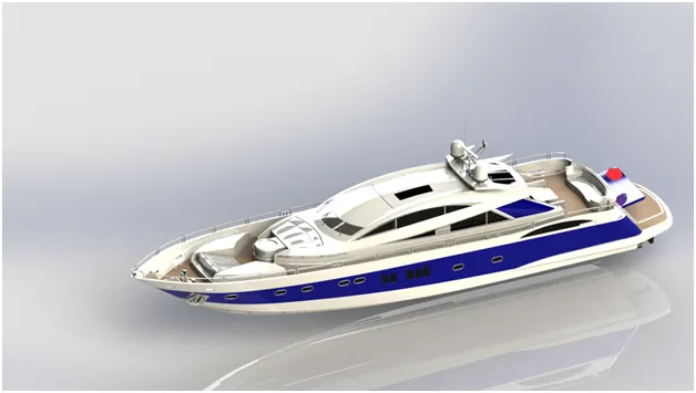
The following are the parts of Model
- Propellor
- Radar
- Hull
- Garage door
- Front seat
- Middle seat
- Rear Seats
- Superstructure
- Radarmast
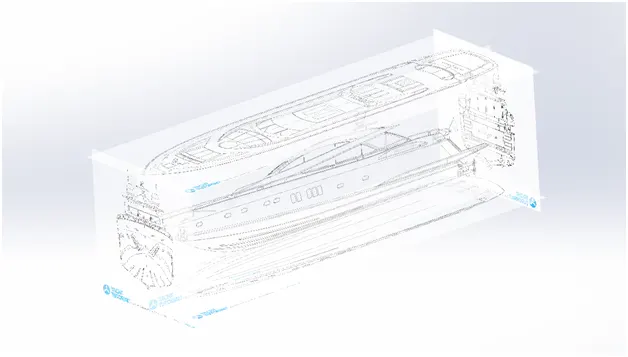
BLUEPRINT SETUP IN SOLIDWORKS
The first and foremost step in this project is to setup the blueprints in the solidworks and these blueprints are used as reference for the entire project development. The blueprints of yatch in all directions i,e front view, back view, top view and side view are taken and inserted accordingly .
To setup blueprints
First import the blueprints into solidworks part files using Tools >> Sketch tools >> sketch picture
PROPELLOR:
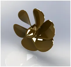
A propeller is a rotating fan-like structure which is used to propel the ship by using the power generated and transmitted by the main engine of the ship.
The transmitted power is converted from rotational motion to generate a thrust which imparts momentum to the water, resulting in a force that acts on the ship and pushes it forward.
A ship propels on the basis of Bernoulli’s principle and Newton’s third law. A pressure difference is created on the forward and aft side of the blade and water is accelerated behind the blades.
The thrust from the propeller is transmitted to move the ship through a transmission system which consists of a rotational motion generated by the main engine crankshaft, intermediate shaft and its bearings, stern tube shaft and it’s bearing and finally by the propeller itself.
MODELLING OF PROPELLOR:
The propeller of this yatch is modeled by drawing a 2d lines and using features to convert it into 3d solid body. Firstly the using sketch entities the required lines are drawn and revolve feature for centre body and a reference plane is created, using loft the wing is created and then the circular pattern is used for wings using the centre of solid body as reference to get required propeller. Finally the fillets are added at required spots in body.
RADAR
Marine radars are X band or S band radars on ships, used to detect other ships and land obstacles, to provide bearing and distance for collision avoidance and navigation at sea. They are electronic navigation instruments that use a rotating antenna to sweep a narrow beam of microwaves around the water surface surrounding the ship to the horizon, detecting targets by microwaves reflected from them, generating a picture of the ship's surroundings on a display screen.
MODELLING OF RADAR:
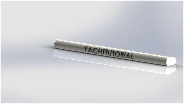
The radar of the yatch is symmetric i,e we can model only one side of the radar and mirror it. The radar is modeled using features extrude boss, extrude cut, fillets. After creating one side model the other side is mirrored while mirroring enable merge solids option so that they formed single solid body. After creating we can add text to radar if needed to get more realistic, tools >> sketch entities >> text. Using split line command the text is projected on to Radar body.
HULL:
A hull is the watertight body of a ship, boat, or flying boat. The hull may open at the top (such as a dinghy), or it may be fully or partially covered with a deck. Atop the deck may be a deckhouse and other superstructures, such as a funnel, derrick, or mast. The line where the hull meets the water surface is called the waterline.
MODELLING OF HULL:
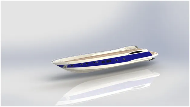
The hull is modeled using surface modeling. The hull consists of outer body, railings and port holes. In hull, the body is symmetric so we use mirror option by just designing one side and mirroring to other side with required reference plane.
The outer body is created by surface modeling. Using sketch entities the required shapes are drawn and developed into the surface modeling by features using Lofted surface, boundary surface, extrude surface, trim surface,
While the port holes are created using extrude cut and swept boss.
The railing are created by using projected curve to get the path defined, the curves are drawn on two orthogonal planes and projected to get it in required place of hull then at one end the reference plane is created and an circle is drawn. Finally the swept boss command is used projected curve as path.
The anchor is created by solid modeling features like extrude cut, extrude boss.
At the end the fillets are added at required places to get more clear views and also to remove the material.
After creating the one side, mirror it to other side and knit the surfaces properly. After knitting it the color changes to black that indicates that the feature is applied properly.
Finally the decals are added on deck surface and stairs and also appearances are changed at places for clear view.
GARAGE DOOR
Garage door is a large door on a garage that opens either manually or by an electric motor (a garage door opener).Garage doors are frequently large enough to accommodate automobiles and other vehicles.
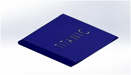
Garage door is simply modeled by just removed the unwanted portion of hull surface using extrude cut feature and saving that part separately so that we do not require any dimensions while creating it. Add fillets at sharp ends.
SEATS:
A seat is a place to sit. The term may encompass additional features, such as back, armrest, head restraint but also headquarters in a wider sense.
Three types of seats are modeled in this yatch
- front seat
- middle seat
- rear seat
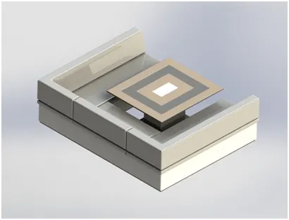
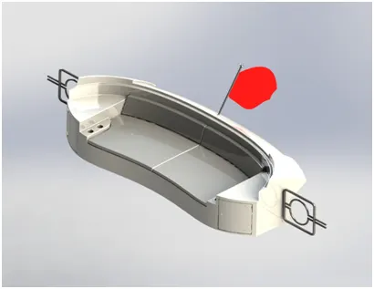
FOLLOWING FEATURES ARE USED IN MODELLING THE SEATS
- sketch entities
- surface sweep
- surface extrude
- trim surface
- surface fill
- surface loft
- knit
- chamfer
- fillet
- revolve
- knit surfaces
- extrude cut
- dome
- mirror
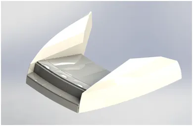
The modeling of seats includes some features of surface modeling and some of solid modeling. In these reference planes are added where ever required and fillets, chamfer to added to get more realistic view. While mirroring always enable merge solid bodies option. Finally the appearances are added for color and materials of seat to view clearly.
SUPERSTRUCTURE:
A superstructure is an extended construction of any building or platform that rises above the rest of the building or platform in a distinct manner. The size of the superstructure has a great influence on the mobility of the vessels. They are designed in a manner, so that, they add value and hinder the speed and mobility in the least. The superstructure is mostly designed in fashion as well. This is because it is the most easily visible part of the ship, in fact it is the identification of the ship, and so the designers try to provide it with the identity that is unique. The design may differ from ship to ship. Therefore in some ships we may find it to be sticking out vertically and strongly from a relatively flat deck. In many ships the superstructure is broader and bigger in size and area.
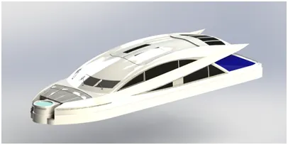
MODELING OF SUPERSTRUCTURE:
First step is to import the deck surface of hull as interface surface by insert >> part and uncheck all options and enable surface bodies. This helps in assembly of yatch so that it gets assemble directly without any required mates.
Most of the bodies are always symmetric so it is easy to model one half and mirror it with another half. Draw the required lines on the deck surface using sketch entities and using extrude surface option create the other most wall of the superstructure. Create reference planes where ever required. After creating knit the surfaces properly to check whether the knitting is performed properly see the colour of the edges changes from blue to black after the feature is used. If it is not changed then there might be small gaps between the surfaces and resolve that gaps issue and re apply the feature. Trim the unwanted surface using trim surface option
The Jacuzzi is transparent to show the water level.
Fillets , chamfer are applied to the edges of the superstructure. Appearances are also changed.
Vipers are created at the front of mirrors using features like extrude cut, extrude boss, fillets.
RADARMAST
The mast of a sailing vessel is a tall spar, or arrangement of spars, erected more or less vertically on the centre-line of a ship or boat. Its purposes include carrying sails, spars, and derricks, and giving necessary height to a navigation light, look-out position, signal yard, control position, radio aerial or signal lamp. Large ships have several masts, with the size and configuration depending on the style of ship. Nearly all sailing masts are guyed.
MODELING OF RADAR MAST
First step is to import the deck surface of hull as interface surface by insert >> part and uncheck all options and enable surface bodies. This helps in assembly of yatch so that it gets assemble directly without any required mates.
The radar mast is created using features like extrude boss,extrude cut, fillets, chamfer, swept , revolve. All features are use to create on side of the radar mast and simply mirror it as it is symmetric. There are 2 horns on radar mast which are created using shell, revolve features and add dome, fillets. While mirroring enable merge solid bodies option and create it.
At last add appearances to change color where ever required to get realistic view.
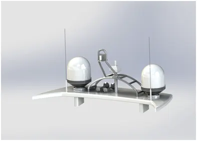
ASSEMBLY OF YATCH:
After all the components are created. Now the next step is to assemble all the parts to get Yatch.
- The first step is to insert the outer most component i,e Hull since all the parts are mounted on it and make sure you fix it.
- Next step is to insert the parts one by one by give mates so that they are in respective positions and you may fix them or make them to rotate for some particular angle.
- But here no need are giving mates since all the bodies are created on deck surface while importing directly tick on check option without giving mates so that it gets fixed to the desired location.
Features :
- Inserting parts
- Mates
RENDERING
Rendering or image synthesis is the process of generating a photorealistic or non-photorealistic image from a 2D or 3D model by means of a computer program.
Rendering in solidworks is done in 2 ways
- Photoview 360
- Solidworks visualize
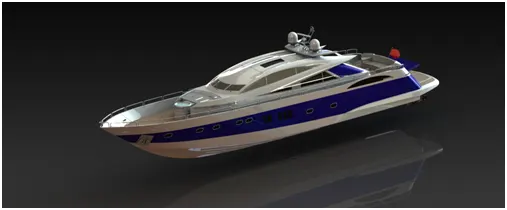
Photoview 360:
Photo View 360 enables technical users to create sophisticated, high-quality renderings of their design directly within SOLIDWORKS. It gives users the ability to demonstrate and interact with CAD models in 3D, providing perspectives and angels that would be unavailble in 2D. Users can apply appearances, background scenes, decals and more, right from the 3D CAD model. It provides a highly interactive environment for viewing designs as well as for creating photo-realistic renderings that can be used to showcase our designs.
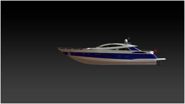
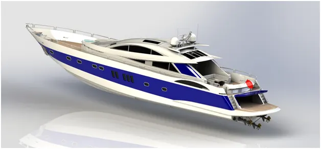
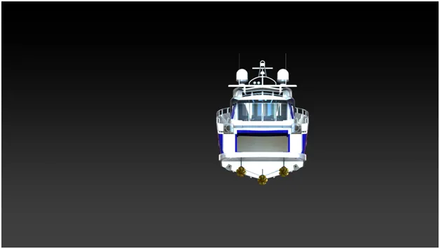
SOLIDWORKS Visualize:
SOLIDWORKS Visualize is a standalone software package designed to take 3D CAD data and transform it into photorealistic images and animations that are ready for print and web in minutes. The intuitive interface allows even non-technical users to develop rich, lifelike visual content with ease.
CONCLUSION:
The modeling of yatch is learnt in solidworks and rendering is done on all parts including assembly.