Radar Mast & Final Assembly of Yacht
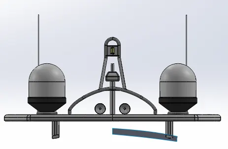
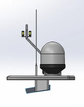
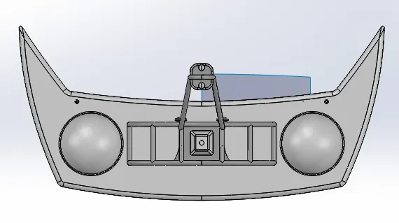
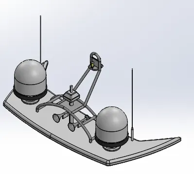
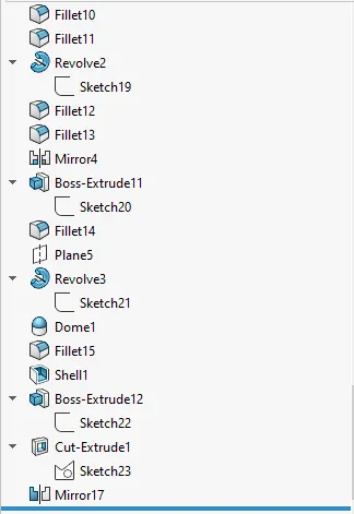
NITIN_RADAR_MAST
NITIN_ASSEMBLY
MODELLING OF SUPERYACHT IN SOLIDWORKS
INTRODUCTION
Solidworks is a widely used modelling software, provides us capability of putting our imagination into real time 3D models. Creating 2D sketches and converting them into 3D models by using features and tools inbuilt. Both Surface modelling and solid modelling is used in the project to develop a Super yacht model.
Solidworks 2018 version is used to complete this project.
OBJECTIVE
- Model the individual parts of the Super yacht.
- Assemble the parts of the super yacht.
- Appling Decals, appearances, camera, lights etc.
- Finally, rendering the super yacht to photorealistic model using photoview 360.
DESIGN METHODOLOGY
The following layout drawing will depict the approach used to create the model in the software.
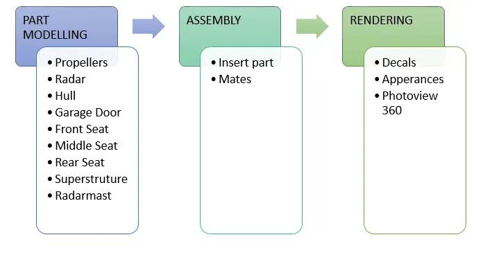
NOTE: The parts designed are explained below in tabulated form along with the features and there uses. The features used for each part are in sequence and the use is not repeated if mentioned in the table above.
PART MODELLING
- Propeller: A device used to convert the rotary motion to linear motion. Used to maneuver the Super yacht.
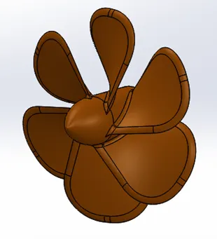
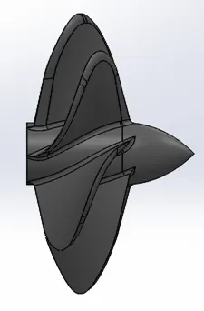
- Features used to design the propeller are tabulated below.
|
S.NO |
FEATURE USED |
USES |
|
1 |
Sketch |
2D sketch representation of model. |
|
2 |
Revolve |
Adds or remove material by revolving along an axis. |
|
3 |
Loft |
Helps creating complex geometry, by interpolating two profiles in different planes giving a path and profile. |
|
4 |
Planes |
|
|
5 |
Cut extrude |
Eliminates desired portion from the body. |
|
6 |
Circular pattern |
Patterns one or more feature along the circle both symmetrically and asymmetrically. |
|
7 |
Fillet |
Creates rounded profile along the edges. |
2. Radar: Used for communications purpose.
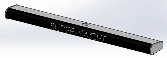
Features used to design the radar are tabulated below.
|
S.NO |
FEATURE USED |
USES |
|
1 2 3 4 5 6 7 8 |
Sketch Boss extrude Fillet Cut extrude Sketch pattern Mirror Split Line |
Using a 2D sketch creates a 3D model. Used to create ‘n’ number of identical sketch. Creates a copy of a feature or body about a face or plane. Projects the sketch on a surface of the body part. |
3.Hull: The lower portion or base of the yacht.
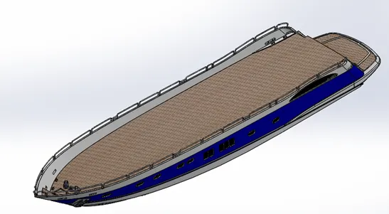
- Features used to design the hull are tabulated below.
- Surface modelling: Modelling external surfaces of a body while creating a smooth shape by making use of surface features and 3D sketches.
|
S.NO |
FEATURE USED |
USES |
|
1 2 3 4 5 6 7 8 9 10 11 12 13 14 15 16 17 18 19 20 21 22 |
Sketch Reference planes Import blueprints Projected curves Surface loft Surface trims Surface extrudes Surface knits Surface fills Shell Boss Extrude Cut Extrudes Fillet Chamfers Boss sweep Revolve Dome Helix spiral Linear pattern Split lines Offset surfaces Mirror |
Create sketches in planes other than standard planes.
Used for references while creating the hull.
Creates 3D curves onto the surface by creating two different sketches in two different planes. Generates complex geometry by interpolating surfaces between various cross-sections. Using a surface, plane or sketch as trim tools can trim intersection surfaces. Used for extruding surfaces from the boundary edges.
Combines two or more surfaces into one. Used to fill gap in a model. Creates a hollow body of varying wall thickness.
Creates a bevel feature on the edges. Sweep a closed profile along a closed or open path to make solid body. Makes curved formation or structure. Creates helix or spiral for lofting or sweep.
Creates a new surface body at a distance from the face. |
4.Garage door: Hinged door for the garage.
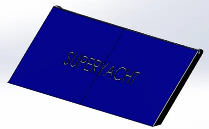
- Features used to design the garage door are tabulated below.
|
S.NO |
FEATURE USED |
USES |
|
1 2 3 4 5 |
Sketch Cut extrude Shell Fillets Mirror |
5.FRONT SEAT: Seat for the front portion of the yacht.
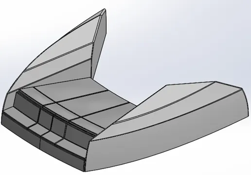
- First importing surface body of the hull for the base of the seat.
- Features used to design the front seat are tabulated below.
|
S.NO |
FEATURE USED |
USES |
|
1 2 3 4 5 6 7 8 9 10 11 12 13 14 15 |
Reference plane Sketch Surface sweep Surface extrude Surface trim Surface fill Surface loft Surface knit Chamfer Revolve Cut extrude Cut extrude thin Fillet Mirror Dome |
Uses a sketch or curve or edge as a path, can be open or closed and creates a surface along it of sketch2.
|
6.MIDDLE SEAT: Seating arrangement on the yacht.
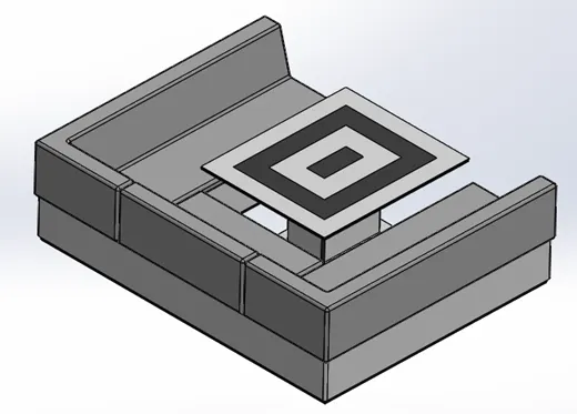
- Features used to design the middle seat are tabulated below.
|
S.NO |
FEATURE USED |
USES |
|
1 2 3 4 5 6 7 8 |
Importing surface bodies Sketch Boss extrude Reference planes Chamfers Fillets Mirror Cut extrude |
|
7.Rear seat: Seating place at the end of the yacht.
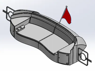
- Features used to design the rear seat are tabulated below.
|
S.NO |
FEATURE USED |
USES |
|
1 2 3 4 5 6 7 8 9 10 11 12 13 14 15 16 17 18 19 20 |
Importing surface bodies Sketch 3D sketch Surface sweep Surface offset Surface trim Ruled surface Surface knit Surface trim Reference planes Surface extend Surface loft Surface fill Boss extrude Cut extrude Chamfer Fillet Sweep Mirror Revolve |
3D sketch can be made anywhere in the 3D space.
Offsetting a distance from the surface.
Ruled surface is a tangent extension in a particular direction to complex surfaces |
8.Superstructure: The top portion of the super yacht where the captain operates the yacht.
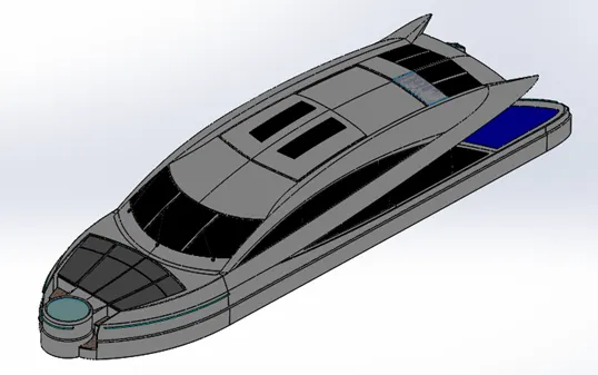
- Features used to design the superstructure are tabulated below.
|
S.NO |
FEATURE USED |
USES |
|
1 2 3 4 5 6 7 8 9 10 11 12 13 14 15 16 17 18 19 20 21 22 |
Import surface bodies Sketch 3D sketch Surface extrude Planes Surface sweep Surface knit Fillet Ruled surface Surface trim Projected curve Surface loft Surface fill Surface trim Surface extend Boss extrude Cut extrude Dome Sweep Extrude thin Chamfer Mirror |
|
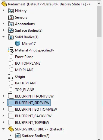
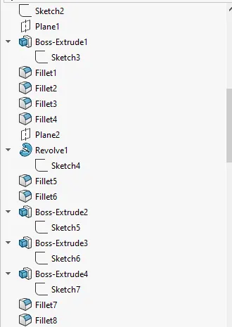
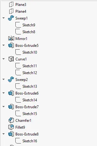
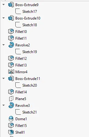
9.Radar mast: Used for communication purpose.
- Features used to design the superstructure are tabulated below.
|
S.NO |
FEATURE USED |
USES |
|
1 2 3 4 5 6 7 8 9 10 11 12 |
Import surface bodies Sketch Plane Boss extrude Fillet Revolve Sweep Mirror Projected curve Chamfer Dome Shell |
|
ASSEMBLY
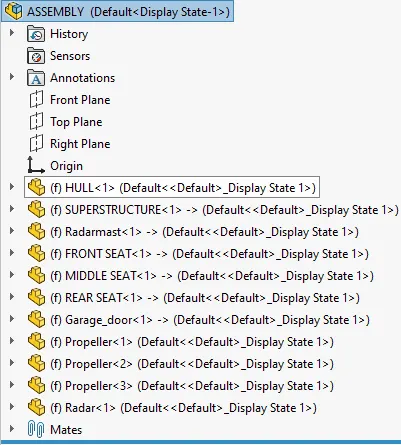
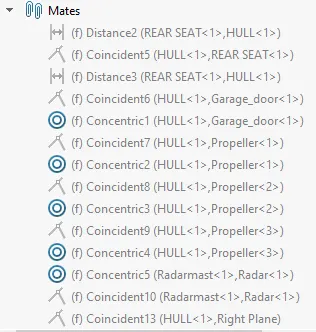
There are in total 9 components of the super yacht built separately, in order to look like a super yacht these components should be assembled using different types of mate relations and inserting the components one by one.
Main steps:
- Insert parts
- Mates (apply appropriate relations like coincident, concentric offset etc.)
MATED APPLIED
We have imported the base of the hull for many other components, as we import those components they get to their respective places one by one directly.
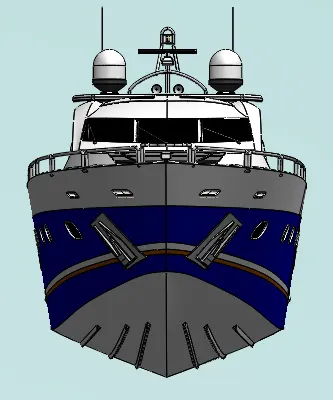
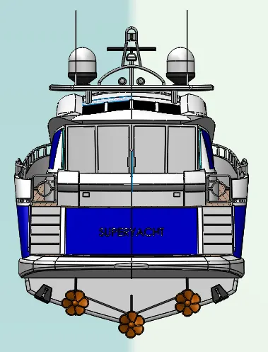
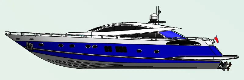
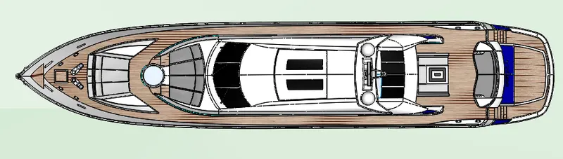
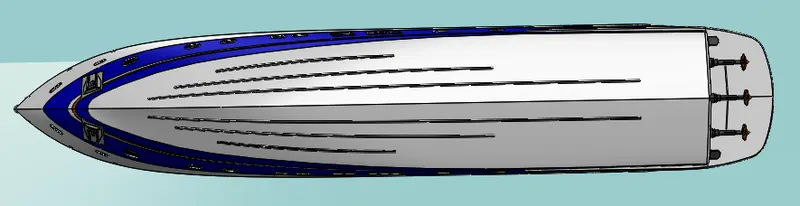
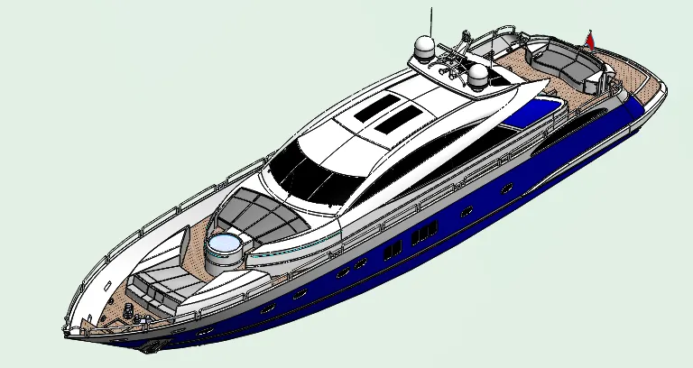
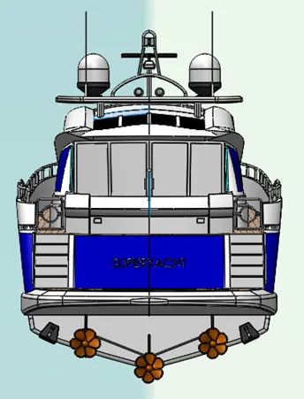
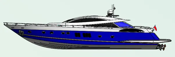
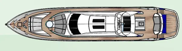
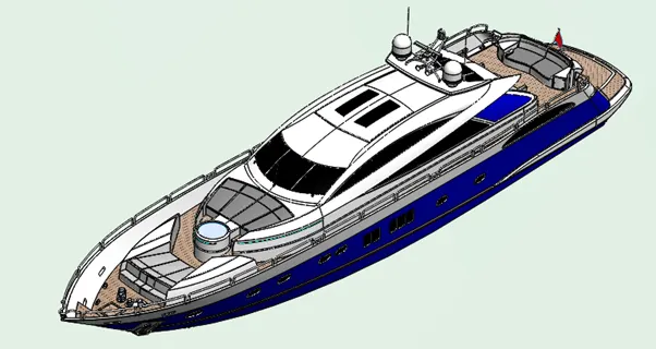
Assembled views of SUPER YATCH
- Front view
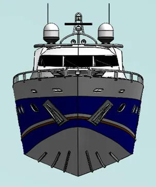
- Back view
- Side view
- Top view
- ISO
RENDERING
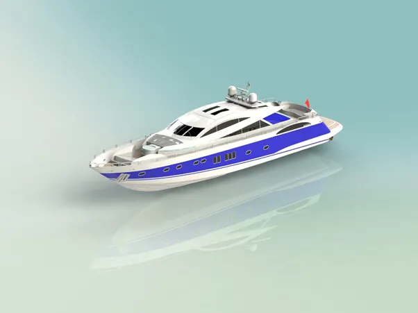
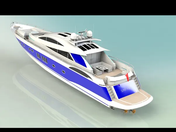
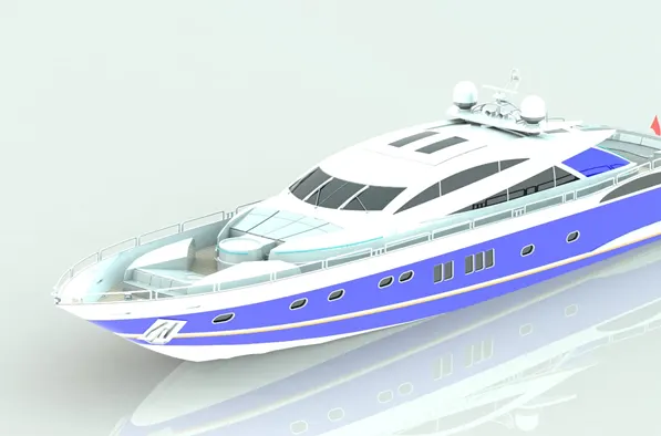
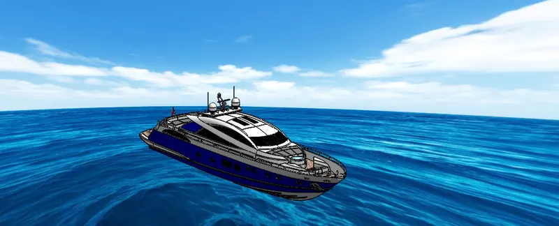
Rendering allows to give a photo-realistic perspective to the model created by Photoview 360.
Photoview 360 is a rendering tool inside the Solidworks to create photo-realistic model.
The following are some rendered photos created by photoview 360
- Isometric render view
- Camera setup view
CONCLUSION
- Creating parts of the super yacht using surface and solid modelling.
- Inserting and mating the parts to assemble the model.
- Finally rendering the model to give the model a realistic image using Photoview 360.